5. Electronics production
This week is about milling a circuit board and soldering components on the board
The group assignment
This week the team worked on the analysis of the differance between milling with a 1 flute bit and a 2 flute bit and the differance between climb milling an conventional milling. In the end we had four results:
1 flute climb
1 flute conventional
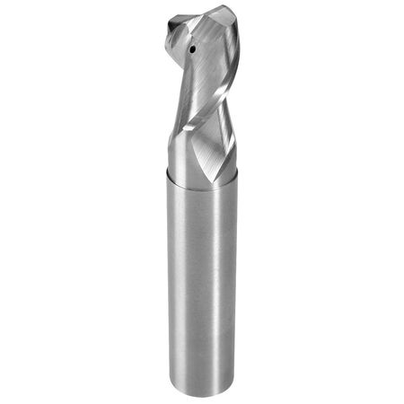
2 flute climb
2 flute conventional
The best result was 1 flute climbe (see goup assignment
The individual assignment
I worked on milling and soldering the in-circuit programmer FabTinyISP Brian
The Milling machine
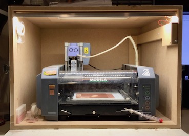
For producing PC boards we use the Roland Modela MDX 20 Milling machine because it can do very precise milling.
For the boads we use FR 1 board, it’s a thin copper layer on a basis made out of pressed paper.
There is also FR 4, but that has a glass fiber basis wich is hazzardous when being milled. So we don’t use that.
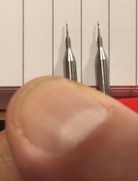
For milling end bits we use
• 0.4 mm for the traces, the tracers are the conductive copper parts on the board
• 0.8 mm for cutting out the board
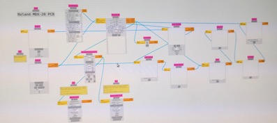
The software we use is Mods (Community Version). Mods stands for Modules: from the file you want to mill a series of Modules convert the file so that the machine can handle is. In each Module you can adjiust the proces.
Start the milling software
On the desktop you see the short cut for the program
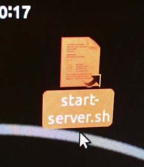
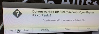
Click on start-server.sh on desktop
A Pop up appears:
Do you want to run “start-server.sh” or display its contents?
Click on Run in Terminal
This opens Firefox and the Terminal
Right mouse click
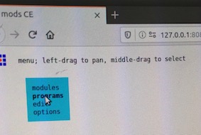
A blue window appears:
Click on “programs”
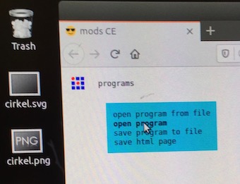
A new blue windor appears:
Click on “open program”
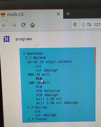
A list of machines appears:
Go to the MDX-20 Mill and click on “PCB”
MODS opens
Got to Step 1: Load either a PNG or SVG image
In this case click on Select PNG file in the lower MOD, because my file is a .png
Click Select png file. This opened my USB stick. I selected fts_mini_traces.png.
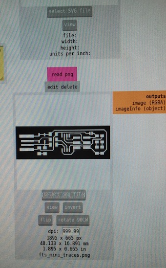
PNG file will show in window
1 Go to Set PCB defaults
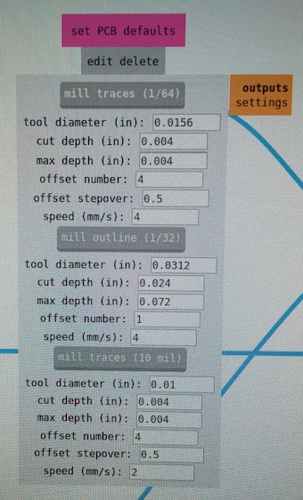
For milling traces click on “mill traces (1/64)”
It shows
• the diameter of the bit 0.0156 inch
• cut depth wich is how much of the copper foil wil be removed
• the offset number is 4 witch means the the mill will make 4 passes to do the tracing
• the offset stepover is 0.5, this indicates the overlap between two passes
• speed is set at 4 mm/s, this is to fast for the bit, but I will change the speed in another Mod.
I did not change the settings
2 Go to Mill Raster 2D
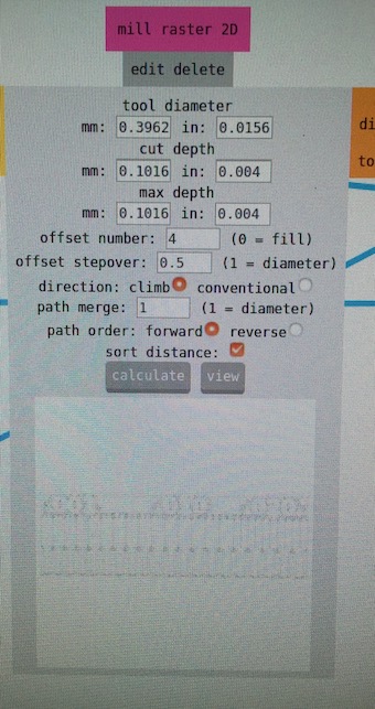
In this window you see the diameter of the bit, the cut depth eand maximum depth. Also the offset numer and stepover. I left these settings as they are.
• Offset number should be 4 for tracing
• Offset stepover should be 0.5 for tracing
• Choose climb for directions, this gives a better result
• Leave path merge on 1
• Set path order to forward
• Click on calculate. In the lower window you see the tracing result.
• Click on view and you see the schematic path the mill will follow. Notice the 4 lines of the offset.
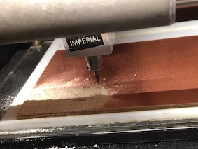
Preparing the mill
First I had to prepare the bed to put the copper plate on
The bed of the mill is build up in three layers.
• the ground bed
• the acrylic bed, this keeps your work leveled
• the sacrificial bed, to avoid damage to the acrylic bed
 Remove the bed from the mill by unscrewing the 2 screws at the front
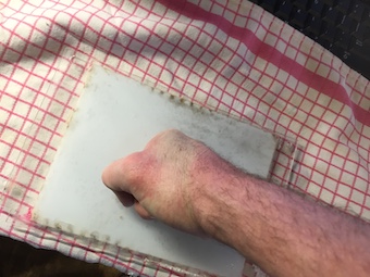
• remove board from the previous job. (This should be done because FabLab rule is “Leaf the place better than you found it”. I’ll discibe it anyway) Use a putty knife
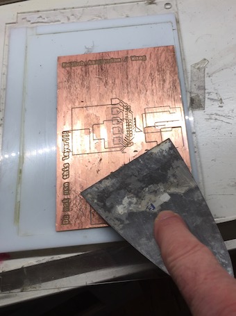
• then remove rests of dubbel sided tape from the previous job. First with the putty knife.
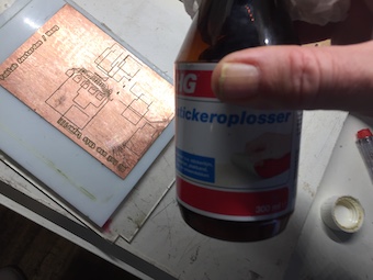
• Then clean with sticker remover. Use paper towel
Check if the bed is clean of paper and that it is flat
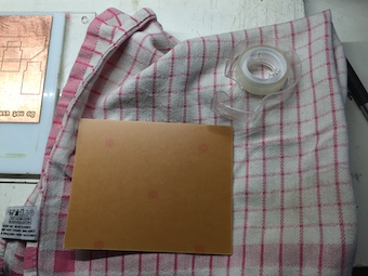
• Take a new copper board.
• Lay it up side downon a soft cloth to avoid scratches on the copper.
• Stick double sides tape over the total width. I used 7 strips. This avoids your work from moving during the milling process. Make sure it is flat, and there are no air bubbles under the tape.
• Put the new board on the sacrificial layer on the bed
• Press very hard to fix the board to the bed.
• Slide the bed under the two bolts at the back.
• Then screw the two screws at the front of te bed.
• Pres View mode, bed is moving to the front. You can do a last check.
• Press View mode again. The bed is moving backwards
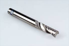
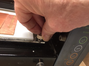
Check what bit is in the machine. I had to change the bit. I use a 1 flute .40 mm bit. That came out as the best from our group assignment.
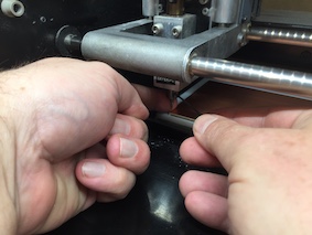
 Take the bit between index and middle finger while your hand is upside down, while unscrewing the allen bolt. This is the prevent the bit from being damaged by falling. Even from this short distance.
Put the new bit in, as deep as possible. You will ajust this later. Fasten the allen bolt.
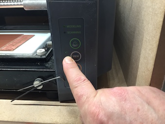
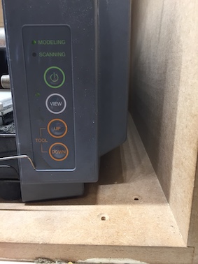 • Lower de Z Ax all the way down by pressing Down.
• When the Z Ax is down move it up just a little bit by pressing Up. This space should give the machine enough space to do the tracing.
• Lower de Z Ax all the way down by pressing Down.
• When the Z Ax is down move it up just a little bit by pressing Up. This space should give the machine enough space to do the tracing.
Back to the software
3 Go to the window Roland MDX-20 milling machine
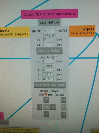
• For tracing set speed at 1 mm/s not faster otherwise the bit will break (For cutting set speed at 4 mm/s The thicker bit can handle this speed)
• Set origin with X and Y
• Click on Calculate in the Mill Raster 2D window.
• Click on Move to origin
Check is the mill send the bit to the right posision. If not adjust X and Y click on Calculate and click on Move to origin. Repeat till the bit is in the right position.
Back to the Milling machine
The bit is now above the origin point.
• Unscrew the allen bolt that keeps the bit in place. Support the bit with one finger to prevent it from falling on the copper plate. It would brake. • Lower the bit carefully til it is on the copper plate. • Fasten the allen bolt. • Machine is now ready to mill.
Back to the software
4 Go to Websocket
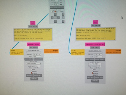
There are two websocket windows: websocket serial and websocket python serial. I used the websocket python serial
Websocket Python serial Adress is 127.0.0.1 Port 1239
• Click “open socket”
Serial port: /dev/ttyUSB0 Baud rate should be 9600 Flow control choose RTSCTS
• Click “open port”
• Click “send file”
The mill starts to mill
After a while the tracing is done. Time to cut the outline
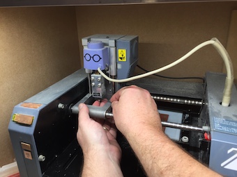
5 Change the bit
Follow the procedure as discribed above
• Unscrew the .40 mm bit while holding it between two fingers.
• Put it directly back in the box to prevent damage or loss.
• Mount the .80 mm bit while holding it between two fingers.
• Mount it as high as possible
• Lower de Z Ax all the way down by pressing Down. • When the Z Ax is down move it up just a little bit by pressing Up. Do it a little less then with the tracing. This space should give the machine enough space to do the cutting.
• Move to the origin point • Lower the bit to the copper plate. Follow the procedure as discribed above.
Select the file fts_mini_cut.png. It shows in the window
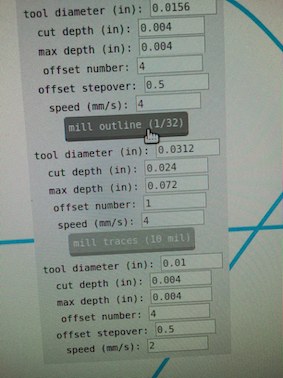
6 Go to pcb defaults
• click on Mill outline (1/32)
It shows the dameter of the bit
the cut depth and maximum depth
the offset number
teh speed
Notice there is no offset stepover since the mill will follow only one line. Notice the the speed is 4 mm/s wich is possible because of the thicker bit.
7 Go to mill raster 2d
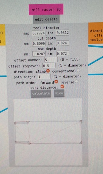
I chose 5 for offset number. I think this could be lower, but it worked
I left all the other values in tact
• click on calculate
• click on view
Although it is not the view window, you ca see the paths in the small window at the bottom.
8 Go to Roland MDX-20 milling machine
• Set speed to 4 mm/s
• Leave origin as its is so the milling will start at the right point. On the photo the y = 9 mm witch is strange becaus it should be 8 mm.
• Click on move to origin.
9 Go to Websocket Python Serial (see above)
• click on open socket
• click on open port
• click op send file
10 Don’t forget to lower the bit! On the photo it says “cancel” instead of “send file”. I had to cancel the first run, because I forgot to lower the bit. After canceling I had to reset the mill by pressing View and then pressing Up and Down at the same type. The lower led starts to blink. When it finished blinking the mill is reset. I had to do it several times to get the mill realy resetted.
Cutting in proces
11 My first board
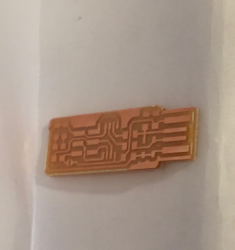
Looks good. I scraped away the tiny bit of copper in front of the YUSB connections as instructed in the documentation. The picture is from the documentation.

Time to solder
12 Soldering
For the soldering I used the documentation Building the FabTinyISP witch can be found here
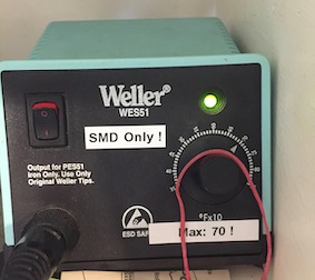
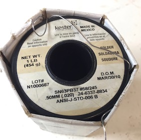
For the soldering I used this soldering station and this solder
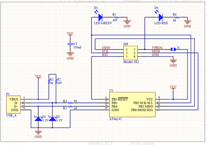
First I looked at the schematics in the documentation. 3 things from the documentation came in verry handy
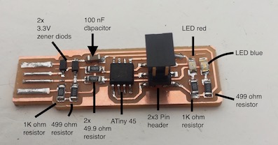
1 The list of the components
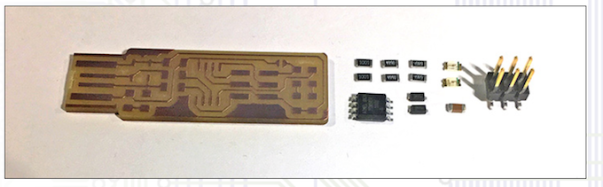
1x ATtiny45 2x 1kΩ resistors 2x 499Ω resistors 2x 49Ω resistors 2x 3.3v zener diodes 1x red LED 1x green LED 1x 100nF capacitor 1x 2x3 pin header (list is from the documentation)
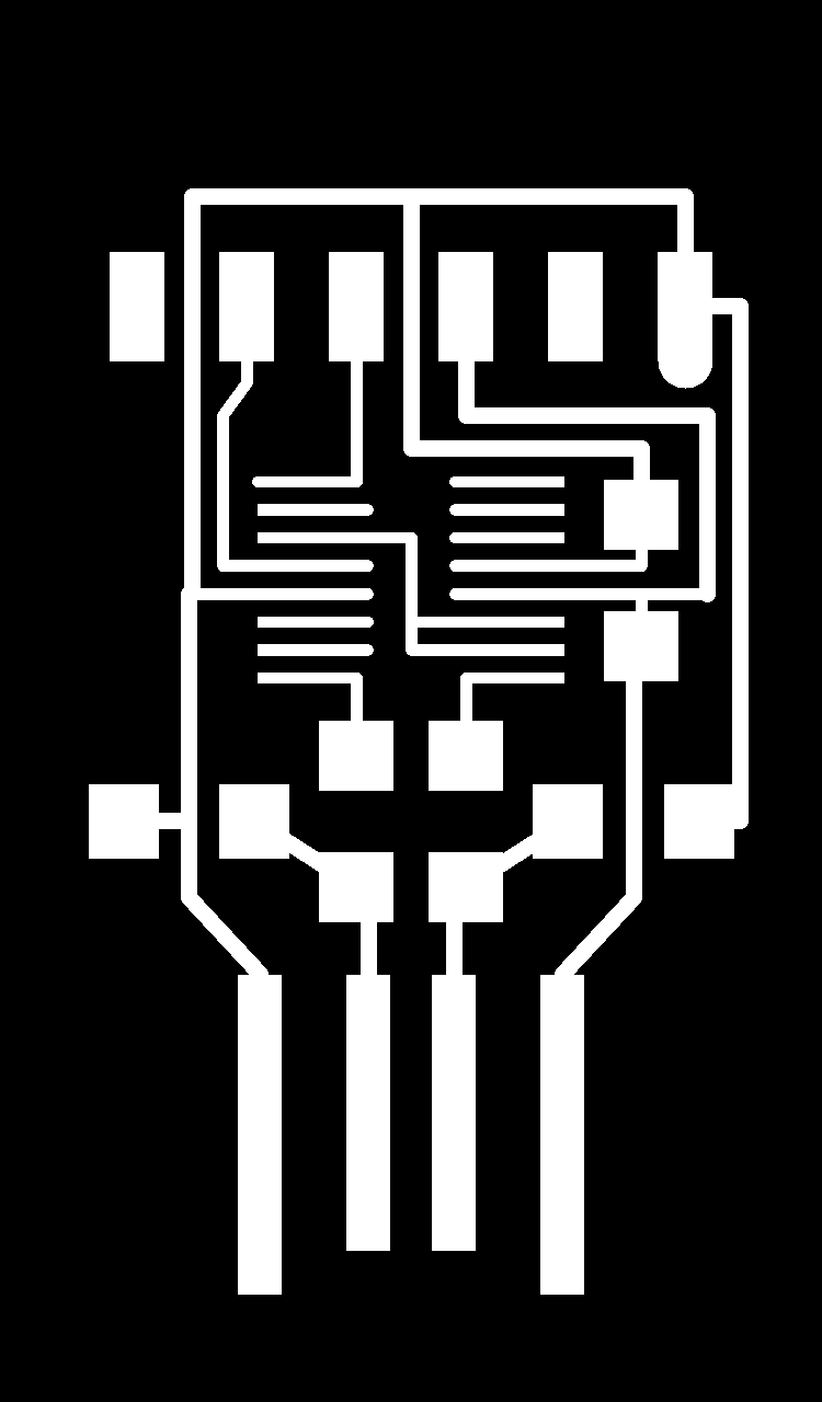
2 The board image
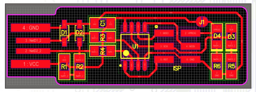
3 The board schematic
Getting all the parts was not a big problem because of the labeling on al of the drawers.

For the soldering I used the tips we got from Neil and our instructor
• Solder from the inside out so parts that you already soldered won’t be in the way.
• Save large parts (for instance the 2x3 pin header) for last, they might get in the way.
• Solder in four steps:
1 heat the connection with the iron
2 melt a tiny drop of solder on the connetion
3 take the solder away
4 take the soldering iron away
• First put some solder on one of the connections you want to solder a componant on.
• Then wit a pair of tweezers hold the component in place and heat the connection till the solder flows nicely between the connection and the board
• Then solder the other connection
This is the result
12 Checking the board
I checked the board visualy and found a loose connection on one of the LED’s. I fixed it.
I tried to check my board by setting a multimeter in 200 Ohm and connecting several contacts. Sometimes the mutimeter gave a signal, sometimes not. Even with the help of the scheme I couldn’t figure what to do.
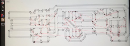
With the help of my neighbour I made a coloured scheme of the board. Now I had a scheme to check the VCC circuit, the Ground circuit and the data circuits
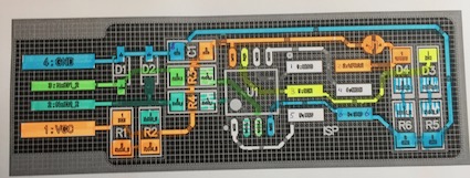
With a multimeter I checked all the connections for each colourd line.
The board is okay.
Programming the board
1 I downloaded Crosspack
2 I downloaded the firmware source code
3 I opened Terminal, changed directory to the Firmware folder and ran “make” The file fts_firmware.hex was created
4 I did not have to edit the line PROGRAMMER ?= usbtiny since the the programmer we use is a usbtiny.
5 I hooked the programmer, my board to my Macbook with a USB 2 Hub. Both red LED’s are burning.
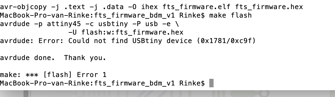
6 I typed avrdude -c usbtiny -p t45 I had to do that before typing make flash
But I got this massege:
Error MacBook-Pro-van-Rinke:fts_firmware_bdm_v1 Rinke$ avrdude -c usbtiny -p t45 avrdude: Error: Could not find USBtiny device (0x1781/0xc9f)
avrdude done. Thank you.
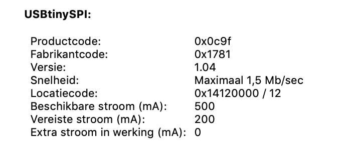
• The problem was not in the USB connection. I hooked it up with 2 different USB 2 connectors and my system could see the tiny
• The problem was not in the board, because Henk tested the board on his computer and the hardware was okay. • We tested it on Hyejin’s computer and is was okay.
So the problem had to be in my Macbook
It seems I have to install XCode in order to use commandline properly. Downloading took to long so I could borrow Hyejins computer (and her help)
We typed the following commands. It is not all clear to me what happens. I copy pasted from Brians manual.
Type “make flash” This will erase the target chip, and program its flash memory with the contents of the .hex file you built before. You should see several progress bars while avrdude erases, programs, and verifies the chip
Type “make fuses” This programmes the board. This will set up all of the fuses except the one that disables the reset pin. Again, you should see several progress bars from avrdude. What I understands from this is that the result is that you get a USB device that can program but can not be progammed.
Type “make rstdisbl” This does the same thing as the make fuses command, but this time it’s going to include that reset disable bit as well. You should see some progress bars, and with that, avrdude will never be able to talk to this chip again through the ISP header. So the board is now completely inaccesseble.
Milling and soldering the FTDI Board
In the near future we need another board then the Tiny: the FTDI board. So I made that one this week.
The milling went the same as the Tiny
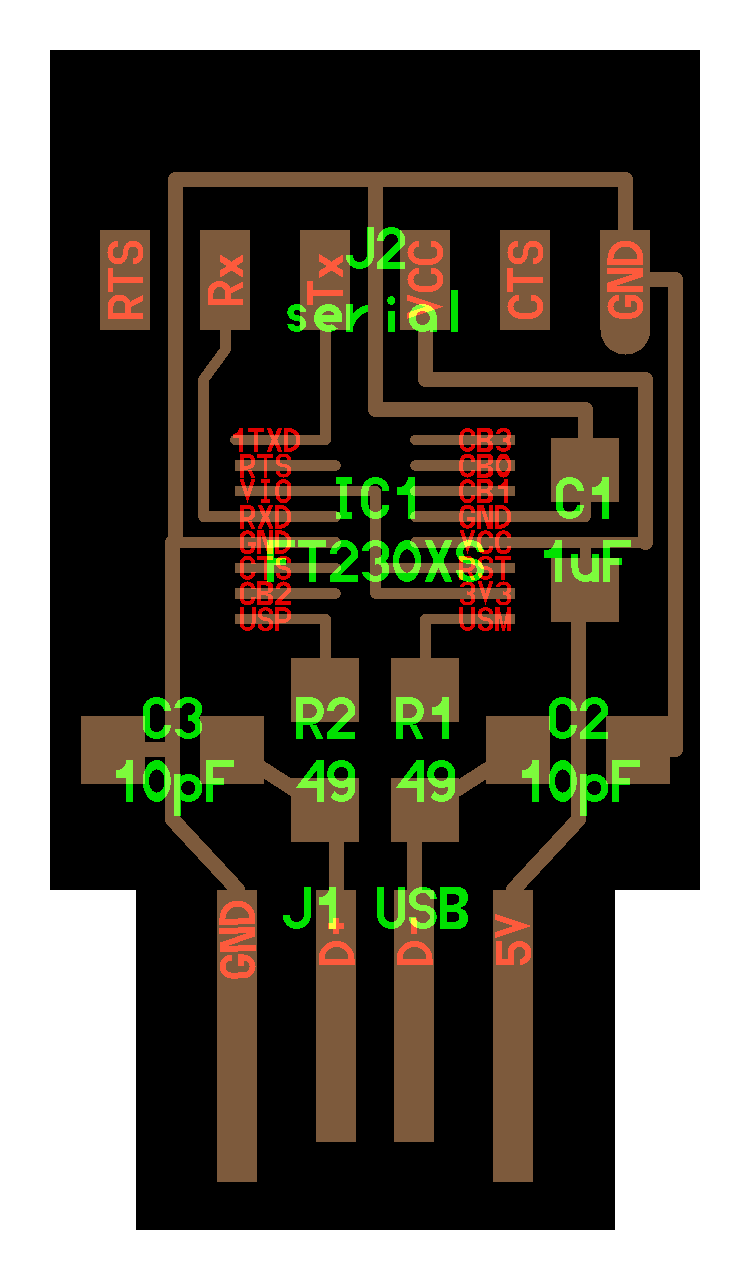
For soldering I uesed the schematic above and this image

The soldering technique was slightly different. The 2x 8 legs of the chip are very close to each other. Soldering them one by one is not possible so I soldered them as one.
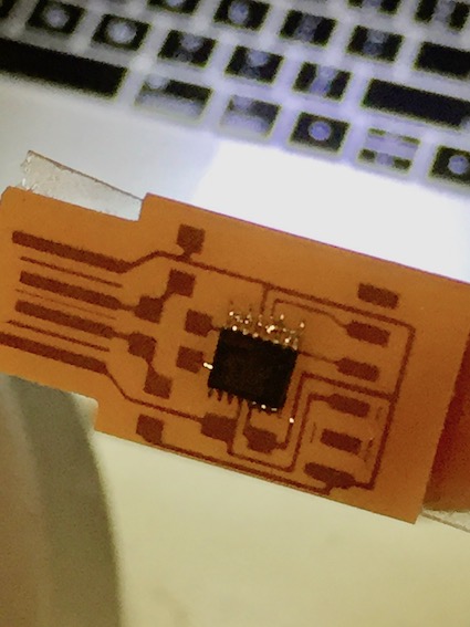 After taht I took a desoldering iron to suc away the surplus of solder. Now non of the legs is connected to another.
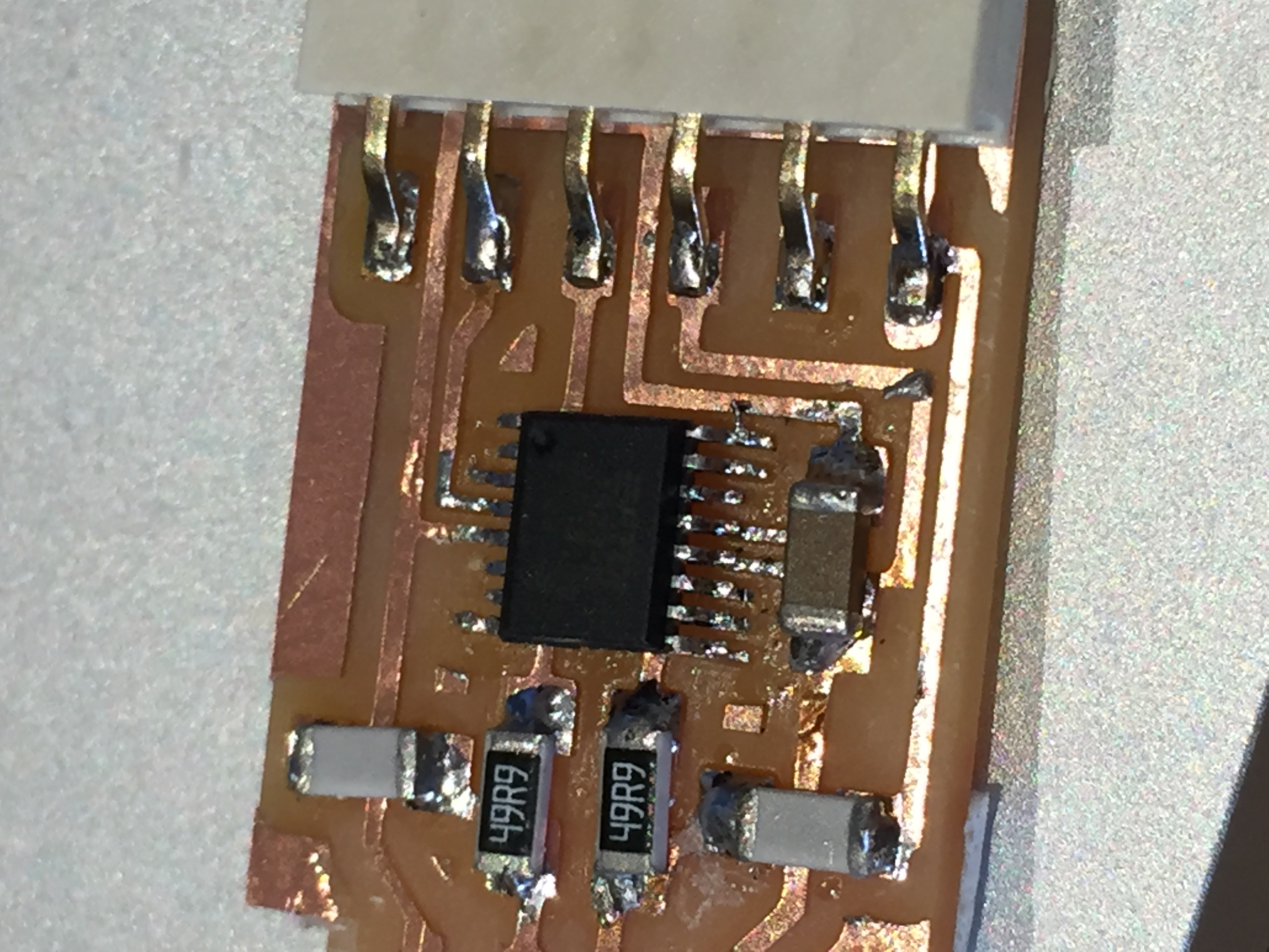
The result looks nice
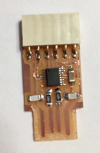
The FTDI is visible on USB 2 hub on my Macbook
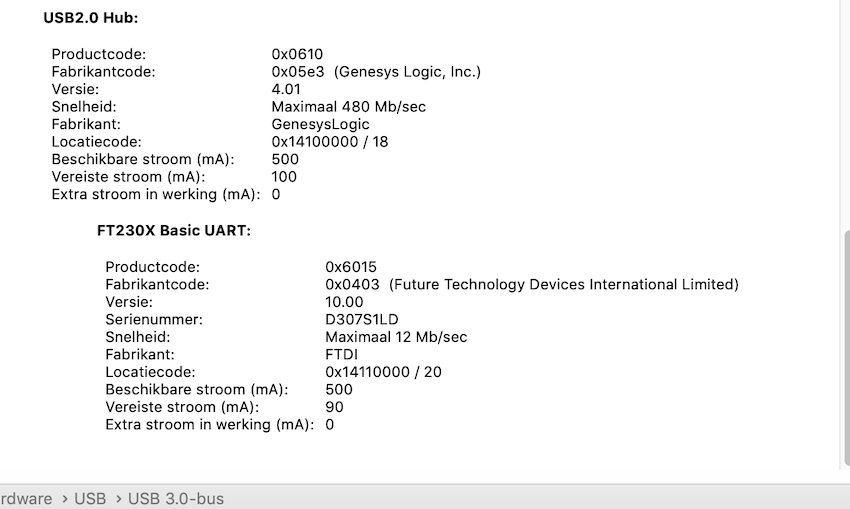
Then I had to install the driver for the FTDI. I found them on FTDIChips.com > VCP Drivers > Mac OS9 and up > FTDIUSBSerialdriver
The installation was succesful.
List of things I should remember
AVR AVR is a family of microcontrollers developed since 1996 by Atmel, acquired by Microchip Technology in 2016. These are modified Harvard architecture 8-bit RISC single-chip microcontrollers.
AVRDUDE AVRDUDE is a utility to download/upload/manipulate the ROM and EEPROM contents of AVR microcontrollers using the in-system programming technique (ISP).
Microcontroller A microcontroller (abbreviated MCU or µC) is a computer system on a chip that does a job. It contains an integrated processor, memory (a small amount of RAM, program memory, or both), and programmable input/output peripherals, which are used to interact with things connected to the chip.
FTDI Future Technology Devices International
ISP ICP In-system programming (ISP), also called in-circuit serial programming (ICSP), is the ability of some programmable logic devices, microcontrollers, and other embedded devices to be programmed while installed in a complete system, rather than requiring the chip to be programmed prior to installing it into the system.
ISP ICP In-system programmer, does the above
.HEX FILE Intel HEX is a file format that conveys binary information in ASCII text form. It is commonly used for programming microcontrollers, EPROMs, and other types of programmable logic devices.
Fuses 3 bytes of permanent (by permanent I mean that they stick around after power goes out, but that you can change them as many times as you’d like) storage called the fuses. The fuses determine how the chip will act, whether it has a bootloader, what speed and voltage it likes to run at, etc. Note that despite being called ‘fuses’ they are re-settable and dont have anything to do with protection from overpowering (like the fuses in a home).
Make flash Command that will erase the target chip, and program its flash memory with the contents of the .hex file you built before.
Make fuses This will set up all of the fuses except the one that disables the reset pin.
Make rstdisbl This does the same thing as the make fuses command, but this time it’s going to include that reset disable bit as well. Once the RSTDISBL fuse is set, no more SPI flashing is possible.
UPDI The Unified Program and Debug Interface (UPDI) is an Atmel proprietary interface for external programming and on-chip debugging of a device.