3. Computer Aided design
This week I worked on defining my final project idea and started to getting used to the documentation process.
2D and 3D design tools Lecture from Neil 5 February
Assignment
The assignment for this week is to design something in 2D and in 3D.
Important difference between
Bitmap (Raster): pixels
Vector: lines
2D Tools
Raster
GIMP Bitmap tool for all platforms
MyPaint For freehand painting
Image Magick For adjusting pictures
Look for command line resize command
Look for command line jpg to png
Vector
Inkscape
Illustrator
3D Tools
First design in 2D, then extrude to 3D
Important functions
Sweep: makes a 3D form from a line and a form. i.e. line + circle + sweep makes tube
Constraints
Parametric design design + spread sheet >
Look at the links in the week 2 schedule
Fusion 360
Formats
STL for 3d Printer
Videos must be max 1MB Use FFMPEG
HTML 5 for MP4, FFMPEG encoding
The Fusion 360 Workshop
Timeline
Time Line (under left) keeps track of the commands
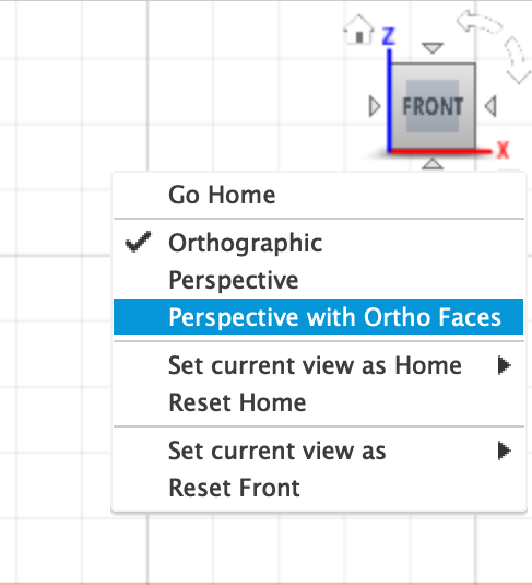
Navigation button
The navigation button helps to choose axes and change perspective
Ending funtion ar command
ESC ends used function
Click or Enter finishes a command
Browser
Keeps track of objects
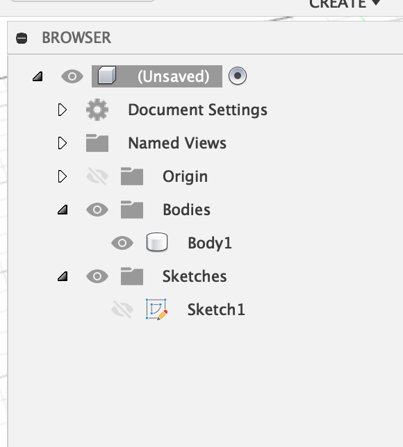
Keep bodies and sketches folders open at all time With the eye-icon you can make bodies and sketches visible and invisible
Create or open nieuw project
In the top left corner of the screen you find the project menu. Here you can create a new project or open an existing one.

Create a sketch
Chose Create a Sketch from the CREATE menu.
Then select a plane
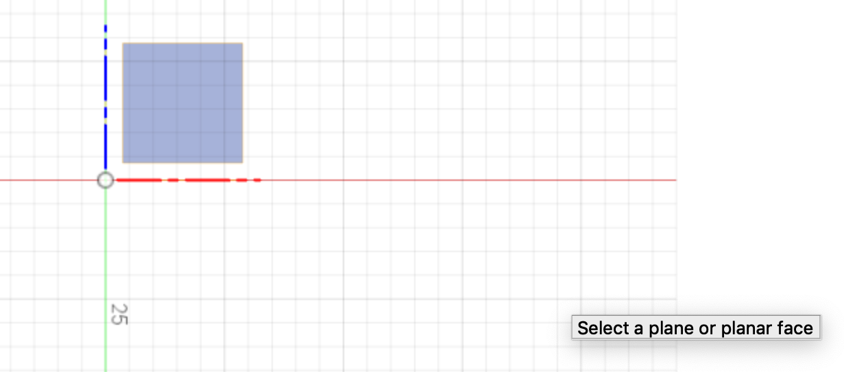
Create a rectangular (2 point) (or choose another form from the menu)
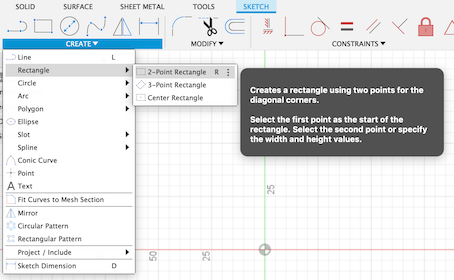
Then Finish sketch.

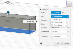
Extrude
Choose Extrude from the CREATE Menu or hit the E key. Now extrude the figure up or down dragging the blue arrow.
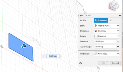
There are more ways to extrude. Choose from the extrude menu.
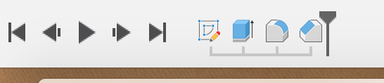
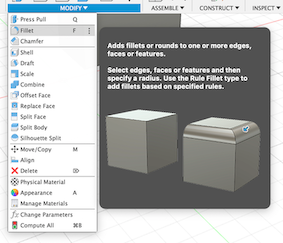
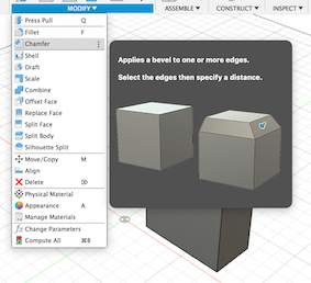
Fillet
Whith the Fillet command you create round edges on your object
Chamfer
Chamfer from the CREATE Menu gives an object shap edges.
Save
Hit Apple-S (CMD-s) to save. Notice that the Version numbre changes.

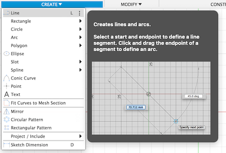
Using the Value windows
After creating a line or form just let go of the mouse button and do not click or hit enter. Next to your object you see value windows for meassurements. Use the for precise values.
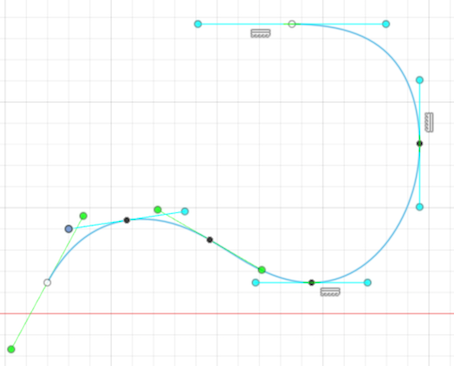
Spline
With Spline you can draw curves. Create a line with 2 or more dots by clicking with Spline. Everu dot will have to handles. You can use hem to change the curves.
Mirror
With Mirror you can copy and mirror an object. Select the object and a line to mirror with.
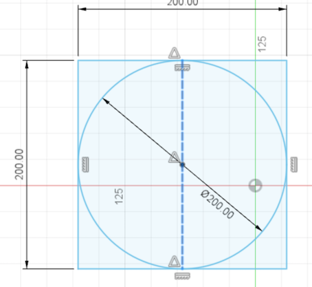
Centre
You can centre 2 object using a construction line (a line that not a part of the object) and the contraint MidPoint. The triangles guide you to centre.
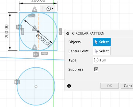
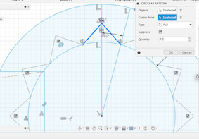
Circular pattern
You can reapeat a line or shape in a circular patern.
Revolve
You can make a 3D object by revolving a line around a given ax.
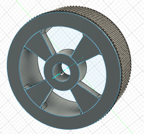
The Wheel
To practice the above I decided to do a not to difficult project. I wanted to make a wheel, because that could be usefull for my final project: a car.
I found a tutorial https://www.youtube.com/watch?v=uQTNBC_ldhs, and although it was a pretty good one, I had to start over a couple of times.
What went wrong?
I had a problem with applying the right angle of the spokes. I got confused with the inner angle and outer angle and the value window.
I removed the spoke-lines and started over. I zoomed in more so I could see what I was doing.
Some lines were to short and not centered. In stead of trying to make them the right length and put them in de right place I started over. Good exercise.
What went well?
Revolve around axis. A very logical operation Working with an off set plane. Although I had to CMD Z a couple of times.
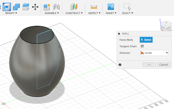
3D Assignment
I wanted to draw a car, but after the workshop I thought I had to design a Porche. Fortunitly I found out that a much more simpler concept af a car would do. Like this:
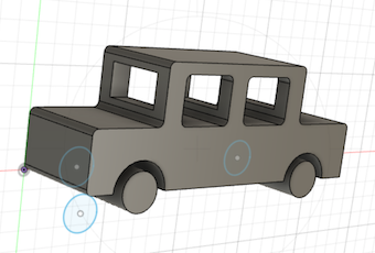
Hoe did I get there?
With the line tool I drew tie outline of the car.
With the rectangular tool I drew the two windows.
With the circular tool I drew the two wheels.
With fillet I rouded the edges.
With Extrude I extruded the sketch to a 3D model.
I wanted a front and rear window exactly centred. I drew a construction line in the middle with the help of Midpoint.
From the Create menu I took the Centre Rectangle and drew the front window from the centre.
After Finish Sketch I could do the extrusion. At first I picked the wrong point to extrude from and almost all of the top of the car was gone.
I realised I had to carefully pick the front window rectangle to extrude from. So I did, and now the car has front and rear window
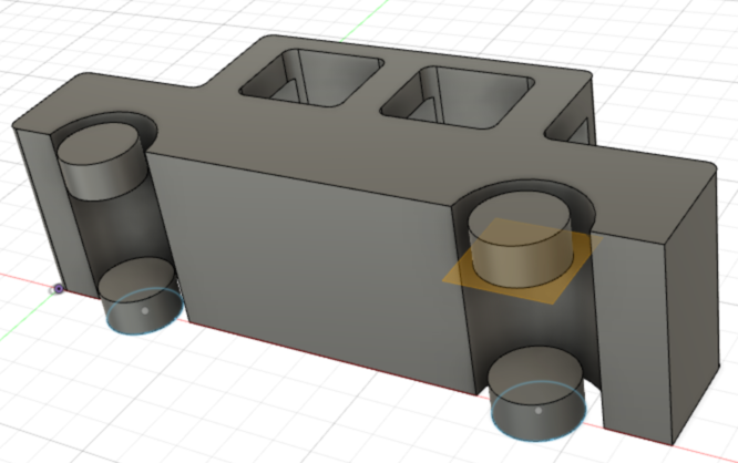
Using construction planes. I changed the “flintstone-car” wheel into 4 wheels. First I created two offset planes 10 mm from the left and right side of the car. Then I drew a circle wider then the cylinder and extruded the cylinder from one plane to the other.
Remember to make the cicle wide enough, otherwise the cylinder won’t be extruded completely. Remember to click on the right plane to extrude from.
2D Assignment
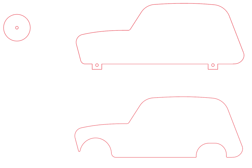
For the 2D assignment I used Adobe Illustrater. I made a drawing from technical drawing of a Renault 4.
Other programmes
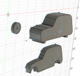
I wanted to open the Renault.ai file in Fusion
I exported the file as .dxf
I opened it i Fusion 360
I could do an extrusion.
I wanted to open teh Renault.ai file in Blendle I exported the file as .svg The file didn’t open in Blendle
I had some trouble installing Inkscape, but after installing XQuartz it ran smoothly. I did a qiuick look around in Inkscape. It opens .ai and .svg files. Looks prety straight forward.
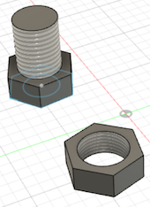
Nut and Bolt
I wanted to make a nut and bolt.
• Create hexagon
• Create circle
• Centre them with Move point to point
• Finish sketch
• Extrude the hexagon
• Extrude the circle from object.
This is where it went wrong: there was a hole in the hexagon.
What I should have done is:
• Create hexagon
• Extrude hexagon
• Finish sketch
• Creatre skecth
• Draw circle
• Centre them with Move point to point
• Extrude circle
• Create thread
Now you have a bolt
Unfortunatly I lost the .f3d file