♙ THE FOUNTAIN OF DESPAIR ♙
• • •
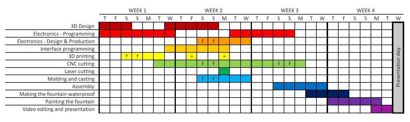
Project Development
As one might have seen by looking at the assignments of WEEK 1, WEEK 3, and WEEK 14, I originally planned to work on the design and development of a smart thigh compression sleeve. Nevertheless, around WEEK 19, I had a talk with my advisors because I was fearing not to be able to complete my final project in time. Together, we estimated the amount of work at around three months more at least because of software development and design optimisation that were supposed to be done before manufacturing. As a matter of fact, the device would have been completely useless without taking these development steps very seriously, in particular the algorithms that allow to knowingly and automatically spread the sensors inside the soft silicon smart thigh compression sleeve in such a way that the latter should give relevant data to measure what was meant to be measured.
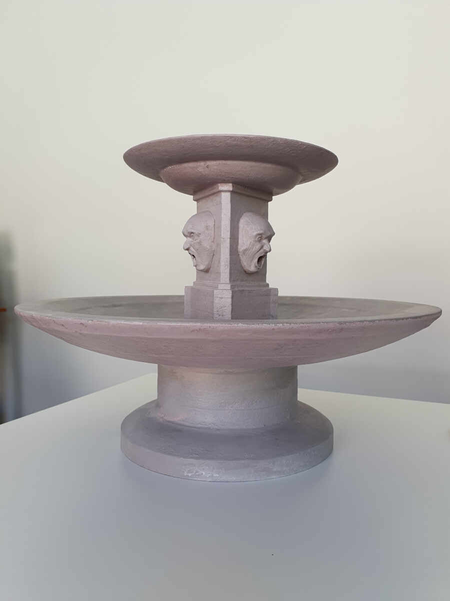
As a consequence, for my final project I decided to challenge myself with a scenography element for my theater company "La Compagnie de L'hydre", a fountain I named: THE FOUNTAIN OF DESPAIR. This fountain is inspired by Shakespeare's bloodiest play and a rewriting of it by Heiner Mûller: ANATOMY TITUS. For my project I decided to build a scaled replica as a manufacturing proof of concept for a latter bigger version.
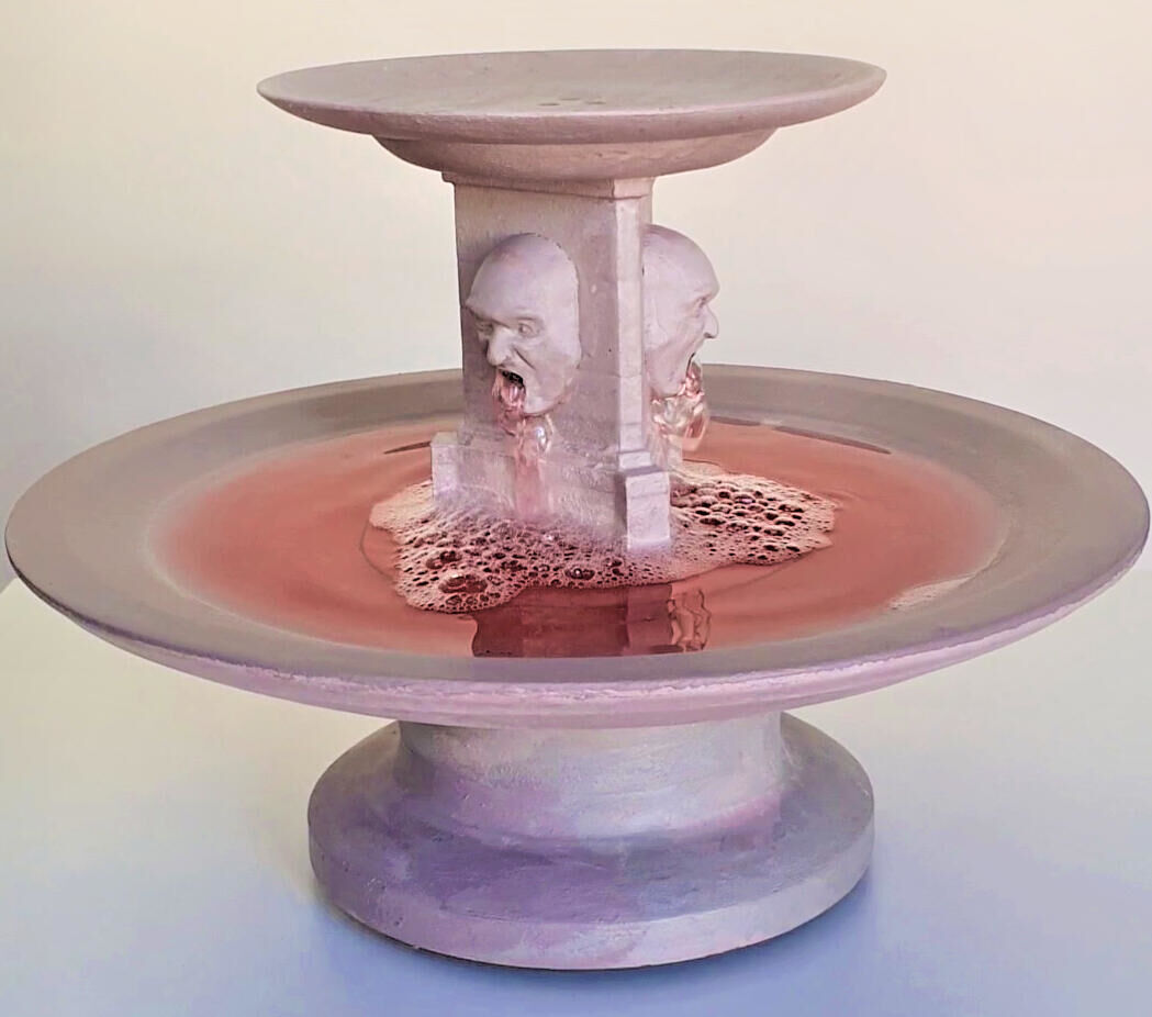
From an esthetical point of view, the fountain pictures the decline of the empire. The fountain is old fashion and three heads spit the blood of innocents. The heads were done by molding and casting and the external finished shape was made of 23 MDF parts 3D milled with a CNC machine. The water dispenser and container hidden inside fountain were made by 3D printing. Then the fountain was made waterproof by covering it with a layer of polyurethane and two layers of acrylic painting.
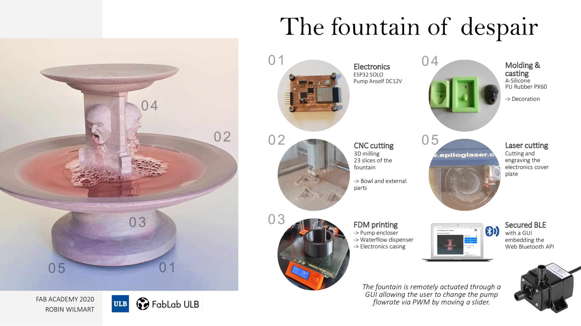
The main challenge with the elements of a scenography that need to be actuated is that most of the time the actuation must be done remotely. It is unconceivable that the general operator comes on stage to manually switch on the fountain. This would completely ruin the scenographical effect unless it is intentional. The remote control was therefore made possible by using the ESP32 SOLO with the Bluetooth Low Energy protocol. The connection to the fountain is secured and the actuation is made through a GUI embedding WEB Bluetooth API. The electronics and the Bluetooth antenna are hidden beneath the water tank in the fountain base.
In the following sections I will provide the list of materials and I'll explain the different stages of the conception and fabrication.

This work is licensed under a Creative Commons Attribution-NonCommercial-ShareAlike 4.0 International License.
List of materials
To make that this project I needed :
| # | Materials | Qty | Price |
|---|---|---|---|
| 1 | A 18mm x 1220mm x 2440mm MDF Board | 1 | ≈ 20 € |
| 2 | PLA Filament | N/A | ≈ 4 € |
| 3 | M3 Brass Threaded Insert | 15 | 0.167 € / unit |
| 4 | M3x16mm Hex Socket Head Cap Screw |
6 | 0.30 € / unit |
| 5 | M3x10mm Hex Socket Head Cap Screw |
4 | 0.28 € / unit |
| 6 | M3x50mm Hex Socket Head Cap Screw |
3 | 0.44 € / unit |
| 7 | M3x8mm Black Nylon Plastic Cross Pan Head Machine Screws |
2 | 0.20 € / unit |
| 8 | Anself Brushless DC Pump - DC12V 4.2W | 1 | ≈ 12 € |
| 9 | A 250x250x50mm block of High Density Polyurethane Foam |
1 | ≈ 15 € |
| 10 | Elite Double 32 - Zhermack VINYLPOLYSILOXANE - 1kg.+1kg. |
1 | ≈ 65 € |
| 11 | PVA Mould Release Agent 200ml | 1 | ≈ 5 € |
| 12 | Xencast PX60 Medium Flexible Polyurethane Rubber - 1kg Kit |
1 | ≈ 20 € |
| 13 | Waterproof wood glue | 1 | ≈ 8 € |
| 14 | Acrylic painting (white, black, yellow and red) | 4 | ≈ 2 € / unit |
| 15 | Rubber O-Ring 1/4in O.D | 3 | ≈ 2.40 € / 50 units |
For the electronics I needed :
| # | Components/Materials | Qty | Price |
|---|---|---|---|
| 1 | A single sided copper clad PCB board | 1 | ≈ 0.70 € |
| 2 | ESP32-SOLO-1 | 1 | ≈ 3.10 € |
| 3 | Tactile Switch | 1 | ≈ 0.70 € |
| 4 | DC Power Supply Jack Socket Female Panel Mount Connector 3-Pin 5.5 x 2.1mm |
1 | ≈ 1.30 € |
| 5 | Resistors (100Ω - 1kΩ - 10kΩ) | 4 | ≈ 0.20 € / unit |
| 6 | Capacitors (1µF - 0.1µF) | 2 | ≈ 0.20 € / unit |
| 7 | LEDs (Green, Red) | 2 | ≈ 0.30 € / unit |
| 8 | Rectifier Diode 400V 1A | 1 | ≈ 0.40 € / unit |
| 9 | PCB headers SMD | N/A | ≈ 0.80 € / unit |
| 10 | Serial header SMD | 1 | ≈ 0.70 € |
| 11 | Voltage regulator - UA78M33CKVURG3 | 1 | ≈ 0.60 € |
| 12 | MOSFET - IPD135N03L G | 1 | ≈ 0.62 € |
| 13 | 12V DC Power Supply | 1 | ≈ 5 € |
| 14 | Rubber O-Ring 1/4in O.D | 4 | ≈ 2.40 € / 50 units |
This work is licensed under a Creative Commons Attribution-NonCommercial-ShareAlike 4.0 International License.
Conception
The fountain was supposed to be horrifying. Originally the play director, Nathalie Huysman, wanted tripe exiting from the heads. Consequently I made this first drawing.
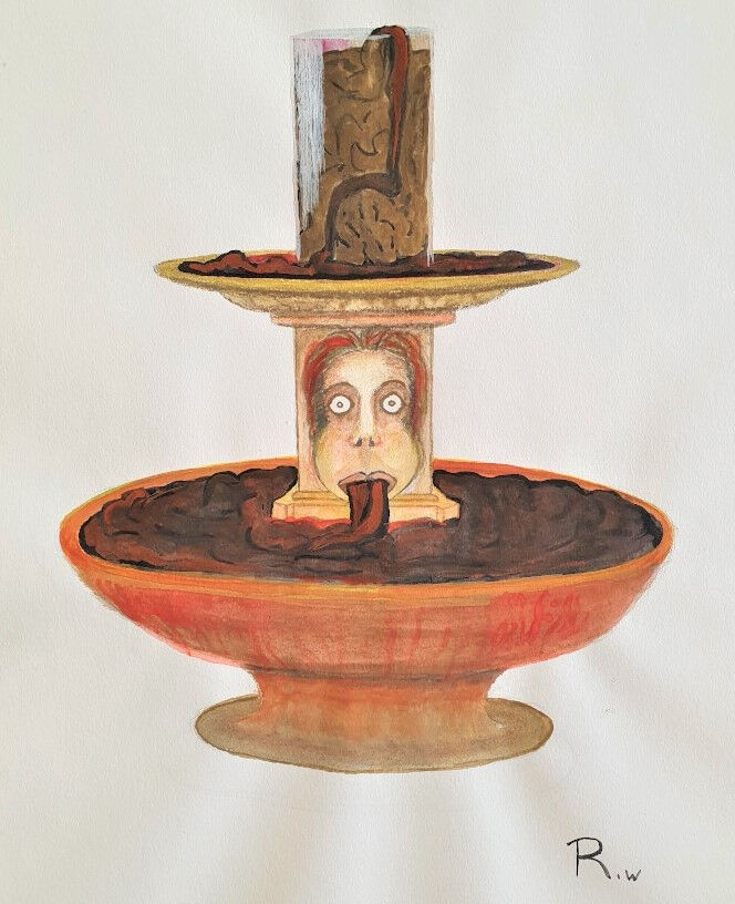
Drawing of the fountain of despair
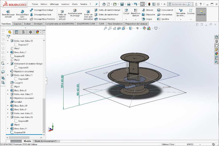
For technical reasons and because the smell would be hardly bearable by the spectators we decided to change tripe for blood. I designed the fountain on SolidWorks by integrating some details borrowed to classical architecture and the magnificent painting of Constant Montald, The Fountain of Inspiration.
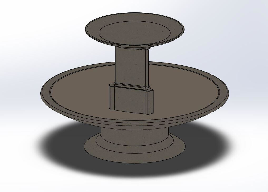
First CAD of the fountain on SolidWorks
Once I finished to design the external envelop of the fountain, I started to dig inside it to create space for a water tank and the distribution system. At that point I checked the water volume that would be available. With a pump moving 240L water per hour, i.e. 4L/min, a volume of 2.5 liters is sufficient to provide enough water to the pump (read this subsection to know how to check the water volume).
Then, I divided the fountain into two parts to provide the access to mount the pump. Both parts will be assembled with screws and a rubber seal in between to avoid leakage.
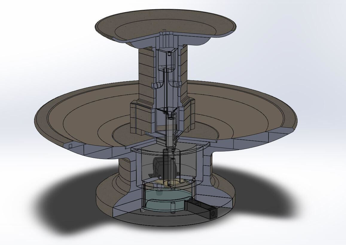
Cut of the fountain
Afterwards I divided these two parts into several parts: a water tank, a water dispenser and an electronics case that will be fabricated by 3D printing and several finishing slices that will be 3D milled. For more details on the assembly have a look on the following video.
Assembly of the fountain of despair
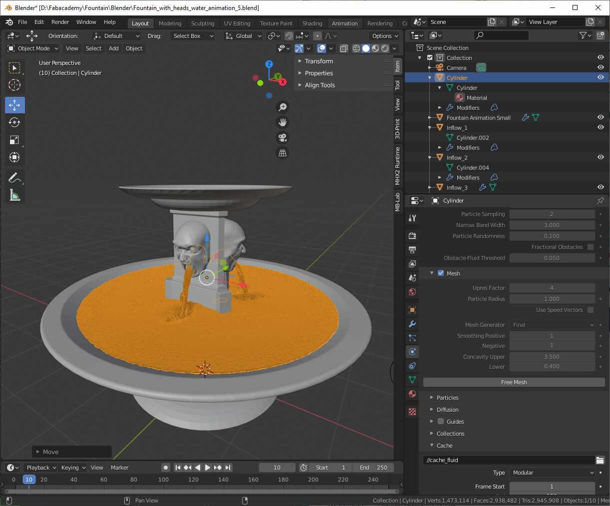
Finally I exported the file in the standard STL format and I used it into Blender to add the heads made during WEEK 16 - Molding and Casting and create a 3D render with Eevee. To add water in the fountain I used MantaFlow fluids and smoke simulation. I learned to do it by watching this video. Then, to denoise my image I followed this tutorial.
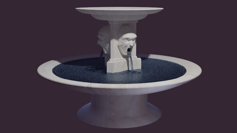
3D render of the fountain of the despair with Eevee
Since the 3D render was quite time consuming with Eevee, I used Cycles, a faster although less realistic render engine to make the animation.
Animation of the fountain of despair with Cycles
How to make the animation in Blender?
To make the animation with the water/blood simulation I followed this tutorial. First I imported the STL file of the fountain into Blender 2.82 then I added a cylinder to define the simulation domain. In the Physics Properties tab I enabled physics for Fluid then I chose Domain as a type and Liquid as domain type and I set the resolution divisions to 200.
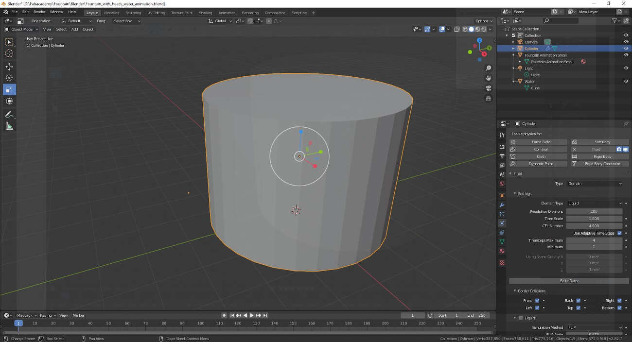
I also set the last frame to 150.
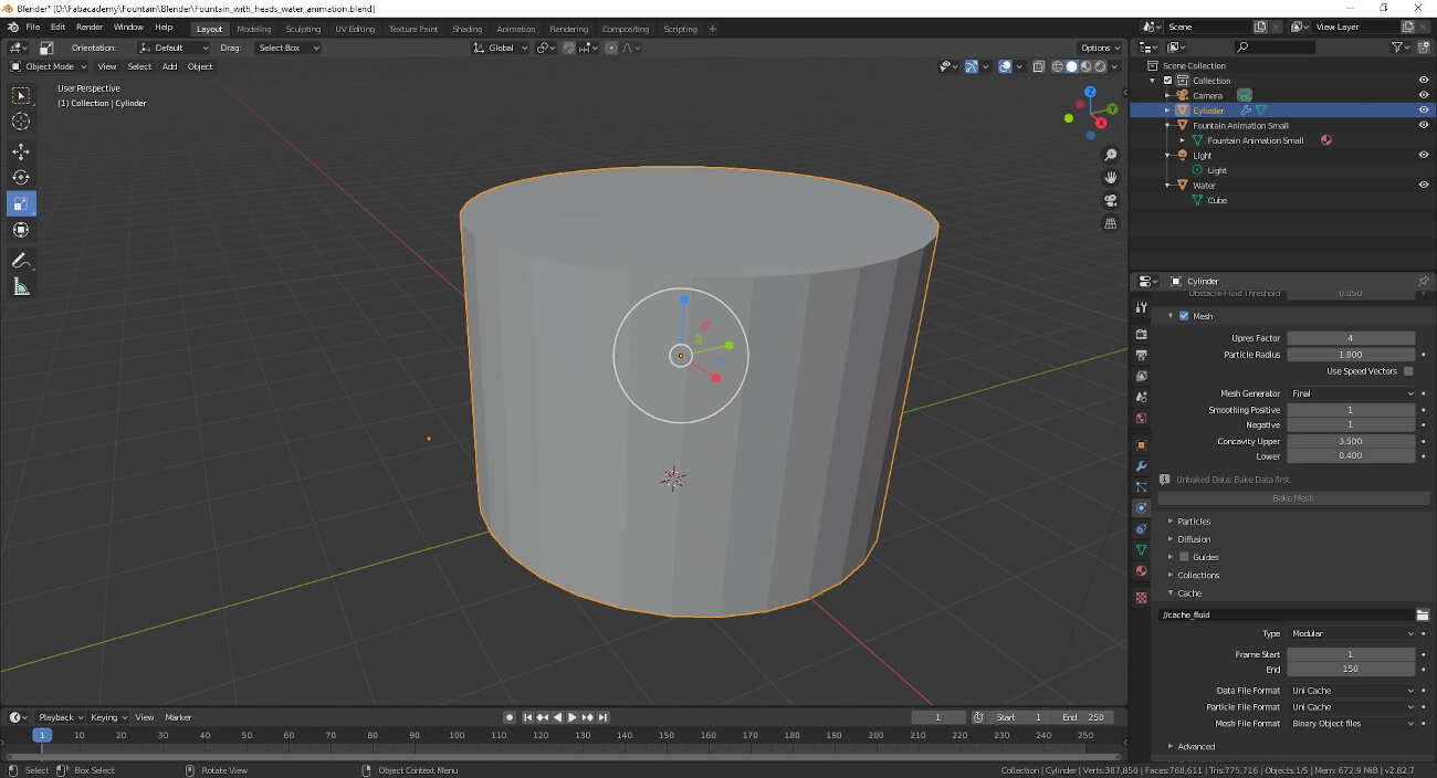
Then in the Object Properties tab under Viewport Display I changed the display to Wire.
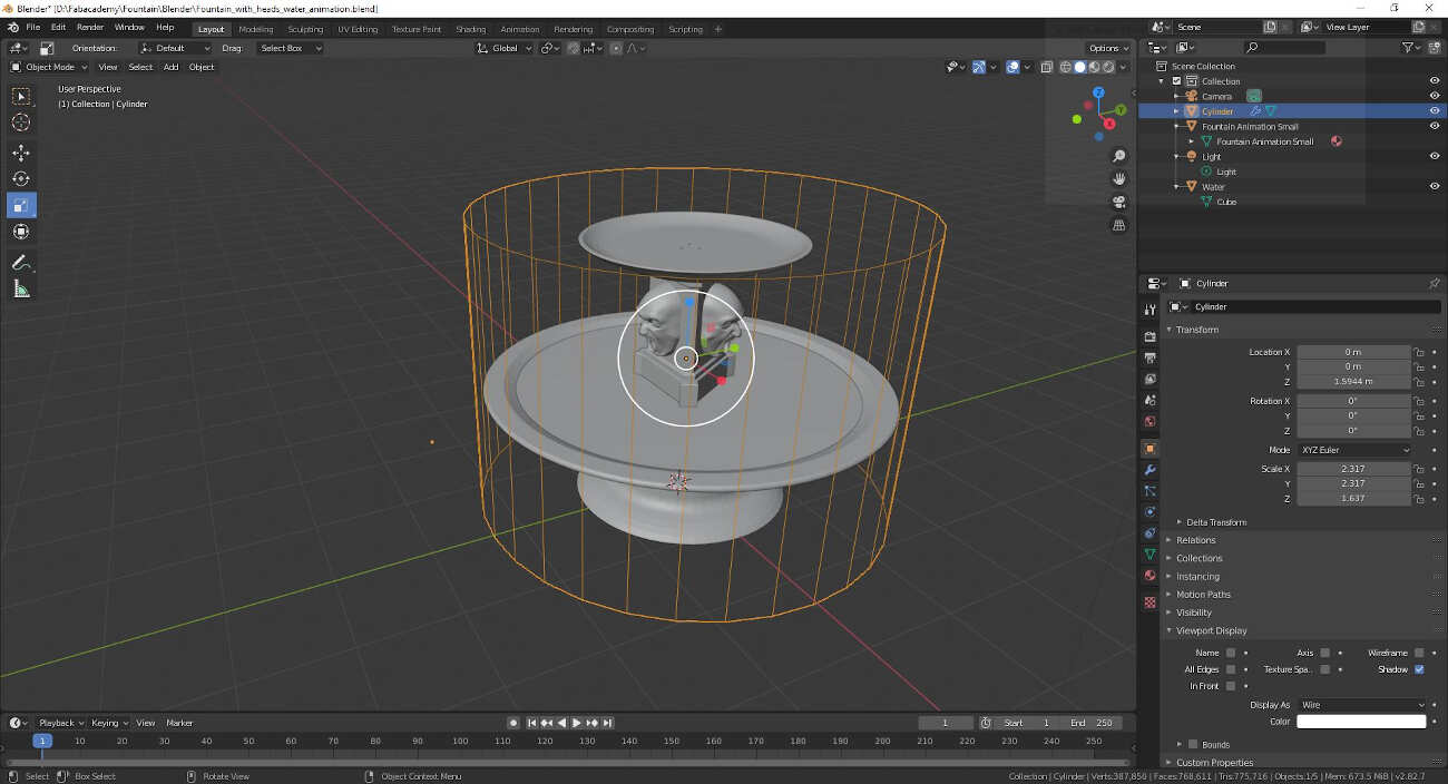
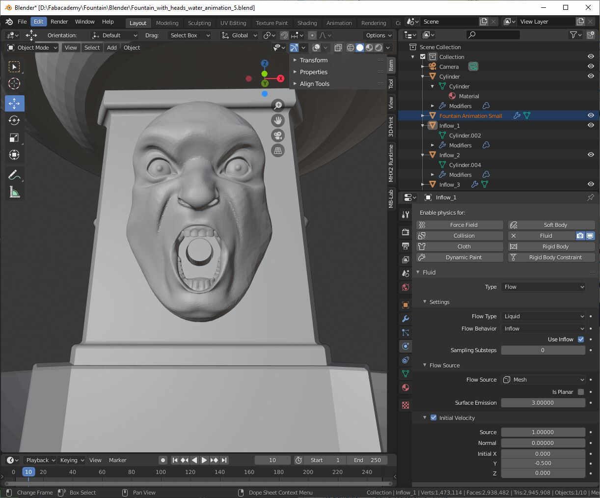
Afterwards I added three cylinders, one inside of each mouth. In their Physics Properties tab I enabled physics for Fluid. As a type I chose Flow then Liquid as Flow type and Inflow as Flow Behavior. As initial velocity I set the Y axis to -0.5.
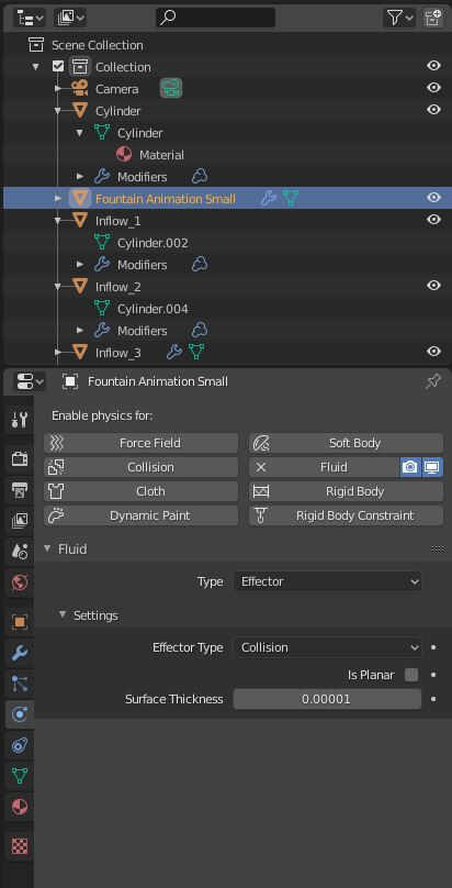
I selected the fountain I set it as an obstacle. To do that I enabled physics for Fluid and I set Effector as Type and Collision as Effector Type.
Finally I came back to the cylinder Physics Properties and I clicked on Bake Data and then Bake Mesh.
Adding the textures and making the animation can easily be done by following, as I've done, the rest of the above tutorial and this one about UV Unwrapping.
How to check the available water volume?
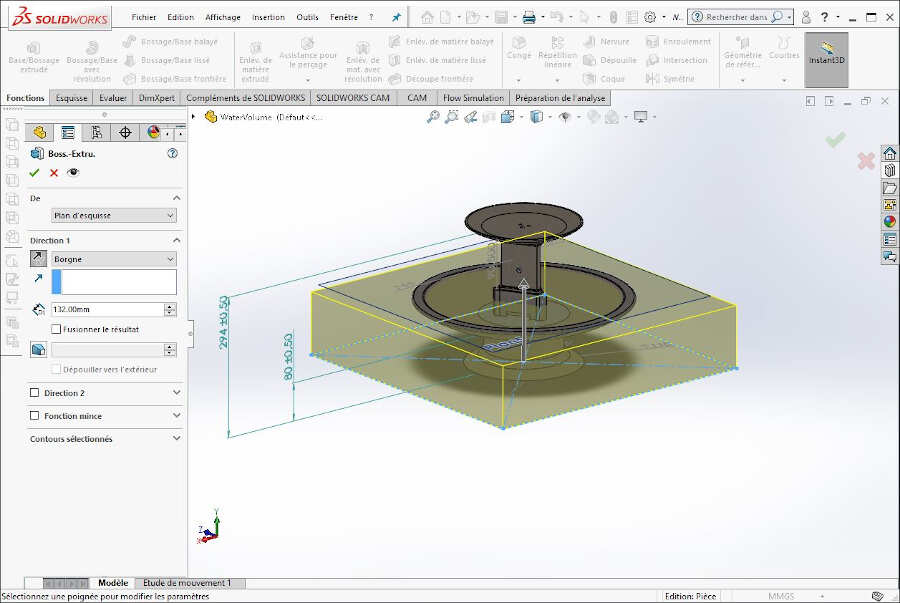
To compute the internal volume of the fountain I made good use of this SolidWorks tutorial. I first made a sketch at the base of the fountain.
Then I extruded the sketch into 3D up to a reasonable level for the water inside the fountain.
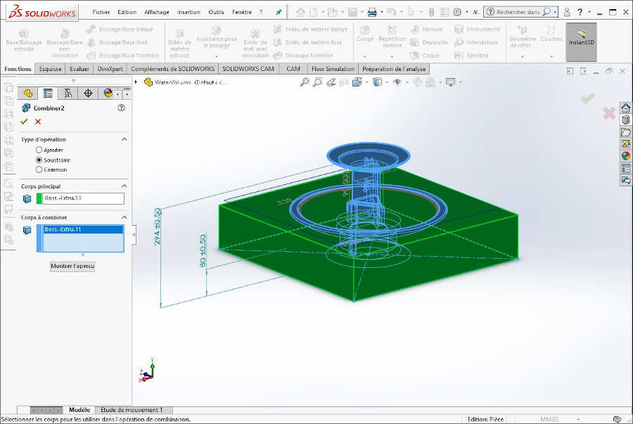
Under Insert->Features->Combine I applied the Combine feature.
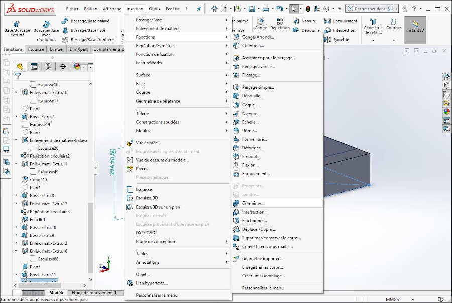
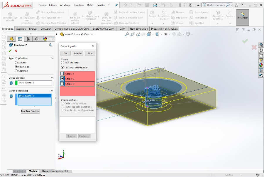
I selected Subtract, the main body and the bodies to combine as show on the pictures bellow and I validated my choices.
In the pop-up window I chose to keep only the body consisting in the water inside the fountain.
Finally under the tab Evaluate I clicked on Mass Properties.
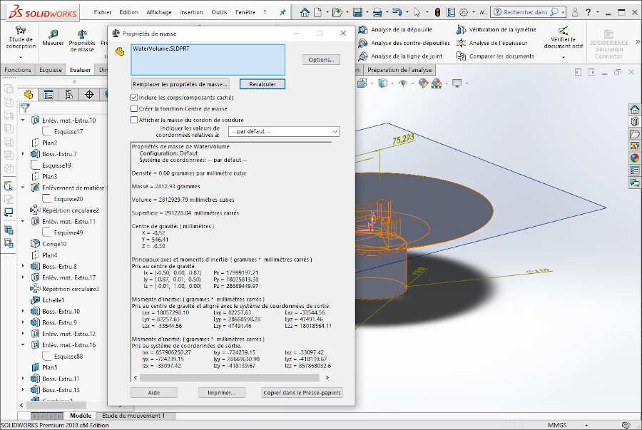
I evaluated the water volume to 2812929.79 mm3 = 2812.9 cm3 = 2.8 dm3 which is equivalent to 2.8L of water.
Electronics
To design my electronic circuit I decided to work on Autodesk Eagle. As I planned to use the ESP32-SOLO-1 to control the fountain on remote, I first drew the footprint and the symbol of the component.
To do it I followed a very useful series of tutorial to create a Package in Autodesk Eagle:
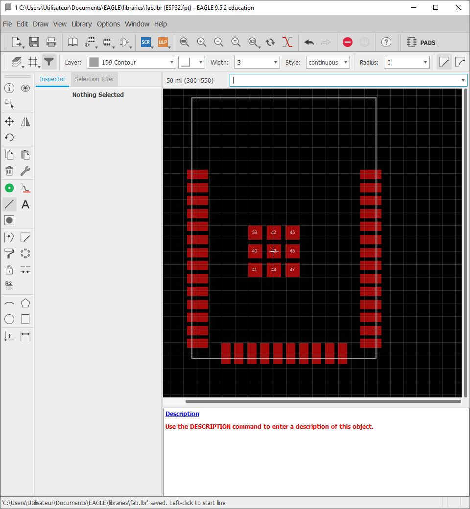
Footprint of the ESP32-SOLO-1
Since the ESP32-SOLO-1 needs 3.3V and the pump requires 12V DC, I planned to provide a 12V DC power supply through a jack socket. Then, the 12V DC is transformed into 3.3V with the voltage regulator UA78M33CKVURG3. The datasheet of the latter recommends to add two capacitors, one at the input and one at the output. As a first check I added a green led at the voltage regulator output to be sure that it actually delivers 3.3V. To be able to program the ESP32 I added a serial port, a 3 pinhead connector and a reset button as shown in the example provide during the week about Networking and Communications.
The datasheet of the ESP32 (Table 3: Strapping Pins) also mentions that GPIO0 can be used for the configuration of the booting mode.
| BOOTING MODE | |||
|---|---|---|---|
| Pin | Default | SPI Boot | Download Boot |
| GPIO0 | Pull-up | 1 | 0 |
| GPIO2 | Pull-down | Don't-care | 0 |
This explains why GPIO0 can either be connected to ground or not on this board.

Finally, to control the pump I used GPIO27. I connected it to a MOSFET that enable the controllability of the pump with PWM signals. Although the MOFSET - IPD135N03L G already integrates a rectifier diode I added an extra one to protect the electronics from the currents that might be induced by the pump solenoid. Then, to be able to program the ESP32-SOLO-1 without being forced to connect the pump, I added a red LED right after GPIO27 to be able to check signaling.
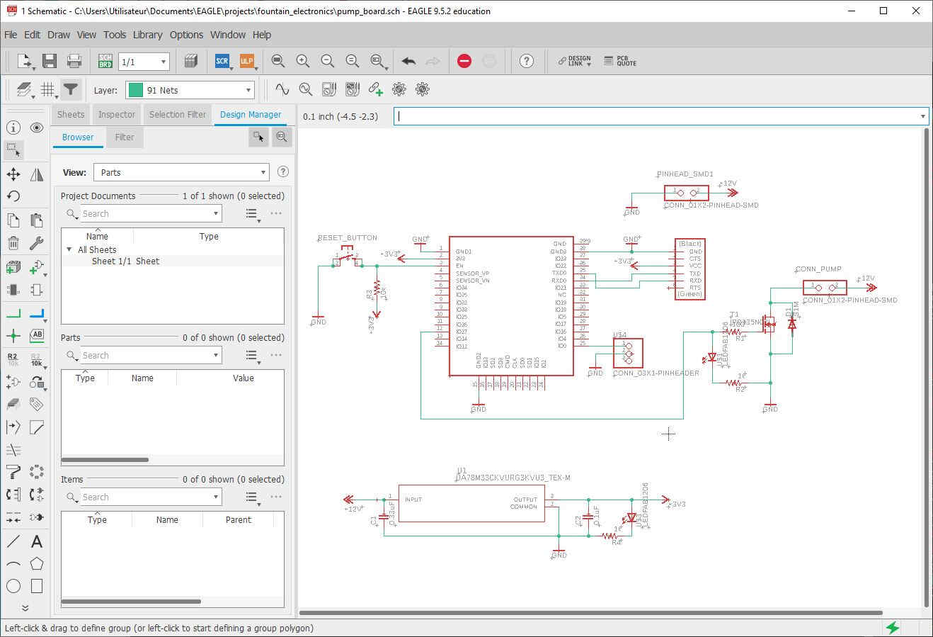
Schematics of the PCB
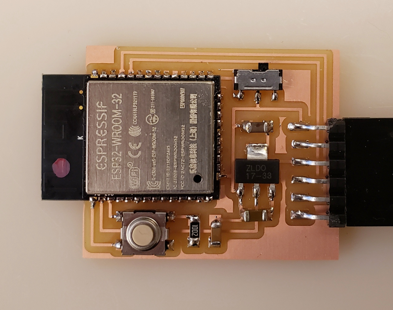
Afterwards I placed the components on the board and I made my best to optimize the space to make the board as small as possible. I cut the PCB edges in such a way that the Bluetooth/WIFI antenna would not remain on the PCB. This little modification might significantly improve the signal reach.
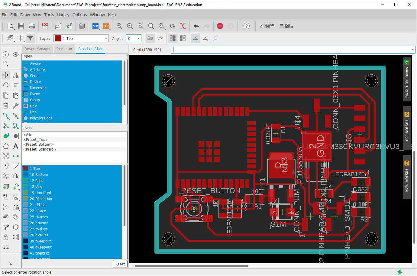
PCB board
Then I loaded the EAGLE files in the BANTAM TOOLS and I selected a 1/64in flat end mill to engrave the circuitry and a 1mm one to cut the holes and the PCB outlines.
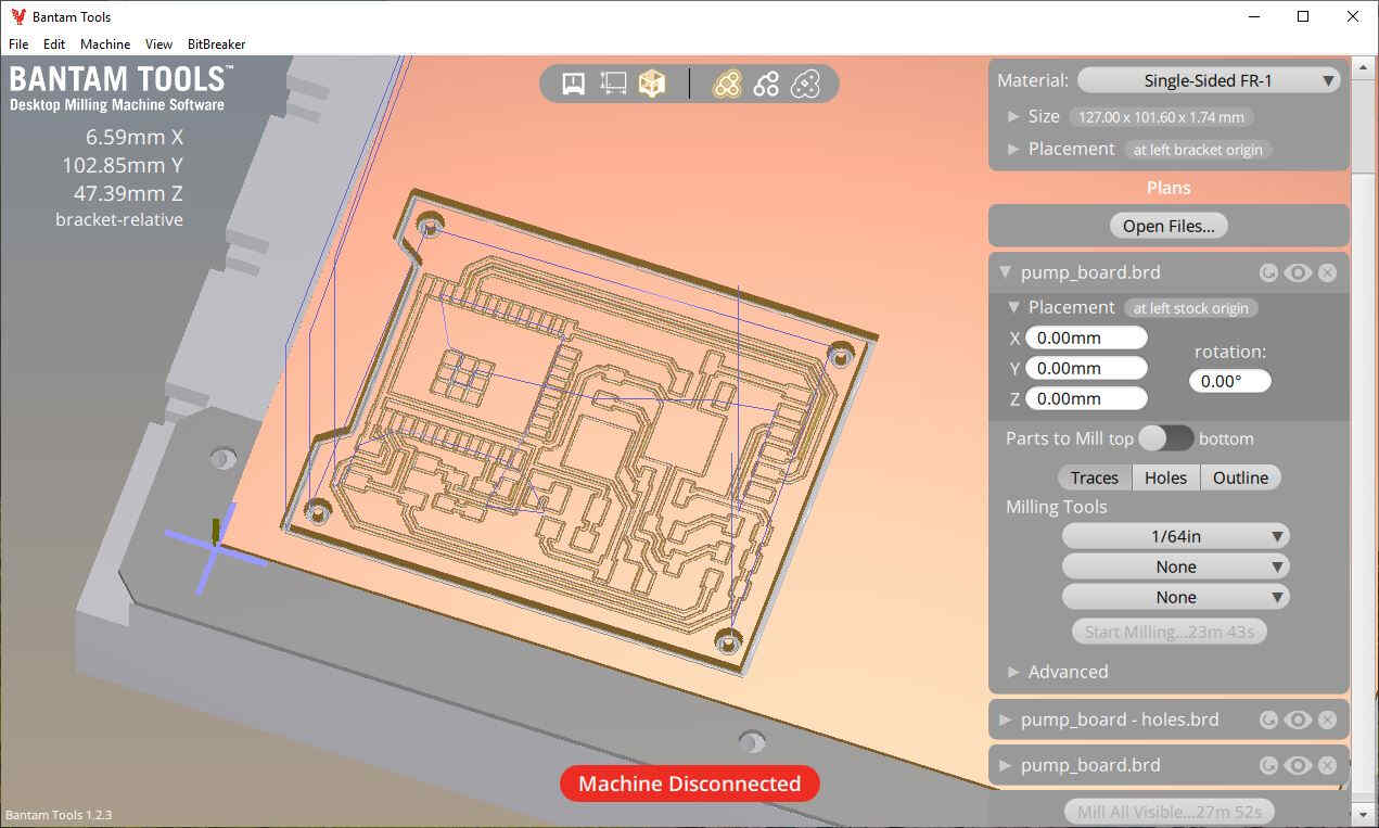
Once the milling operations were set, I used the Bantam Tools Desktop PCB Milling Machine as show in the following videos. First the circuitry...
PCB milling
... then the holes and the edges.
Cutting the PCB contours
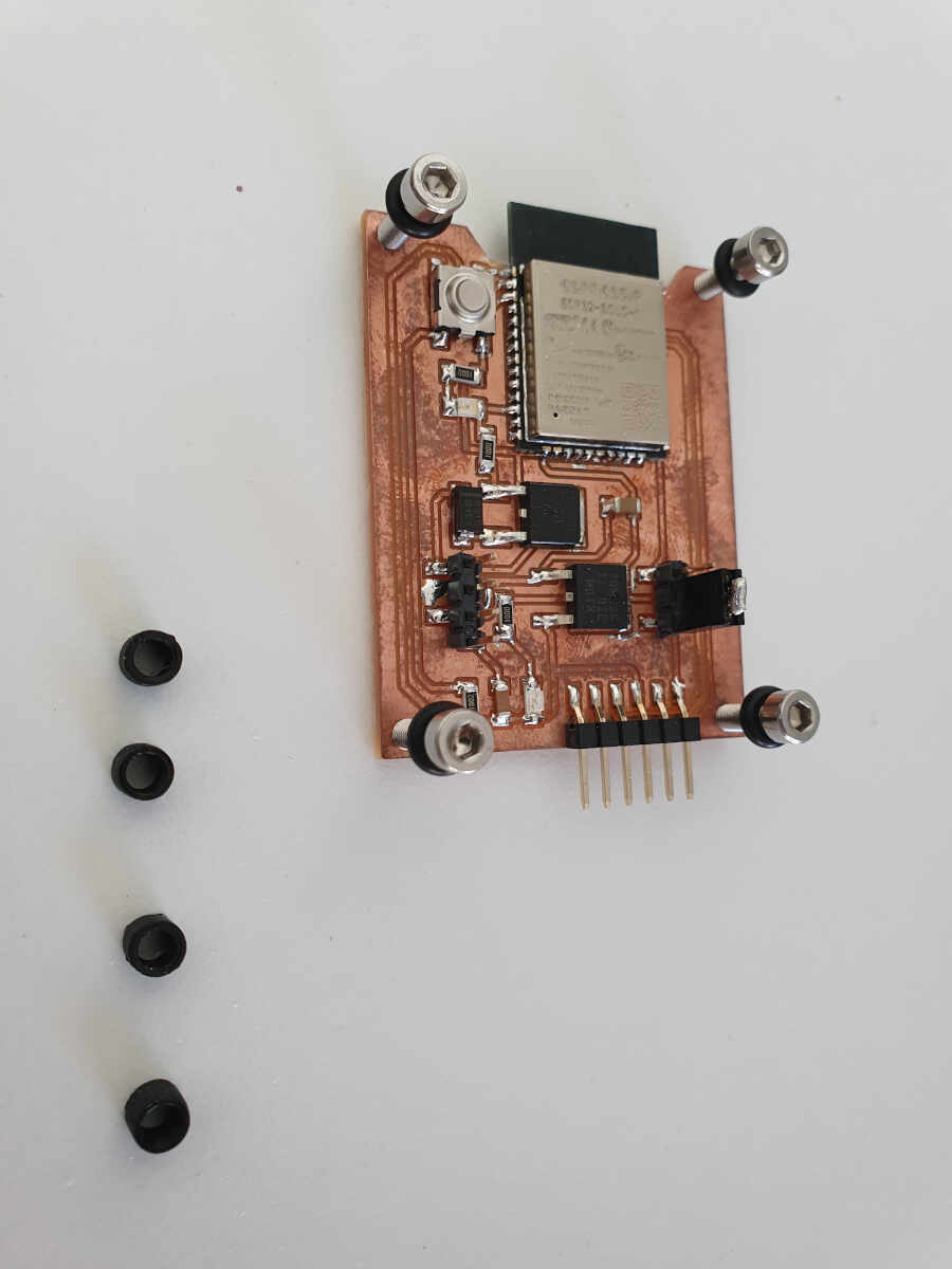
Finally I stuffed the boards with the all the electronics components.
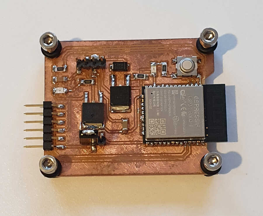
Stuffed PCB board
Retrospectively it would have been better to put a chemical capacitor at the entry of the voltage regulator instead of the one that I used, in particular because the 12VDC is shared with the pump but for this application a capacitor of 1 µF is enough.
ESP32 Programming
At that point of my work my board was not done yet because I was waiting for the delivery of the ESP32-SOLO-1. Nevertheless I had two different modules at my disposal: the Adafruit AirLift – ESP32 WiFi Co-Processor Breakout Board and the SparkFun Thing Plus - ESP32 WROOM. I started by programming the SparkFun Thing Plus - ESP32 WROOM. I found it a valuable temporary solution to test the capabilities of the ESP32 because I wasn't sure of how to connect alone the ESP32 to my computer to program it. I'll leave that for later. At least I could test a basic code on it just to get familiar with the ESP32.
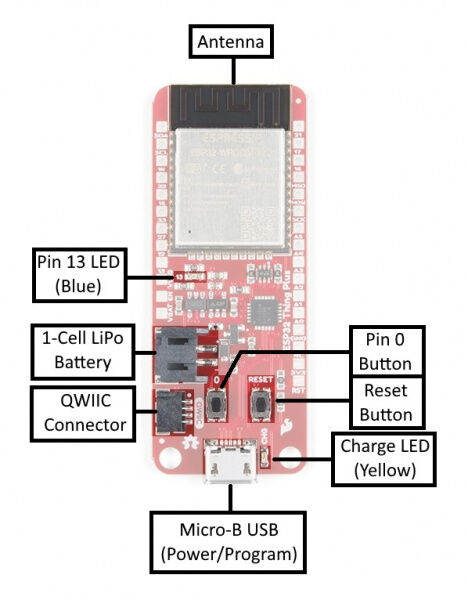
Picture of the SparkFun Thing Plus - ESP32 WROOM
As a development environment I chose Arduino IDE. The first thing I had to do was to set the development environment to enable the ESP32 programing. I followed this procedure. First I installed the library package_esp32_index.json in the Arduino IDE then I installed the USB drivers. Under File I selected Preferences.
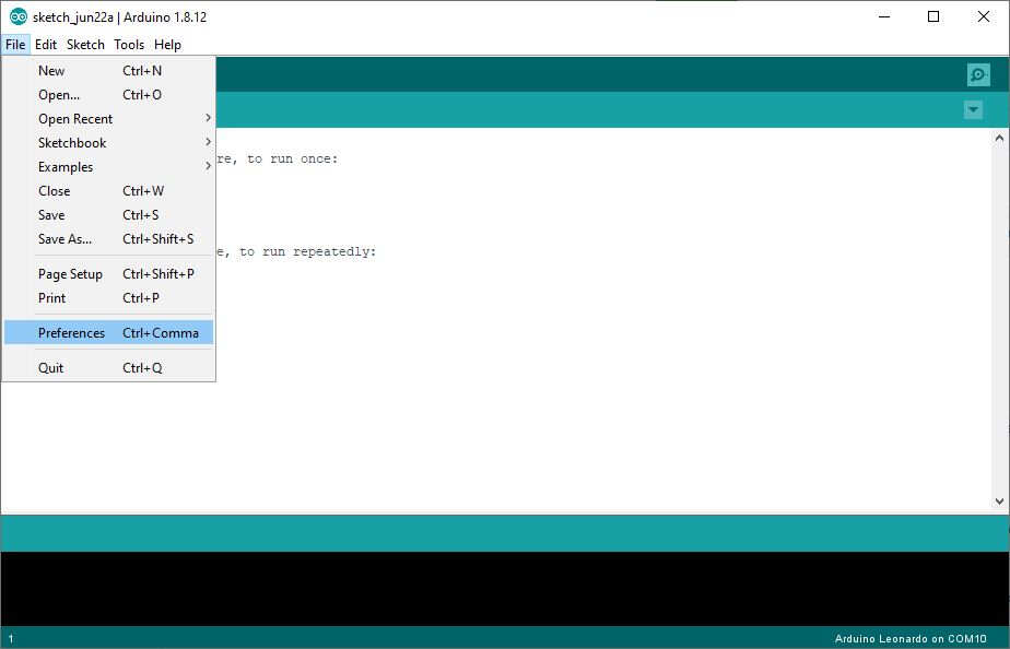
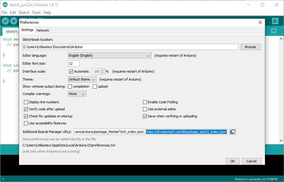
Then under Additional Boards Manager URLs, I added the following link to the ESP32 library: https://dl.espressif.com/dl/package_esp32_index.json.
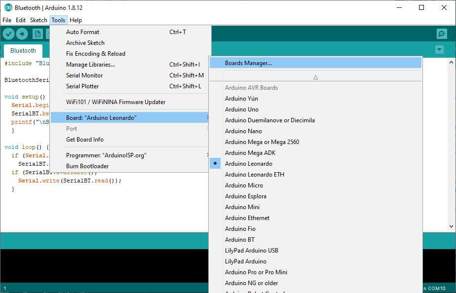
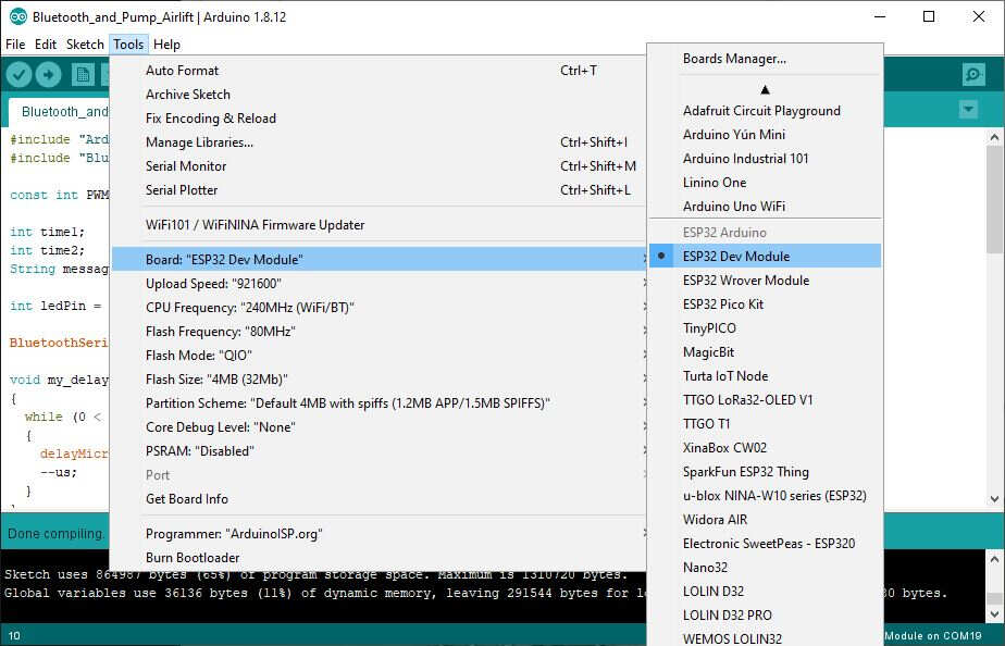
Then I opened the boards manager: Tools -> Board: "xxx" -> Boards Manager....
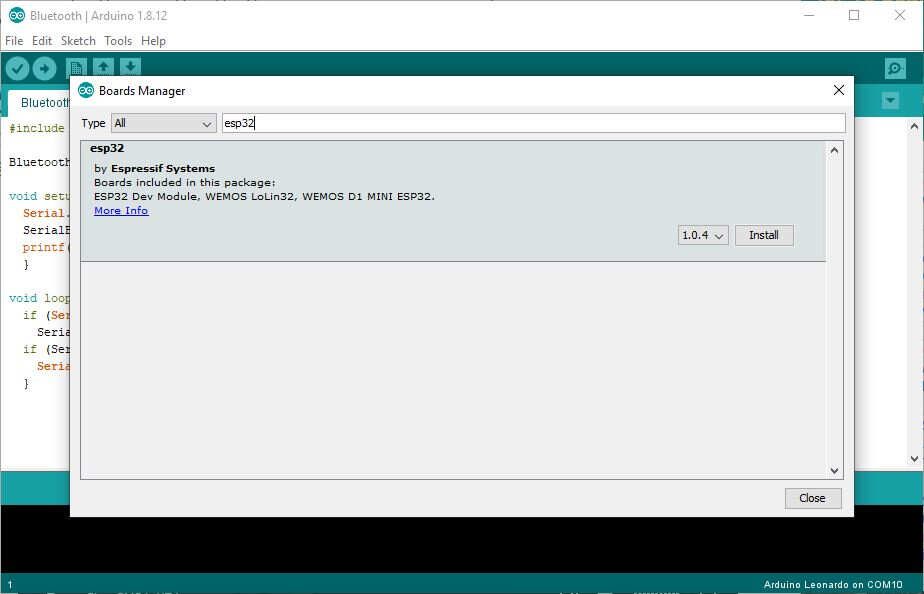
I looked for the ESP32 library ...
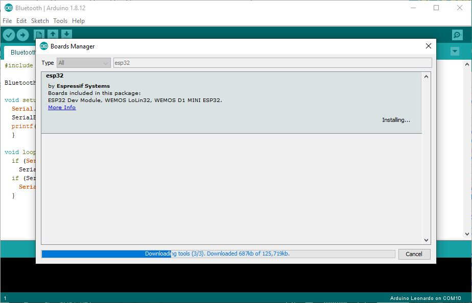
... and I installed it.
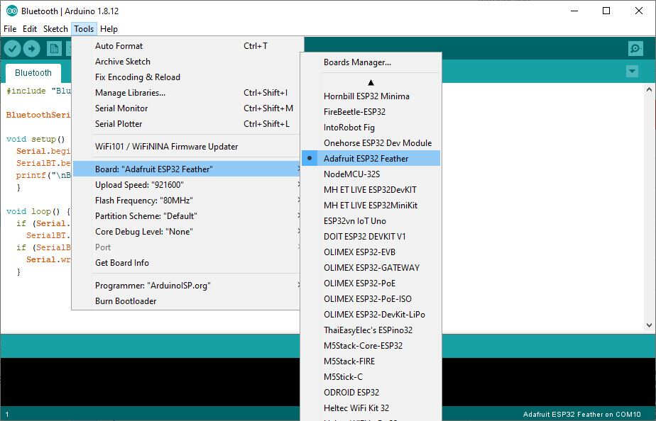
Then I selected the Adafruit ESP32 Feather board.
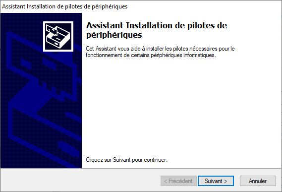
Another thing I had to do to be able to load anything on the ESP32 was to install the CP210x USB to UART Bridge Virtual COM Port (VCP) drivers.
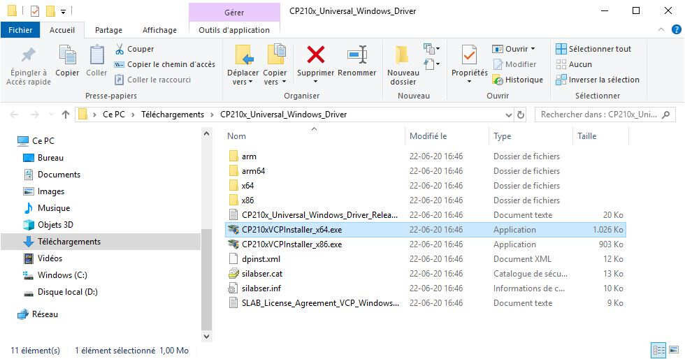
I followed the installation wizard.
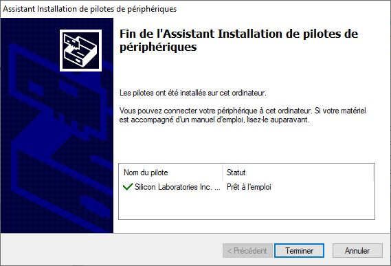
After installing the drivers I had to restart my computer.
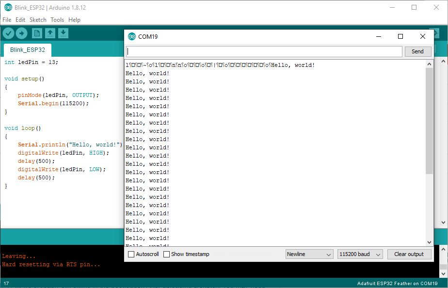
To be sure that the Arduino IDE was properly set up I first tested the easiest code I could find. As we know from the ESP32 Thing Plus Hookup Guide a blue LED is connected to PIN13. The purpose of this code is to make it blink and to test the serial connection.
int ledPin = 13;

void setup()
{
    pinMode(ledPin, OUTPUT);
    Serial.begin(115200);
}

void loop()
{
    Serial.println("Hello, world!");
    digitalWrite(ledPin, HIGH);
    delay(500);
    digitalWrite(ledPin, LOW);
    delay(500);
}
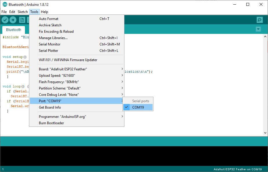
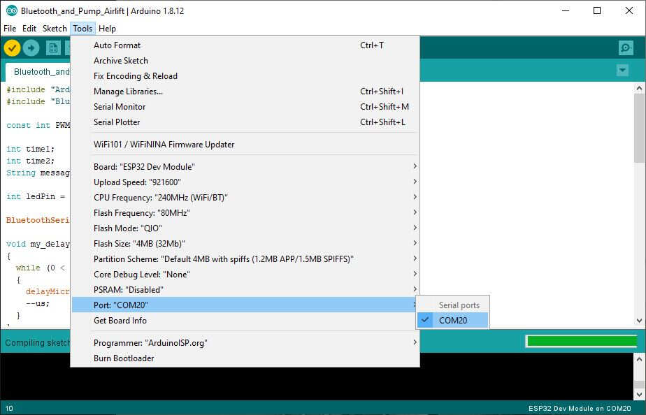
I selected the appropriate PORT, here "COM19".
And after loading the upper code I got this expected result on the serial monitor and the led blinked.
Then, knowing that the Arduino IDE was properly set up, I loaded the easiest code I could find to test Bluetooth. At this stage it is worth to remind that Bluetooth has 2 versions: Bluetooth Classic and Bluetooth Low Energy (BLE). The code I used is an implementation of Bluetooth Classic. BLE is much harder to code, it will be discuss later.
#include "BluetoothSerial.h"

BluetoothSerial SerialBT;

void setup() {
  Serial.begin(115200);
  SerialBT.begin("MyESP32"); //Pick the name you want for your Bluetooth device
  printf("\nBluetooth is ready for pairing and serial communication\n\n");
  }

void loop() {
  if (Serial.available())
    SerialBT.write(Serial.read());
  if (SerialBT.available())
    Serial.write(SerialBT.read());
  }
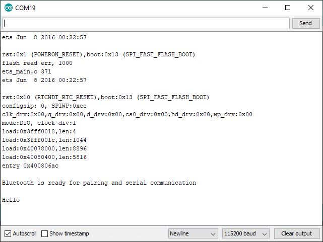
Then I installed BLE Scanner: Read, Write, Notify and Serial Bluetooth Terminal on my smartphone to see if I can pair it with the ESP32 and check that the code is working fine. Once connected to the ESP32 with my phone the serial monitor gave some feedback to acknowledge that the pairing was done properly and I set a message Hello from my phone to the ESP32 as shown in the following picture.
Afterwards I coded the part with the activation of the pump. I decided for coding PWM activation of the pump to have a lit bit more control on the flow rate in comparison with ON/OFF activation. I set a constant for the PWM period then I used the message from the Bluetooth connection to activate the pump in a range between 0 and 20. I used the command toInt() to convert the String message into an integer.
#include "Arduino.h"
#include "BluetoothSerial.h"

const int PWM_period=10000;

int time1;
int time2;
String message;

int ledPin = 13;

BluetoothSerial SerialBT;

void my_delay_us(int us)
{
  while (0 < us)
  {
    delayMicroseconds(1);
    --us;
  }
}

void callback(esp_spp_cb_event_t event, esp_spp_cb_param_t *param){
  if(event == ESP_SPP_SRV_OPEN_EVT){
    Serial.println("Client Connected");
  }
}

void setup() {
  Serial.begin(115200);

  SerialBT.register_callback(callback);

  if(!SerialBT.begin("Fountain_BLE")){
    Serial.println("An error occurred initializing Bluetooth");
  }else{
    Serial.println("Bluetooth initialized");
  }

  pinMode(ledPin, OUTPUT);
}

void loop() {
  if (Serial.available())
    SerialBT.write(Serial.read());
  if (SerialBT.available()){

    // read the incoming byte:
    message = SerialBT.readString();
    int MESSAGE = (message).toInt();

    if (MESSAGE>=0 && MESSAGE<=20){
     time1 = (MESSAGE*PWM_period)/20;
     time2 = PWM_period-time1;
     Serial.println(time1);
     Serial.println(time2);
    }
  }

  digitalWrite(ledPin, HIGH);
  my_delay_us(time1);
  digitalWrite(ledPin, LOW);
  my_delay_us(time2);

}
Then, to learn how to program the ESP32 without using a card embedding a USB port, I used the Adafruit AirLift module.
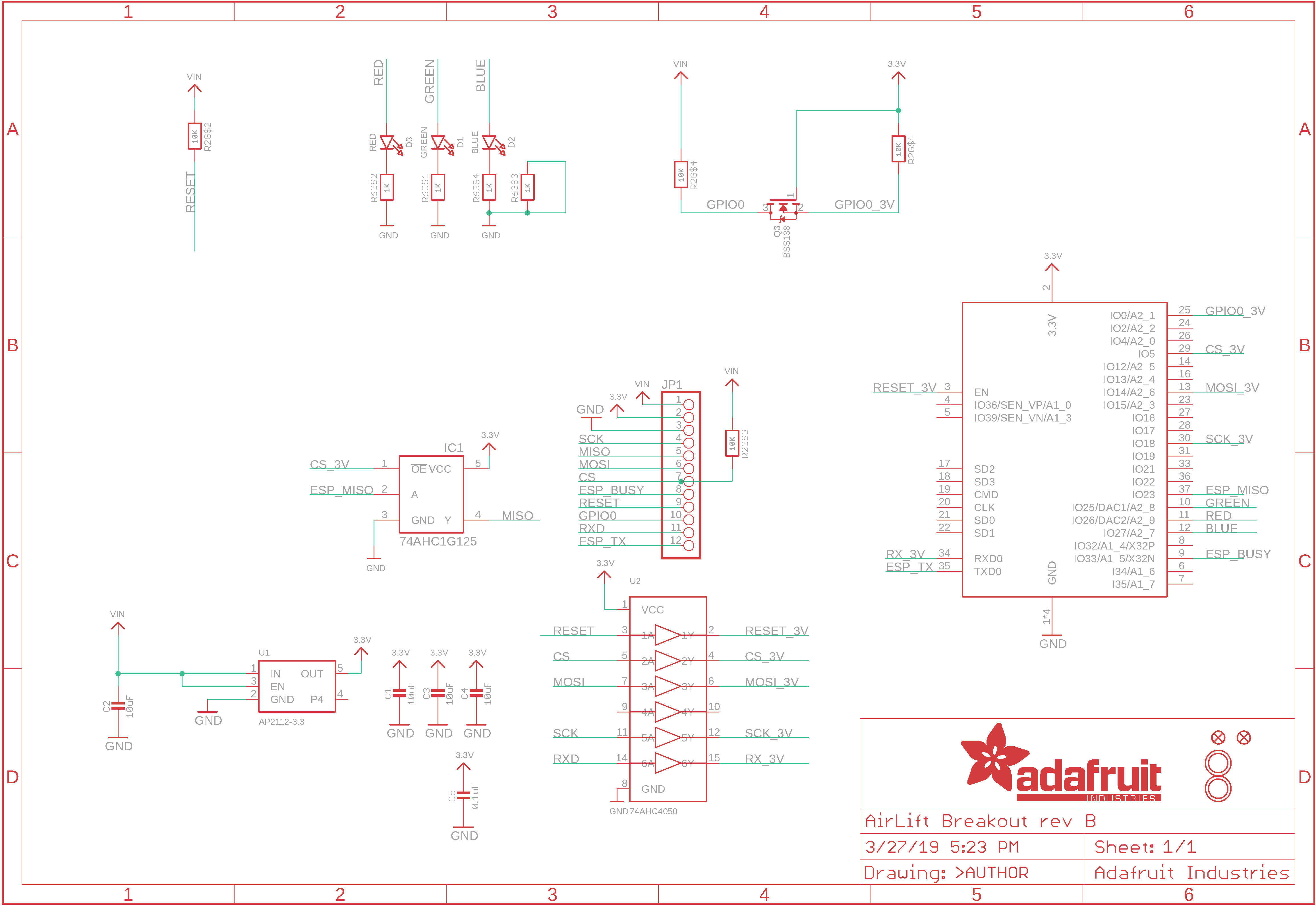
I compared its schematics with the circuit drawings provided by the FABACADEMY and I found that I had access to the same pins on both cards. As the solution provided by the FABACADEMY was using a 3.3V FTDI serial port to program the ESP32, I would need a 3.3V FTDI USB to Serial Converter such as the one of the picture to connect the ESP32 to my computer USB port. Although I could have built such a converter by myself with the drawings provided during the week about Embedded Programming ( look for "hello.D11C.serial.3V3" ) I used a commercialized one because of lack of time.
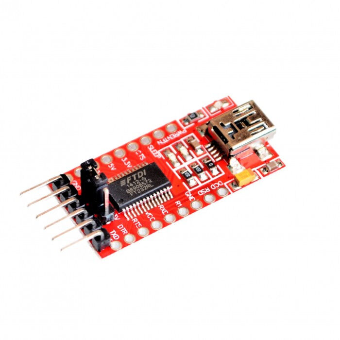
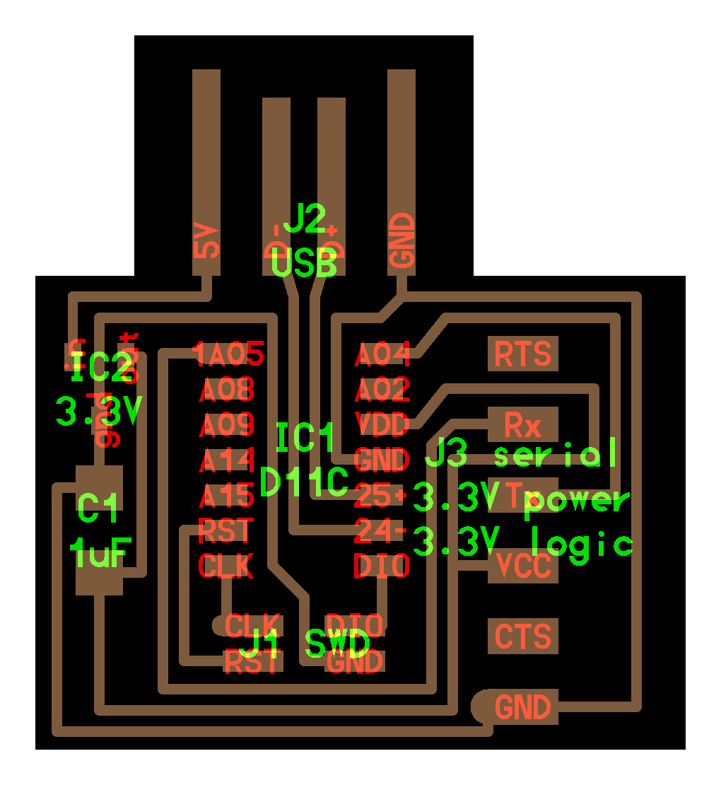
FTDI USB to Serial Converter
Schematics of a DIY 3.3V FTDI USB to Serial Converter
I connected Rx to Tx, Tx to Rx, GND to GND and 3V3 to 3V3. Make one hundred percent sure that the USB to Serial converter is set to 3v3 otherwise you might damage the ESP32. Make also sure that Vin pin of the Airlift module is connected to 3V3 otherwise you might experience the following error: Brownout detector was triggered.
I consequently changed the board to ESP32 Dev Module.
I also changed the port number.
Finally I used the Bluetooth Low Energy which is more appropriate for my application. My code is based on Neil Kolban example BLE_uart. I modified it to add more capabilities such as the activation of the pump. To be able to do it I needed the function c_str() to convert a list of char into a String. I also added some code lines based on a code written by choichangjun to implement security with a password for pairing. I also had to learn a bit more about the inheritance concept of a class to understand what was written.
#include <BLEDevice.h>
#include <BLEServer.h>
#include <BLEUtils.h>
#include <BLE2902.h>

BLEServer *pServer = NULL;
BLECharacteristic * pTxCharacteristic;
bool deviceConnected = false;
bool oldDeviceConnected = false;
uint8_t txValue = 0;

const int PWM_period=10000;

String message = "0";
int time1;
int time2;

int ledPin = 27;

void my_delay_us(int us)
{
  while (0 < us)
  {
    delayMicroseconds(1);
    --us;
  }
}

// See the following for generating UUIDs:
// https://www.uuidgenerator.net/

#define SERVICE_UUID           "6E400001-B5A3-F393-E0A9-E50E24DCCA9E" // UART service UUID
#define CHARACTERISTIC_UUID_RX "6E400002-B5A3-F393-E0A9-E50E24DCCA9E"
#define CHARACTERISTIC_UUID_TX "6E400003-B5A3-F393-E0A9-E50E24DCCA9E"


class MySecurity : public BLESecurityCallbacks {

  uint32_t onPassKeyRequest(){
    ESP_LOGI(LOG_TAG, "PassKeyRequest");
    return 199012;
  }

  void onPassKeyNotify(uint32_t pass_key){
    ESP_LOGI(LOG_TAG, "The passkey Notify number:%d", pass_key);
  }

  bool onConfirmPIN(uint32_t pass_key){
    ESP_LOGI(LOG_TAG, "The passkey YES/NO number:%d", pass_key);
    vTaskDelay(5000);
    return true;
  }

  bool onSecurityRequest(){
    ESP_LOGI(LOG_TAG, "SecurityRequest");
    return true;
  }

  void onAuthenticationComplete(esp_ble_auth_cmpl_t cmpl){
    ESP_LOGI(LOG_TAG, "Starting BLE work!");
  }

};


class MyServerCallbacks: public BLEServerCallbacks {
    void onConnect(BLEServer* pServer) {
      deviceConnected = true;
    };

    void onDisconnect(BLEServer* pServer) {
      deviceConnected = false;
    }
};

class MyCallbacks: public BLECharacteristicCallbacks {
    void onWrite(BLECharacteristic *pCharacteristic) {
      std::string rxValue = pCharacteristic->getValue();

      if (rxValue.length() > 0) {
        Serial.println("*********");
        Serial.print("Received Value: ");
        for (int i = 0; i < rxValue.length(); i++)
          Serial.print(rxValue[i]);

        Serial.println();
        Serial.println("*********");
      }

      String temp = rxValue.c_str();
      int MESSAGE = (temp).toInt();

      if (MESSAGE>=0 && MESSAGE<=20){
        message = rxValue.c_str();
      }
      else{
        Serial.println("The value must be between 0 and 20, boundaries included.");
      }
    }
};


void setup() {
  Serial.begin(115200);

  // Create the BLE Device
  BLEDevice::init("Fountain_BLE");

  //Encryption and Security
  BLEDevice::setEncryptionLevel(ESP_BLE_SEC_ENCRYPT);

  BLEDevice::setSecurityCallbacks(new MySecurity());

  // Create the BLE Server
  pServer = BLEDevice::createServer();
  pServer->setCallbacks(new MyServerCallbacks());

  // Create the BLE Service
  BLEService *pService = pServer->createService(SERVICE_UUID);

  // Create a BLE Characteristic
  pTxCharacteristic = pService->createCharacteristic(
										CHARACTERISTIC_UUID_TX,
										BLECharacteristic::PROPERTY_NOTIFY
									);

  pTxCharacteristic->addDescriptor(new BLE2902());

  BLECharacteristic * pRxCharacteristic = pService->createCharacteristic(
											 CHARACTERISTIC_UUID_RX,
											BLECharacteristic::PROPERTY_WRITE
										);

  pRxCharacteristic->setCallbacks(new MyCallbacks());

  // Start the service
  pService->start();

  // Start advertising
  pServer->getAdvertising()->start();

  //Security
  BLESecurity *pSecurity = new BLESecurity();  // pin code 설정
  uint8_t rsp_key = ESP_BLE_ENC_KEY_MASK | ESP_BLE_ID_KEY_MASK;
  uint32_t passkey = 199012; // PASS
  uint8_t auth_option = ESP_BLE_ONLY_ACCEPT_SPECIFIED_AUTH_DISABLE;
  esp_ble_gap_set_security_param(ESP_BLE_SM_SET_STATIC_PASSKEY, &passkey, sizeof(uint32_t));
  pSecurity->setAuthenticationMode(ESP_LE_AUTH_REQ_SC_MITM_BOND);
  pSecurity->setCapability(ESP_IO_CAP_OUT);
  pSecurity->setKeySize(16);
  esp_ble_gap_set_security_param(ESP_BLE_SM_ONLY_ACCEPT_SPECIFIED_SEC_AUTH, &auth_option, sizeof(uint8_t));
  pSecurity->setInitEncryptionKey(ESP_BLE_ENC_KEY_MASK | ESP_BLE_ID_KEY_MASK);
  esp_ble_gap_set_security_param(ESP_BLE_SM_SET_RSP_KEY, &rsp_key, sizeof(uint8_t));

  Serial.println("Waiting a client connection to notify...");

  pinMode(ledPin, OUTPUT);
}

void loop() {

    if (deviceConnected) {
        pTxCharacteristic->setValue(&txValue, 1);
        pTxCharacteristic->notify();
        txValue++;
		delay(10); // bluetooth stack will go into congestion, if too many packets are sent
	  }

    // disconnecting
    if (!deviceConnected && oldDeviceConnected) {
        delay(500); // give the bluetooth stack the chance to get things ready
        pServer->startAdvertising(); // restart advertising
        Serial.println("start advertising");
        oldDeviceConnected = deviceConnected;

        message="0";
    }
    // connecting
    if (deviceConnected && !oldDeviceConnected) {
		// do stuff here on connecting
        oldDeviceConnected = deviceConnected;

        message="0";
    }

    int MESSAGE = (message).toInt();

    if (MESSAGE>=0 && MESSAGE<=20){
      time1 = (MESSAGE*PWM_period)/20;
      time2 = PWM_period-time1;
    }

    digitalWrite(ledPin, HIGH);
    my_delay_us(time1);
    digitalWrite(ledPin, LOW);
    my_delay_us(time2);
}
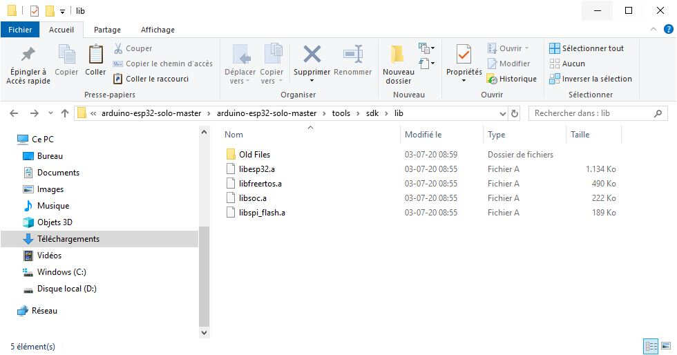
The final step of the programming was to load the code tested above on my own stuffed PCB board. Surprisingly the serial monitor sent me an error after loading the code in the ESP32-SOLO-1. The displayed message was: "E (303) cpu_start: Running on single core chip, but application is built with dual core support. ". Luckily I found an explanation in an issue tracker. Contrary to the two modules I used above to program the BLE connection, I was using a ESP32-SOLO-1 which is a single core chip. As a consequence, some files in the ESP32 libraries installed in the Arduino IDE had to be changed to make it usable for the ESP32-SOLO-1. I found the files I had to change on my computer at this location: "C:\Users\Utilisateur\AppData\Local\Arduino15\packages\esp32\hardware\esp32\1.0.4\tools\sdk". I changed them as explained in this procedure and my problem was solved.
Hereinafter you'll find the most recent version I uploaded on my ESP32-SOLO-1:
#include <BLEDevice.h>
#include <BLEServer.h>
#include <BLEUtils.h>
#include <BLE2902.h>

BLEServer *pServer = NULL;
BLECharacteristic * pTxCharacteristic;
bool deviceConnected = false;
bool oldDeviceConnected = false;
uint8_t txValue = 0;

const int PWM_period=10000;

String message = "0";
int time1;
int time2;

int ledPin = 27;

void my_delay_us(int us)
{
  while (0 < us)
  {
    delayMicroseconds(1);
    --us;
  }
}

// See the following for generating UUIDs:
// https://www.uuidgenerator.net/

#define SERVICE_UUID           "52d1987a-22ef-4edc-b61a-0e5c6fb74c5f" // UART service UUID
#define CHARACTERISTIC_UUID_RX "52d1987a-22ef-4edc-b61a-0e5c6fb74c5f"
#define CHARACTERISTIC_UUID_TX "e38bc399-2c3b-4787-96c7-b0b0ea1b0da7"


class MySecurity : public BLESecurityCallbacks {

  uint32_t onPassKeyRequest(){
    ESP_LOGI(LOG_TAG, "PassKeyRequest");
    return 199012;
  }

  void onPassKeyNotify(uint32_t pass_key){
    ESP_LOGI(LOG_TAG, "The passkey Notify number:%d", pass_key);
  }

  bool onConfirmPIN(uint32_t pass_key){
    ESP_LOGI(LOG_TAG, "The passkey YES/NO number:%d", pass_key);
    vTaskDelay(5000);
    return true;
  }

  bool onSecurityRequest(){
    ESP_LOGI(LOG_TAG, "SecurityRequest");
    return true;
  }

  void onAuthenticationComplete(esp_ble_auth_cmpl_t cmpl){
    ESP_LOGI(LOG_TAG, "Starting BLE work!");
  }

};


class MyServerCallbacks: public BLEServerCallbacks {
    void onConnect(BLEServer* pServer) {
      deviceConnected = true;
    };

    void onDisconnect(BLEServer* pServer) {
      deviceConnected = false;
    }
};

class MyCallbacks: public BLECharacteristicCallbacks {
    void onWrite(BLECharacteristic *pCharacteristic) {
      std::string rxValue = pCharacteristic->getValue();

      if (rxValue.length() > 0) {
        Serial.println("*********");
        Serial.print("Received Value: ");
        for (int i = 0; i < rxValue.length(); i++)
          Serial.print(rxValue[i]);

        Serial.println();
        Serial.println("*********");
      }

      String temp = rxValue.c_str();
      int MESSAGE = (temp).toInt();

      if (MESSAGE>=0 && MESSAGE<=20){
        message = rxValue.c_str();
      }
      else{
        Serial.println("The value must be between 0 and 20, boundaries included.");
      }
    }
};


void setup() {
  Serial.begin(115200);

  // Create the BLE Device
  BLEDevice::init("Fountain_BLE");

  //Encryption and Security
  BLEDevice::setEncryptionLevel(ESP_BLE_SEC_ENCRYPT);

  BLEDevice::setSecurityCallbacks(new MySecurity());

  // Create the BLE Server
  pServer = BLEDevice::createServer();
  pServer->setCallbacks(new MyServerCallbacks());

  // Create the BLE Service
  BLEService *pService = pServer->createService(SERVICE_UUID);

  // Create a BLE Characteristic
  pTxCharacteristic = pService->createCharacteristic(
										CHARACTERISTIC_UUID_TX,
										BLECharacteristic::PROPERTY_NOTIFY
									);

  pTxCharacteristic->addDescriptor(new BLE2902());

  BLECharacteristic * pRxCharacteristic = pService->createCharacteristic(
											 CHARACTERISTIC_UUID_RX,
											BLECharacteristic::PROPERTY_WRITE
										);

  pRxCharacteristic->setCallbacks(new MyCallbacks());

  // Start the service
  pService->start();

  // Start advertising
  pServer->getAdvertising()->start();

  //Security
  BLESecurity *pSecurity = new BLESecurity();  // pin code 설정
  uint8_t rsp_key = ESP_BLE_ENC_KEY_MASK | ESP_BLE_ID_KEY_MASK;
  uint32_t passkey = 199012; // PASS
  uint8_t auth_option = ESP_BLE_ONLY_ACCEPT_SPECIFIED_AUTH_DISABLE;
  esp_ble_gap_set_security_param(ESP_BLE_SM_SET_STATIC_PASSKEY, &passkey, sizeof(uint32_t));
  pSecurity->setAuthenticationMode(ESP_LE_AUTH_REQ_SC_MITM_BOND);
  pSecurity->setCapability(ESP_IO_CAP_OUT);
  pSecurity->setKeySize(16);
  esp_ble_gap_set_security_param(ESP_BLE_SM_ONLY_ACCEPT_SPECIFIED_SEC_AUTH, &auth_option, sizeof(uint8_t));
  pSecurity->setInitEncryptionKey(ESP_BLE_ENC_KEY_MASK | ESP_BLE_ID_KEY_MASK);
  esp_ble_gap_set_security_param(ESP_BLE_SM_SET_RSP_KEY, &rsp_key, sizeof(uint8_t));

  Serial.println("Waiting a client connection to notify...");

  pinMode(ledPin, OUTPUT);
}

void loop() {

    if (deviceConnected) {
        pTxCharacteristic->setValue(&txValue, 1);
        pTxCharacteristic->notify();
        txValue++;
		delay(10); // bluetooth stack will go into congestion, if too many packets are sent
	  }

    // disconnecting
    if (!deviceConnected && oldDeviceConnected) {
        delay(500); // give the bluetooth stack the chance to get things ready
        pServer->startAdvertising(); // restart advertising
        Serial.println("start advertising");
        oldDeviceConnected = deviceConnected;

        message="0";
    }
    // connecting
    if (deviceConnected && !oldDeviceConnected) {
		// do stuff here on connecting
        oldDeviceConnected = deviceConnected;

        message="0";
    }

    int MESSAGE = (message).toInt();

    if (MESSAGE>=0 && MESSAGE<=20){
      time1 = (MESSAGE*PWM_period)/20;
      time2 = PWM_period-time1;
    }

    digitalWrite(ledPin, HIGH);
    my_delay_us(time1);
    digitalWrite(ledPin, LOW);
    my_delay_us(time2);
}
In this code I updated the UUID with respect to the one used in the section about GUI interface programming by using a Online UUID Generator.
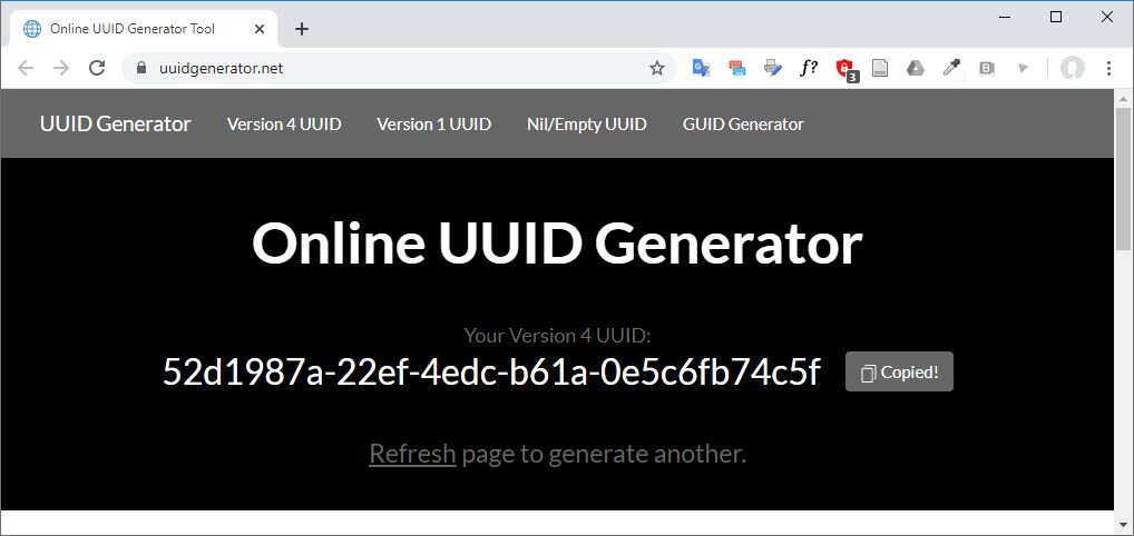
Generation of new UUIDs
GUI Programming - Javascript and Bluetooth
For the graphical user interface my first requirement was to be able to connect my computer to the Bluetooth device through the BLE protocol. The interface would consist in one or more buttons allowing the connection to the device, a slider to modify the flowrate that would be enabled only when the device would be connected and a display to know the actual value of the flowrate and be sure that the commands were actually performed. Optionally and if I had enough time I would add a frame in which the 3D model of the fountain would be displayed.
To do that I found this tutorial that explains very well how to make benefit of the Web Bluetooth API. I started the programming of the GUI with the most simple example I found on the web, a Web Bluetooth / Device Info Sample. At the beginning I found it more suitable to separate the JavaScript from the HTML but you will see later that I no longer separated them. Hereinafter is the HTML code.
<!DOCTYPE html>
<html lang="en" dir="ltr">
  <head>
    <meta charset="utf-8">
    <title>My Fountain App</title>
  </head>
  <body>
    <button onclick="myFunction()">Get Bluetooth Device</button>
    <p id="device_status">No device connected.</p>
  </body>
  <script src="bluetooth_LE.js" type="text/javascript"></script>
</html>
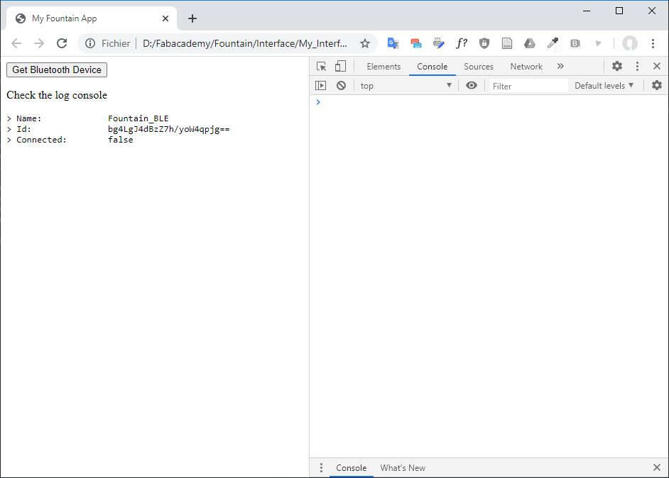
And here is the JavaScript making a Bluetooth request and writing the name, id and status (connected or not) of the device in the web browser console (press F12 to open the console in your web browser).
function myFunction() {
  document.getElementById("device_status").innerHTML = "Check the log console";

  navigator.bluetooth.requestDevice({
    acceptAllDevices: true,
    optionalServices: ['battery_service']
  })
  .then(device => {
    console.log('> Name:             ' + device.name);
    console.log('> Id:               ' + device.id);
    console.log('> Connected:        ' + device.gatt.connected);
  })
  .catch(error => { console.log(error); });
}
At the beginning the interface looks like this.
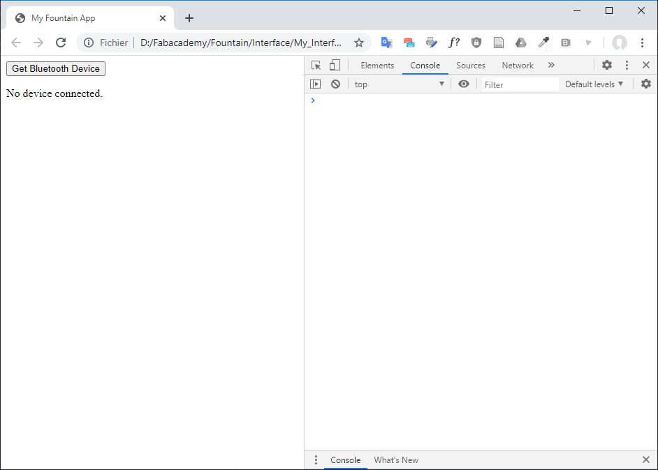
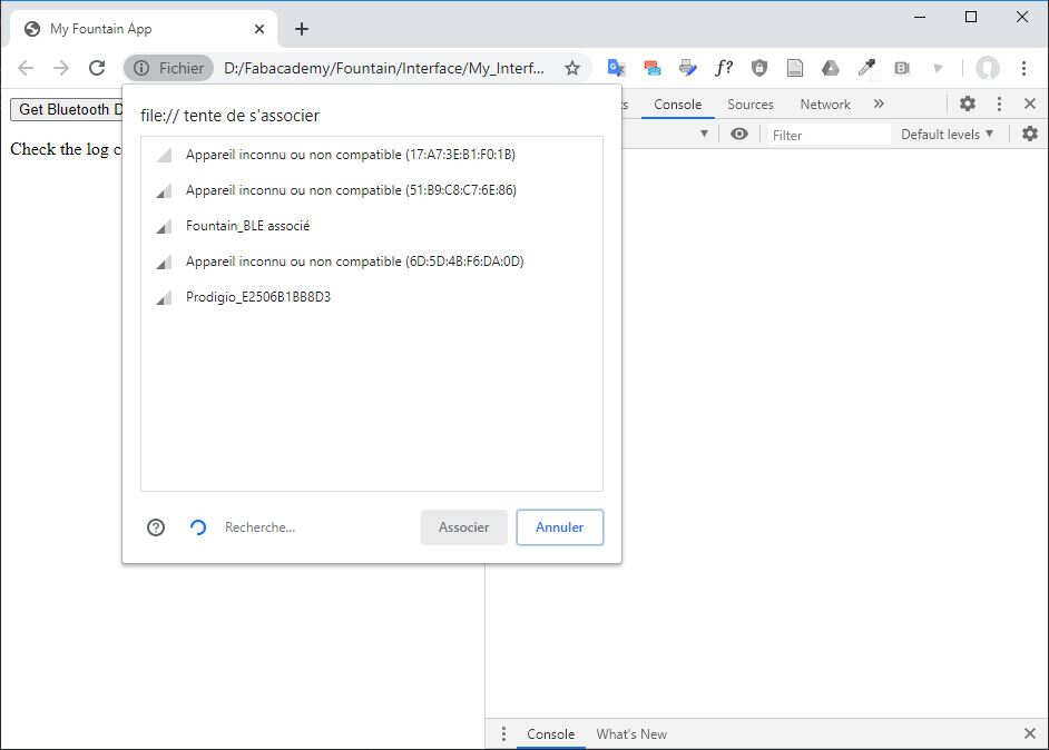
By clicking the Get Bluetooth Device a window popped up and I selected the device Fountain_BLE.
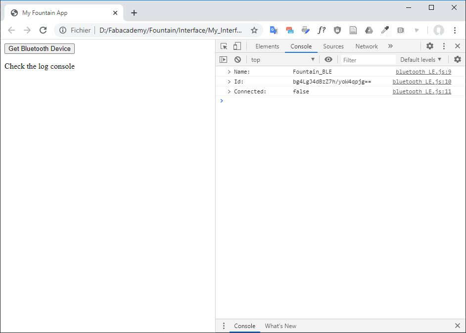
Afterwards the device characteristics can be read in the console.
Based on this example I changed the HTML file to be able to see the logs directly on the webpage.
<!DOCTYPE html>
<html lang="en" dir="ltr">
  <head>
    <meta charset="utf-8">
    <title>My Fountain App</title>
  </head>
  <body>
    <button onclick="myFunction()">Get Bluetooth Device</button>
    <p id="device_status">No device connected.</p>

    <div id="output" class="output">
      <div id="content"></div>
      <div id="status"></div>
      <pre id="log"></pre>
    </div>

  </body>
  <script src="bluetooth_LE.js" type="text/javascript"></script>

  <script>
    var ChromeSamples = {
      log: function() {
        var line = Array.prototype.slice.call(arguments).map(function(argument) {
          return typeof argument === 'string' ? argument : JSON.stringify(argument);
        }).join(' ');

        document.querySelector('#log').textContent += line + '\n';
      },

      clearLog: function() {
        document.querySelector('#log').textContent = '';
      },

      setStatus: function(status) {
        document.querySelector('#status').textContent = status;
      },

      setContent: function(newContent) {
        var content = document.querySelector('#content');
        while(content.hasChildNodes()) {
          content.removeChild(content.lastChild);
        }
        content.appendChild(newContent);
      }
    };
  </script>

  <script>
    log = ChromeSamples.log;

    function isWebBluetoothEnabled() {
      if (navigator.bluetooth) {
        return true;
      } else {
        ChromeSamples.setStatus('Web Bluetooth API is not available.\n' +
            'Please make sure the "Experimental Web Platform features" flag is enabled.');
        return false;
      }
    }
  </script>

</html>
And I adapted the JavaScript (console.log -> log).
function myFunction() {
  document.getElementById("device_status").innerHTML = "Check the log console";

  navigator.bluetooth.requestDevice({
    acceptAllDevices: true,
    optionalServices: ['battery_service']
  })
  .then(device => {
    log('> Name:             ' + device.name);
    log('> Id:               ' + device.id);
    log('> Connected:        ' + device.gatt.connected);
  })
  .catch(error => { console.log(error); });
}
The following picture presents the result.
Then I added code block in the header to a message if the Web Bluetooth API is not available on the user web browser (such as Mozilla Firefox).
<script>
      // Add a global error event listener early on in the page load, to help ensure that browsers
      // which don't support specific functionality still end up displaying a meaningful message.
      window.addEventListener('error', function(error) {
        if (ChromeSamples && ChromeSamples.setStatus) {
          console.error(error);
          ChromeSamples.setStatus(error.message + ' (Your browser may not support this feature.)');
          error.preventDefault();
        }
      });
    </script>
Finally I completely changed my strategy and I used to different examples I merged together: the Web Bluetooth / Device Disconnect Sample and the Web Bluetooth / Write Descriptor Sample. After many changes I finally got this code:
<!DOCTYPE html>
<!-- saved from url=(0075)https://googlechrome.github.io/samples/web-bluetooth/device-disconnect.html -->
<html lang="en">

<script>
(() => {
/**
 * This script injected by the installed three.js developer
 * tools extension.
 * https://github.com/threejs/three-devtools
 */

const $devtoolsReady = Symbol('devtoolsReady');
const $backlog = Symbol('backlog');

// The __THREE_DEVTOOLS__ target is small and light-weight, and collects
// events triggered until the devtools panel is ready, which is when
// the events are flushed.
const target = new class ThreeDevToolsTarget extends EventTarget {
  constructor() {
    super();
    this[$devtoolsReady] = false;
    this[$backlog] = [];
    this.addEventListener('devtools-ready', e => {
      this[$devtoolsReady] = true;
      for (let event of this[$backlog]) {
        this.dispatchEvent(event);
      }
    }, { once: true });
  }

  dispatchEvent(event) {
    if (this[$devtoolsReady] || event.type === 'devtools-ready') {
      super.dispatchEvent(event);
    } else {
      this[$backlog].push(event);
    }
  }
}

Object.defineProperty(window, '__THREE_DEVTOOLS__', {
  value: target,
});
})();
</script>

<head>
  <meta http-equiv="Content-Type" content="text/html; charset=UTF-8">
  <meta http-equiv="X-UA-Compatible" content="IE=edge">
  <meta name="viewport" content="width=device-width, initial-scale=1">

  <title>Web Bluetooth / Device Disconnect Sample</title>

  <script>
    // Add a global error event listener early on in the page load, to help ensure that browsers
    // which don't support specific functionality still end up displaying a meaningful message.
    window.addEventListener('error', function(error) {
      if (ChromeSamples && ChromeSamples.setStatus) {
        console.error(error);
        ChromeSamples.setStatus(error.message + ' (Your browser may not support this feature.)');
        error.preventDefault();
      }
    });
  </script>

  <link rel="icon" href="./index_files/icon.png">
  <link rel="stylesheet" href="./index_files/main.css">
</head>

<body cz-shortcut-listen="true">
  <img class="pageIcon" src="./index_files/icon.png">
  <h1>Web Bluetooth / Device Disconnect Sample</h1>
  <script>
    if('serviceWorker' in navigator) {
      navigator.serviceWorker.register('service-worker.js');
    }
  </script>
  <script>
    window.addEventListener('DOMContentLoaded', function() {
      const searchParams = new URL(location).searchParams;
      const inputs = Array.from(document.querySelectorAll('input[id]'));

      inputs.forEach(input => {
        if (searchParams.has(input.id)) {
          if (input.type == 'checkbox') {
            input.checked = searchParams.get(input.id);
          } else {
            input.value = searchParams.get(input.id);
            input.blur();
          }
        }
        if (input.type == 'checkbox') {
          input.addEventListener('change', function(event) {
            const newSearchParams = new URL(location).searchParams;
            if (event.target.checked) {
              newSearchParams.set(input.id, event.target.checked);
            } else {
              newSearchParams.delete(input.id);
            }
            history.replaceState({}, '', Array.from(newSearchParams).length ?
                location.pathname + '?' + newSearchParams : location.pathname);
          });
        } else {
          input.addEventListener('input', function(event) {
            const newSearchParams = new URL(location).searchParams;
            if (event.target.value) {
              newSearchParams.set(input.id, event.target.value);
            } else {
              newSearchParams.delete(input.id);
            }
            history.replaceState({}, '', Array.from(newSearchParams).length ?
                location.pathname + '?' + newSearchParams : location.pathname);
          });
        }
      });
    });
  </script>

  <form>
    <button id="scan">Scan</button>
    <button id="disconnect">Disconnect</button>
    <button id="reconnect">Reconnect</button>
  </form>

  <p>
    <input id="description" type="text" placeholder="Characteristic User Description">
    <button id="writeButton" disabled="">Set Characteristic User Description</button>
  </p>

  <div class="slidecontainer">
    <input type="range" min="0" max="20" value="0" class="slider" id="myRange" disabled="">
    <p>Value: <span id="myCharacteristicValue"></span></p>
  </div>

  <script>
    var ChromeSamples = {
      log: function() {
        var line = Array.prototype.slice.call(arguments).map(function(argument) {
          return typeof argument === 'string' ? argument : JSON.stringify(argument);
        }).join(' ');

        document.querySelector('#log').textContent += line + '\n';
      },

      clearLog: function() {
        document.querySelector('#log').textContent = '';
      },

      setStatus: function(status) {
        document.querySelector('#status').textContent = status;
      },

      setContent: function(newContent) {
        var content = document.querySelector('#content');
        while(content.hasChildNodes()) {
          content.removeChild(content.lastChild);
        }
        content.appendChild(newContent);
      }
    };
  </script>

  <h3>Live Output</h3>

  <div id="output" class="output">
    <div id="content"></div>
    <div id="status"></div>
    <pre id="log">Requesting Bluetooth Device...
      Argh! TypeError: Failed to execute 'requestDevice' on 'Bluetooth': 'filters' member must be non-empty to find any devices.
    </pre>
  </div>


  <script>
    if (/Chrome\/(\d+\.\d+.\d+.\d+)/.test(navigator.userAgent)){
      // Let's log a warning if the sample is not supposed to execute on this
      // version of Chrome.
      if (50 > parseInt(RegExp.$1)) {
        ChromeSamples.setStatus('Warning! Keep in mind this sample has been tested with Chrome ' + 50 + '.');
      }
    }
  </script>


<script>
var bluetoothDevice;
var myCharacteristic;

var serviceUuid = '52d1987a-22ef-4edc-b61a-0e5c6fb74c5f';
var characteristicUuid = '52d1987a-22ef-4edc-b61a-0e5c6fb74c5f';

function onScanButtonClick() {
  bluetoothDevice = null;
  log('Requesting Bluetooth Device...');
  /*
  //Accept all devices
  navigator.bluetooth.requestDevice({
      acceptAllDevices: true,
      optionalServices: [serviceUuid]
    })
  */
  //Filter on device name
  navigator.bluetooth.requestDevice({filters: [{ name: 'Fountain_BLE' }], optionalServices: [serviceUuid] })
  .then(device => {
    bluetoothDevice = device;
    bluetoothDevice.addEventListener('gattserverdisconnected', onDisconnected);
    log('Connecting to Bluetooth Device...');
    return bluetoothDevice.gatt.connect();
  })
  .then(server => {
    log('> Bluetooth Device connected');
    log('Getting Service...');
    return server.getPrimaryService(serviceUuid);
  })
  .then(service => {
    log('Getting Characteristic...');
    return service.getCharacteristic(characteristicUuid);
  })
  .then(characteristic => {
    document.querySelector('#myRange').disabled = false;
    myCharacteristic = characteristic;
    log('Proceeding...');
    onSelectRange();
  })
  .catch(error => {
    document.querySelector('#myRange').disabled = true;
    log('Argh! ' + error);
  });
}

function connect() {
  log('Connecting to Bluetooth Device...');
  return bluetoothDevice.gatt.connect()
  .then(server => {
    log('> Bluetooth Device connected');
    log('Getting Service...');
    return server.getPrimaryService(serviceUuid);
  })
  .then(service => {
    log('Getting Characteristic...');
    return service.getCharacteristic(characteristicUuid);
  })
  .then(characteristic => {
    document.querySelector('#myRange').disabled = false;
    myCharacteristic = characteristic;
    log('Proceeding...');
  });
}

function onDisconnectButtonClick() {
  if (!bluetoothDevice) {
    return;
  }
  log('Disconnecting from Bluetooth Device...');
  if (bluetoothDevice.gatt.connected) {
    bluetoothDevice.gatt.disconnect();
  } else {
    log('> Bluetooth Device is already disconnected');
  }
}

function onDisconnected(event) {
  // Object event.target is Bluetooth Device getting disconnected.
  document.querySelector('#myRange').disabled = true;
  log('> Bluetooth Device disconnected');
}

function onReconnectButtonClick() {
  if (!bluetoothDevice) {
    return;
  }
  if (bluetoothDevice.gatt.connected) {
    log('> Bluetooth Device is already connected');
    return;
  }
  connect()
  .catch(error => {
    log('Argh! ' + error);
  });
}

function onSelectRange() {
  if (!myCharacteristic) {
    return;
  }
  let encoder = new TextEncoder('utf-8');
  let value = document.querySelector('#myRange').value;
  var output = document.getElementById("myCharacteristicValue");
  log('Setting Characteristic value...');
  myCharacteristic.writeValue(encoder.encode(value))
  .then(_ => {
    log('> Characteristic changed to: ' + value);
    output.innerHTML = value;
  })
  .catch(error => {
    log('Argh! ' + error);
  });
}
</script>

<script>
  document.querySelector('#scan').addEventListener('click', function(event) {
    event.stopPropagation();
    event.preventDefault();

    if (isWebBluetoothEnabled()) {
      ChromeSamples.clearLog();
      onScanButtonClick();
    }
  });
  document.querySelector('#disconnect').addEventListener('click', function(event) {
    event.stopPropagation();
    event.preventDefault();

    if (isWebBluetoothEnabled()) {
      ChromeSamples.clearLog();
      onDisconnectButtonClick();
    }
  });
  document.querySelector('#reconnect').addEventListener('click', function(event) {
    event.stopPropagation();
    event.preventDefault();

    if (isWebBluetoothEnabled()) {
      ChromeSamples.clearLog();
      onReconnectButtonClick();
    }
  });
  document.querySelector('#myRange').addEventListener('click', function() {
    onSelectRange();
  });
</script>

<script>
  log = ChromeSamples.log;

  function isWebBluetoothEnabled() {
    if (navigator.bluetooth) {
      return true;
    } else {
      ChromeSamples.setStatus('Web Bluetooth API is not available.\n' +
          'Please make sure the "Experimental Web Platform features" flag is enabled.');
      return false;
    }
  }
</script>

<script>
  /* jshint ignore:start */
  (function(i,s,o,g,r,a,m){i['GoogleAnalyticsObject']=r;i[r]=i[r]||function(){
      (i[r].q=i[r].q||[]).push(arguments)},i[r].l=1*new Date();a=s.createElement(o),
    m=s.getElementsByTagName(o)[0];a.async=1;a.src=g;m.parentNode.insertBefore(a,m)
  })(window,document,'script','https://www.google-analytics.com/analytics.js','ga');
  ga('create', 'UA-53563471-1', 'auto');
  ga('send', 'pageview');
  /* jshint ignore:end */
</script>

</body>
</html>
To change the characteristic value I found this code line very valuable:
console.log(typeof slider.value);Thanks to the command typeof, it returned the type of the variable given by the range slider, in this case, a string.
Learning about the addEventListener() Method was also a plus to debug the code.
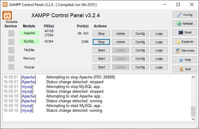
The last step of my GUI programming was about the layout. I added some CSS files and I decided to add the three.js OBJ + MTL Loader. More information can be found about this topic on the page dedicated to Interface and Application Programming. Thanks to XAMPP I emulated the behavior of Apache and MySQL services on the localhost.
I ended up with the application as shown in the following picture.
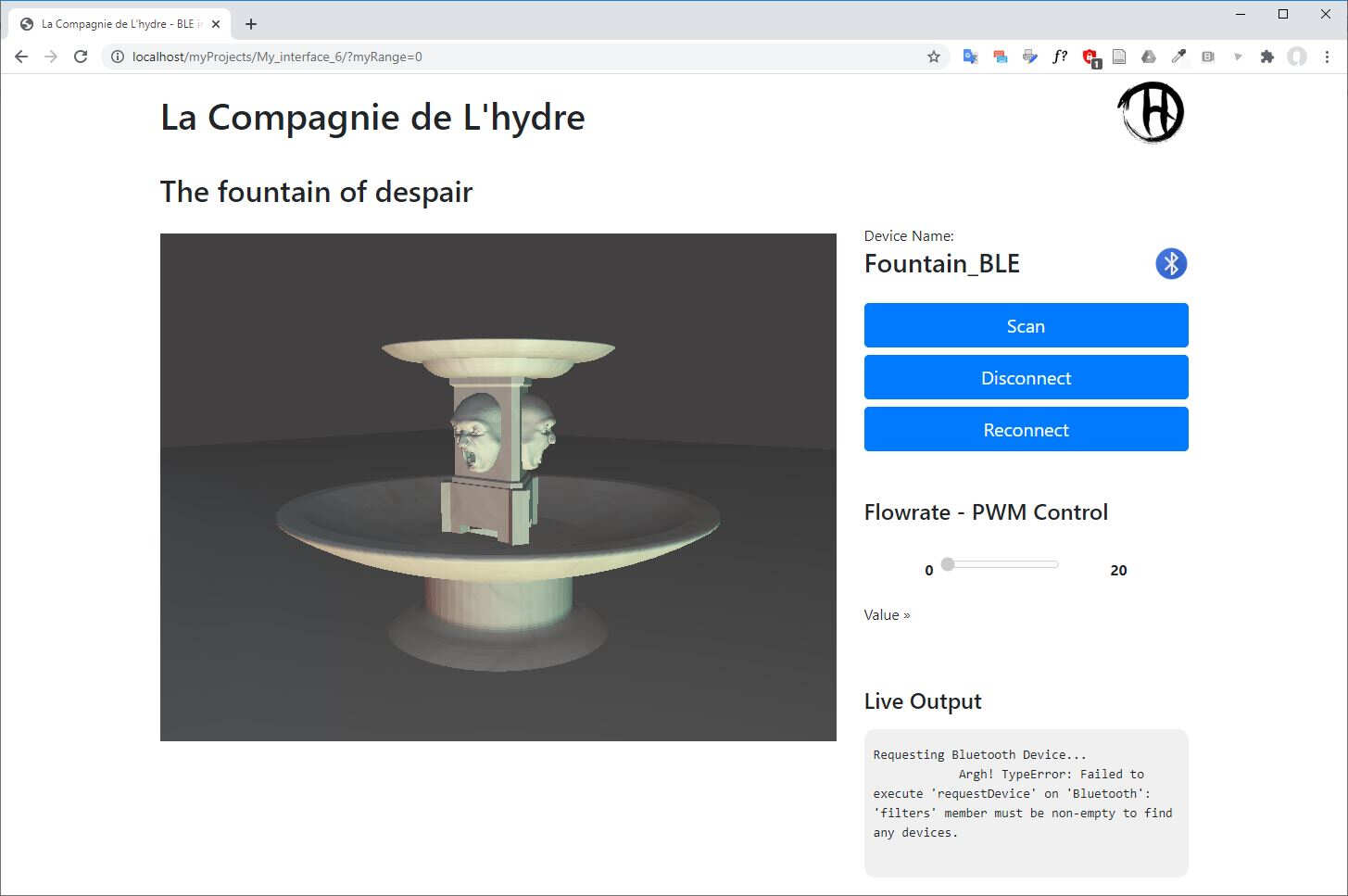
The following video shows the ability to view the 3D model. Here is the reference for the three.js - OBJ and MTL loader.
GUI with three.js - OBJ and MTL loader
This video shows the pairing of the Bluetooth device with the computer
Pairing of the BLE device with the computer
And the last one shows the scan of the device with the application.
Scan of the device with the application
If you are interested in the use of the application to control the waterflow, skip the Fabrication section and see directly the Results. The files of this application are available here. You can also try the application here.
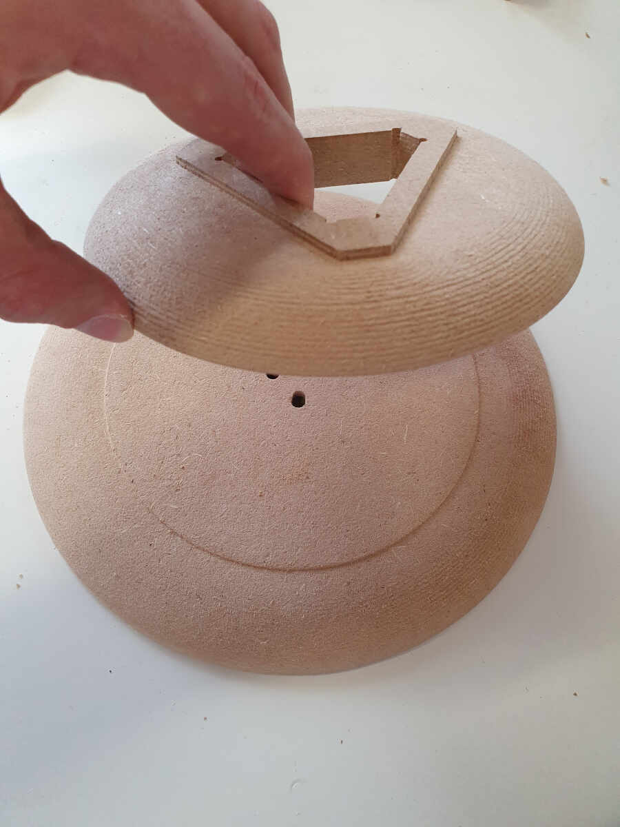
Fabrication
In this section I'll explain all the different fabrication steps be it the 3D printing, the CNC cutting, the assembly, the molding and casting and the finishes.
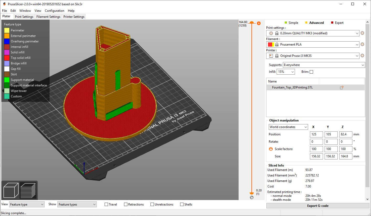
3D printing
For the 3D I imported the STL files in PrusaSlicer.
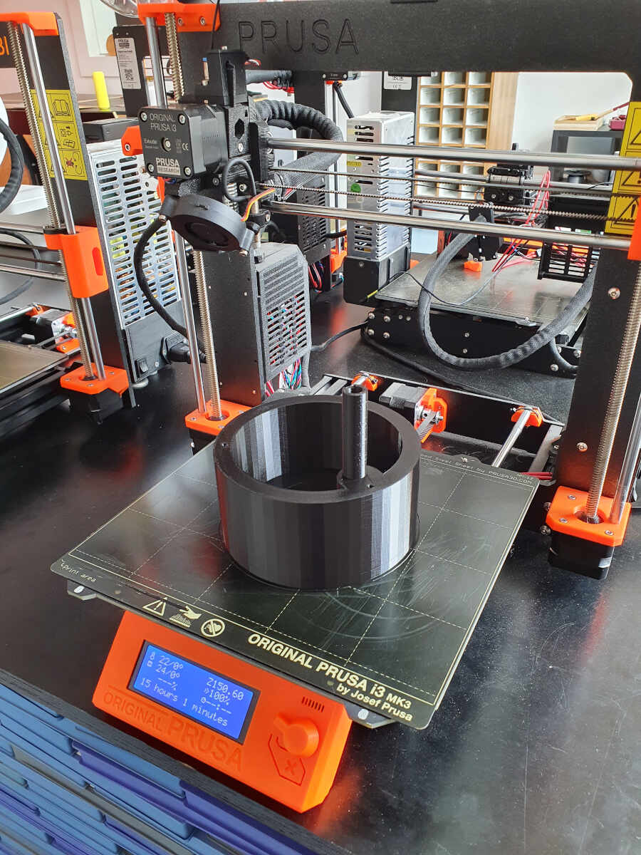
The following video shows the printers in action.
3D printing of the water container
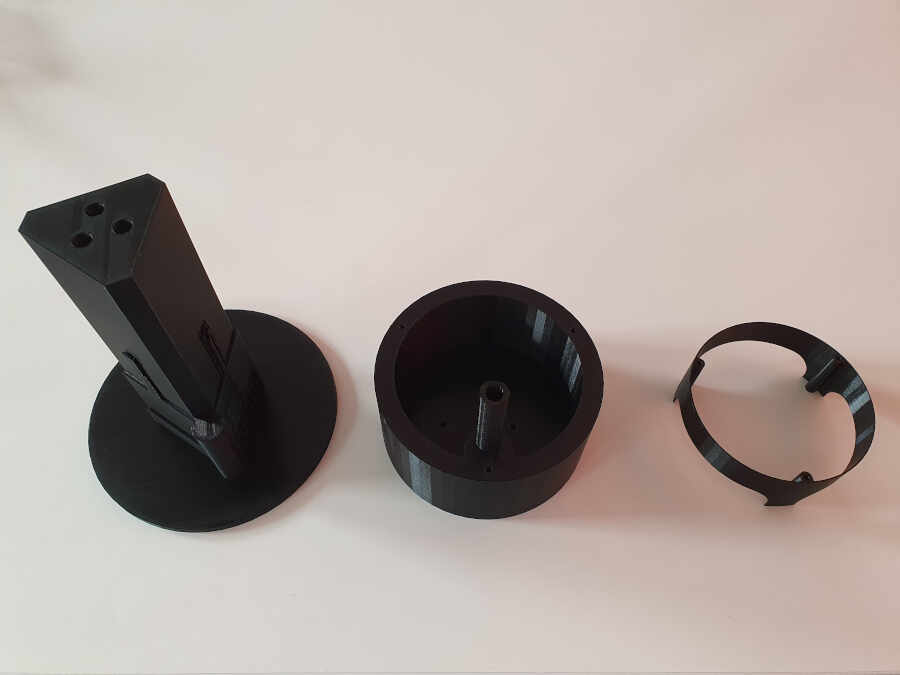
Here is the top part of the fountain, the water dispenser.
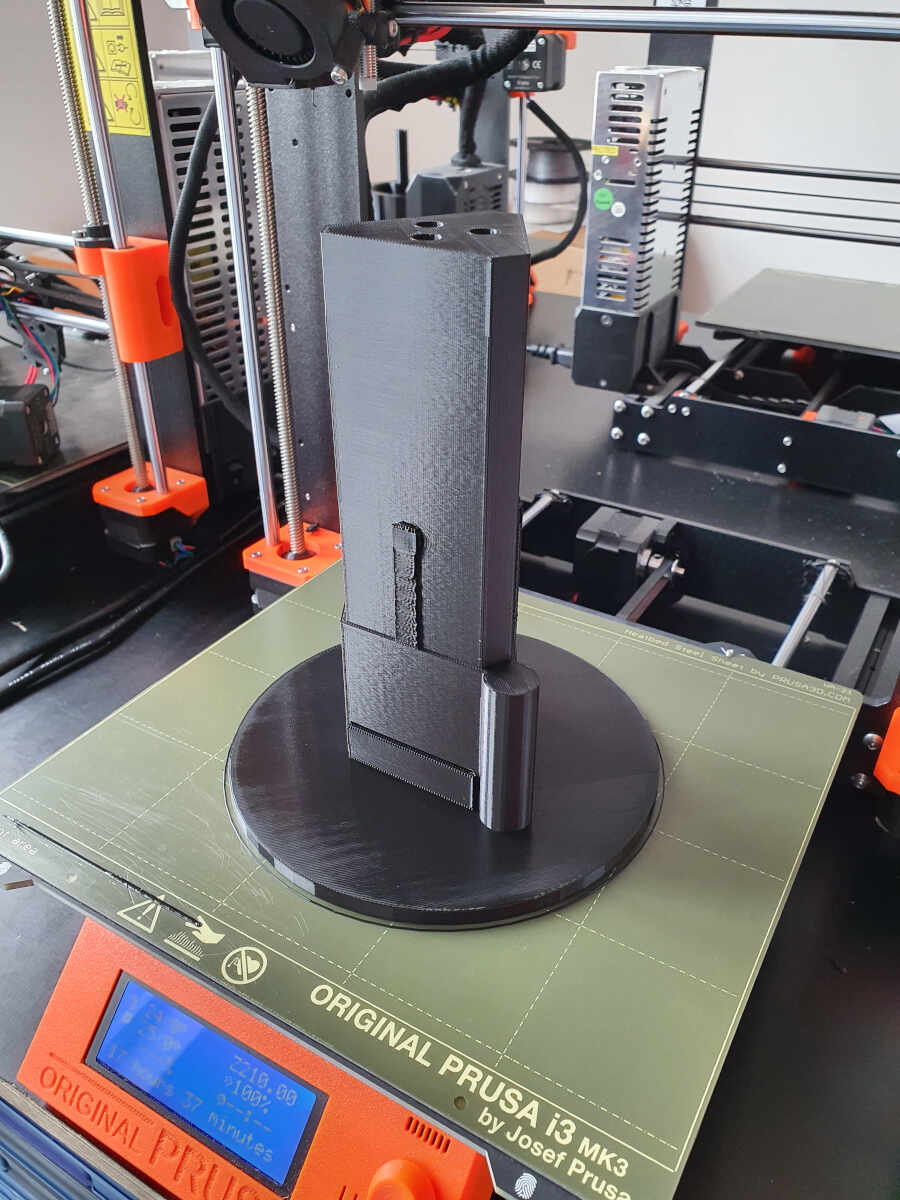
Here is the water tank of the fountain.
The third part on the right is the electronics spacer/enclosure.
Right after I tested the water dispenser and it worked really well.
Testing of the water flow
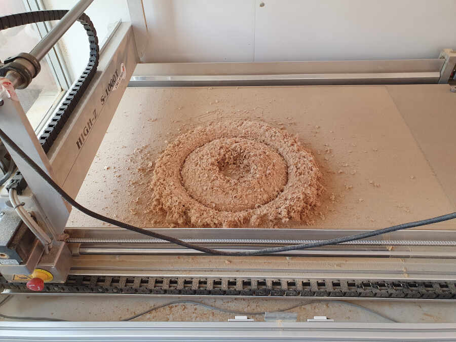
CNC cutting
To cut the MDF parts with the CNC cutter I prepared the files within SolidWorks with HMSWorks, the SolidWorks plug-in developed by Autodesk that adds a new CAM tab in SolidWorks. I prepared the files similarly to the ones prepared during the week about computer-controlled machining.
Machining the MDF parts
The following picture shows how I fixed the stock rigidly on the machine bed.
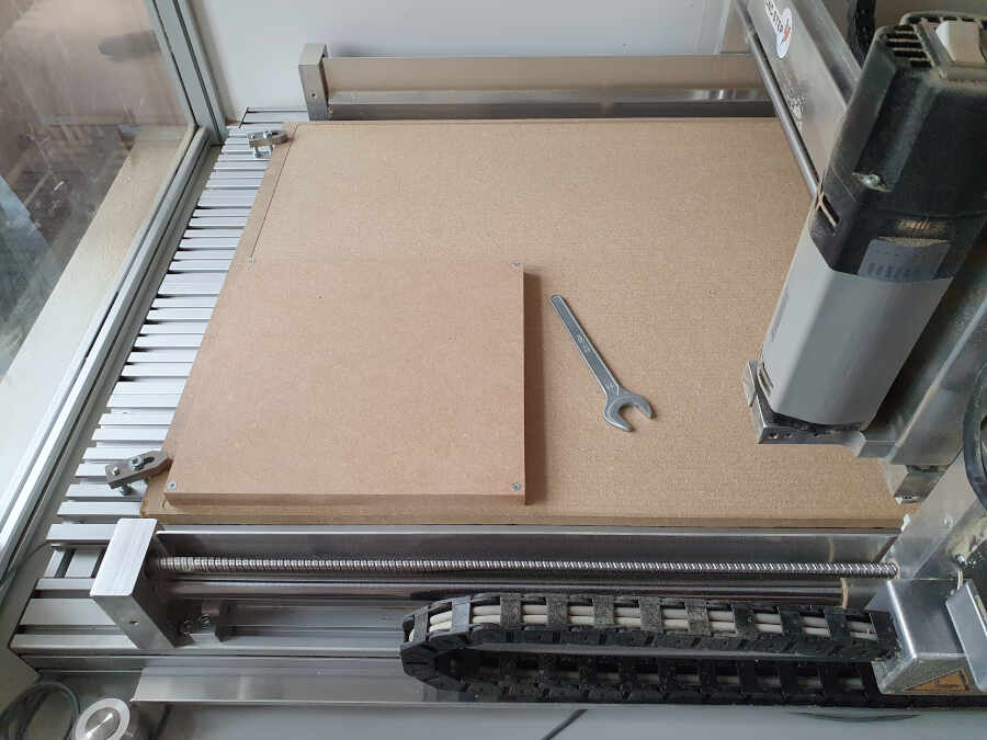
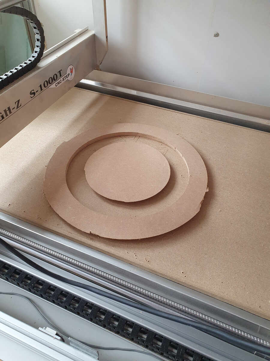
Here is the result when the machine finished one job.
And there are two parts that needed to be milled on both up and down sides. To do it I just flipped the parts and followed the technics I already used and explained during the week about composites when I had done a wind turbine blade.
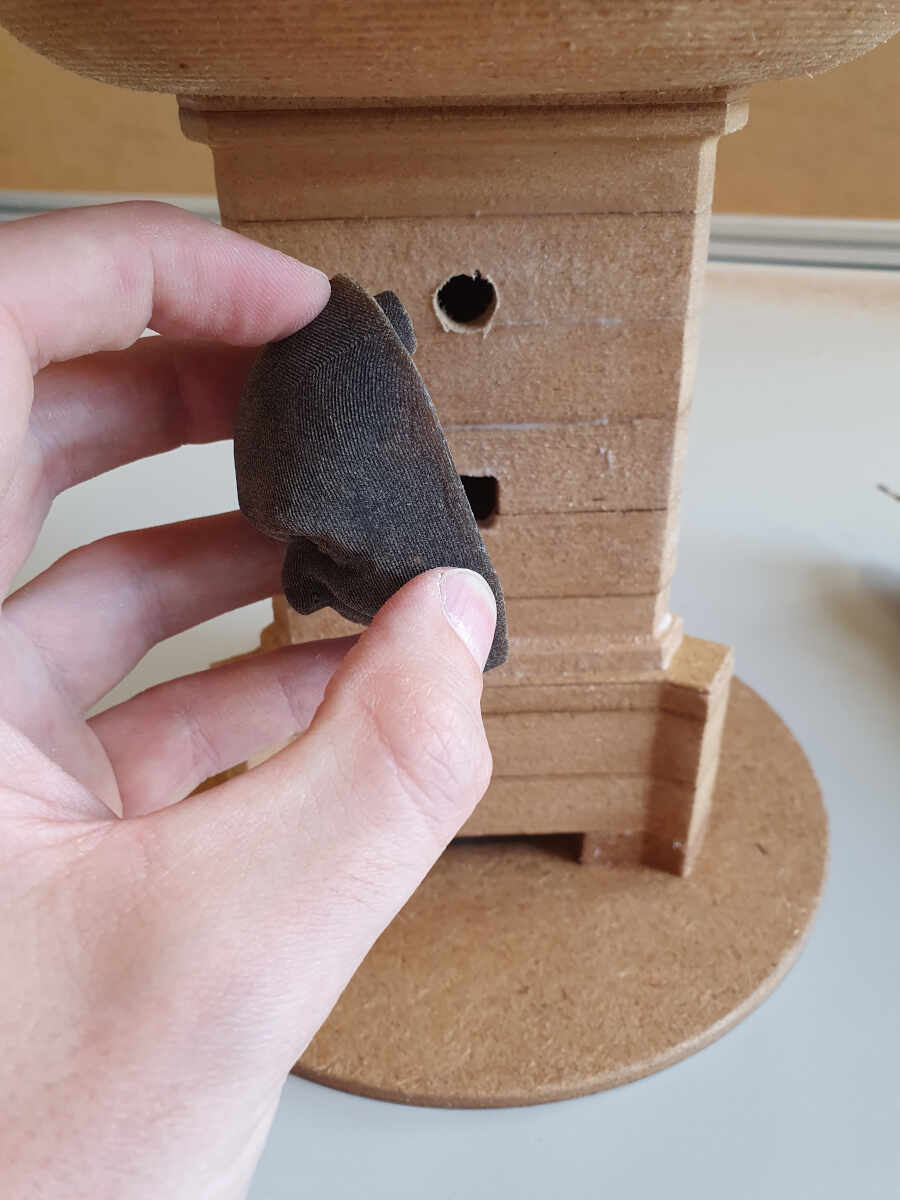
Testing the waterproofing technics
I used a broken part of mine as a test part to validate the method used to waterproof the fountain. It is well known that MDF is a materials that absorbs quickly a lot of liquids and that it expands while doing it.
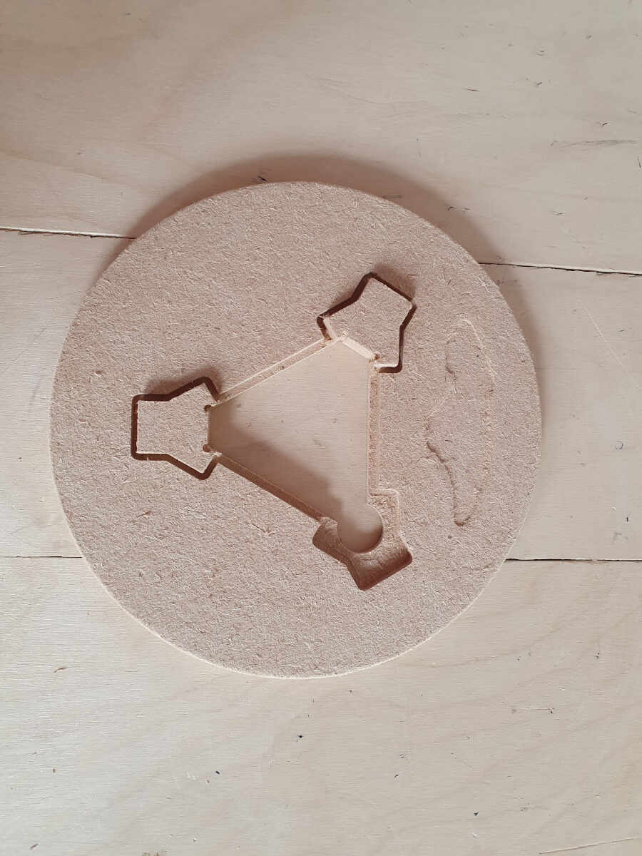
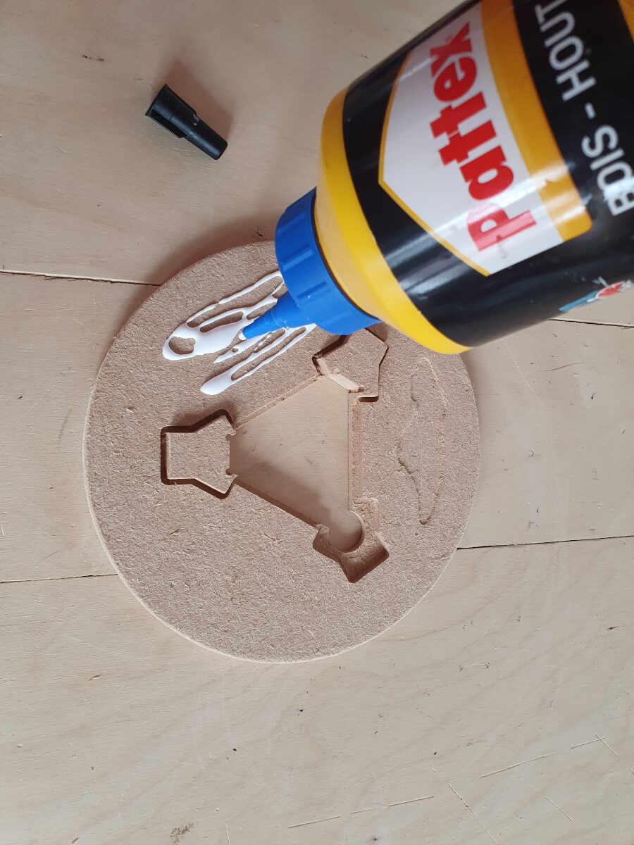
A technic known from painters is to put a thin layer of wood glue on the MDF and let it dry before applying varnish.
In my case, I would not apply a varnish.
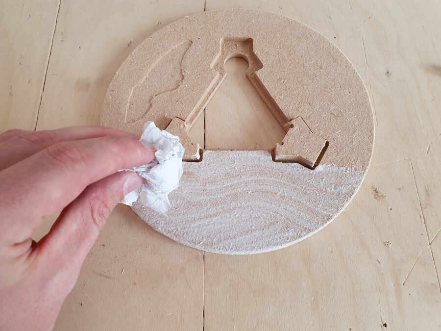
I applied polyurethane on two thirds of the testing part: one third where the wood glue was applied and one third directly on the MDF leaving the last third untouched.
As the following picture shows, the part where the wood glue was first applied has a much nicer aspect and the no water was able to pierce it.
Assembly of the MDF with the plastic parts
The following video shows how I assembled the different parts together.
Assembling of the MDF parts with the 3D printed parts
To center the larger MDF parts of the fountain cavity together I temporarily put the water dispenser in front of the water tank.
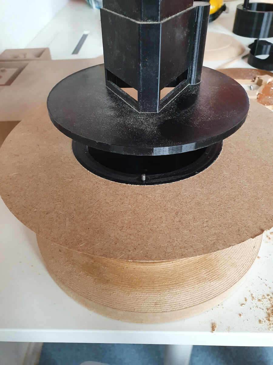
Afterwards I screwed the plastic parts of the fountain dispenser...
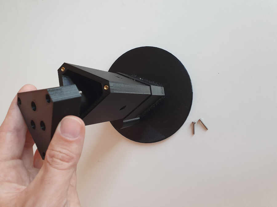
and I glued the upper parts of the fountain together.
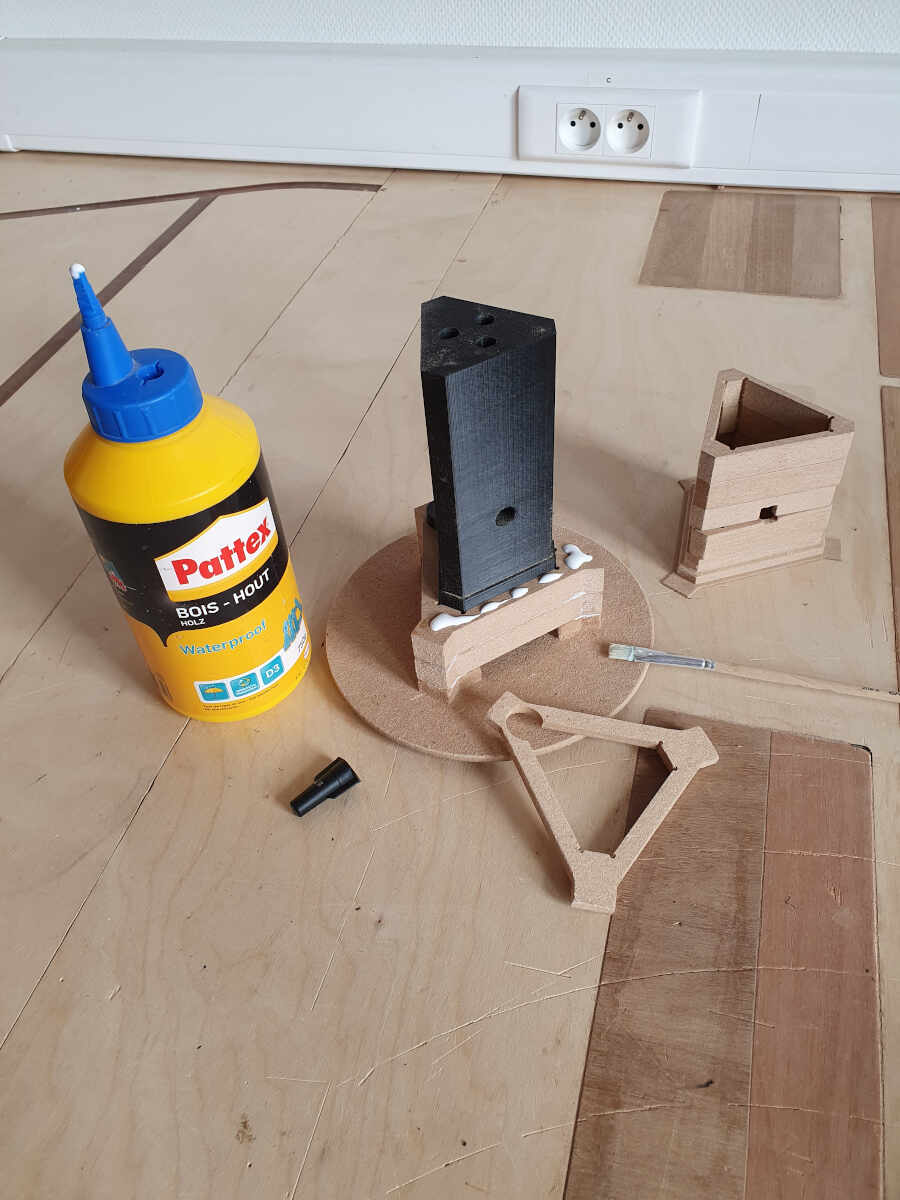
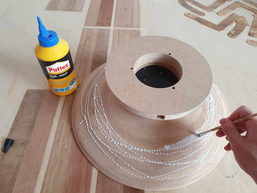
Then I applied a thin layer of wood glue allover the fountain.
Laser cutting
To enclose the electronics without hiding it too much (because I think it is beautiful) I lasered cut a Plexiglas window on the EpilogLaserCutter.
Cutting the window of the electronics box with the laser cutter
To be sure that the water would not pierce the fountain cavity trough the screw threads, I laser cut a rubber seal.
Cutting the rubber seal with the laser cutter
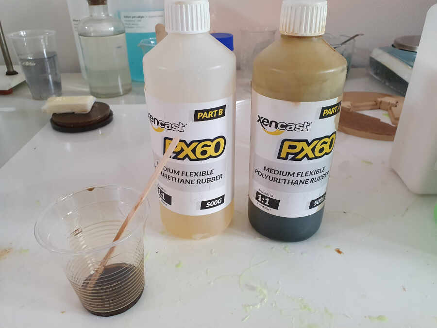
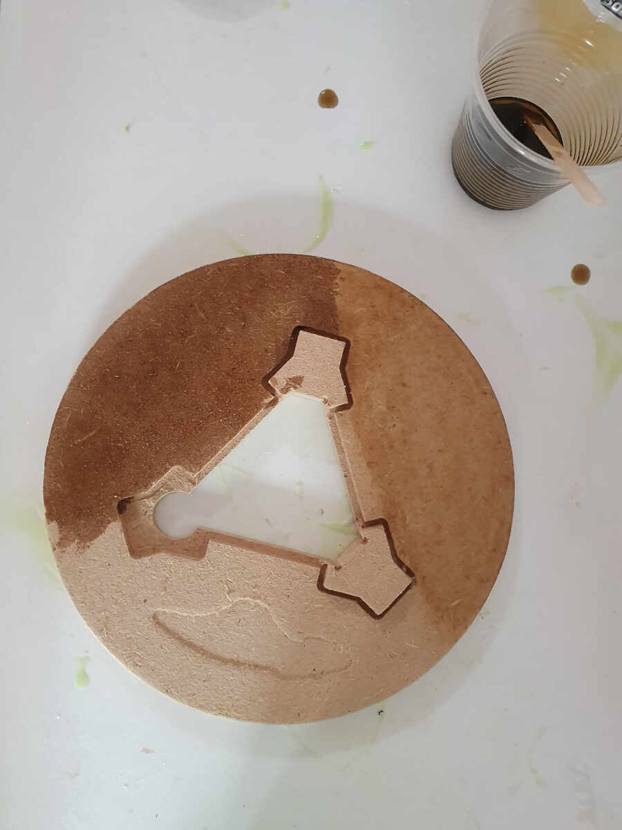
Molding and casting
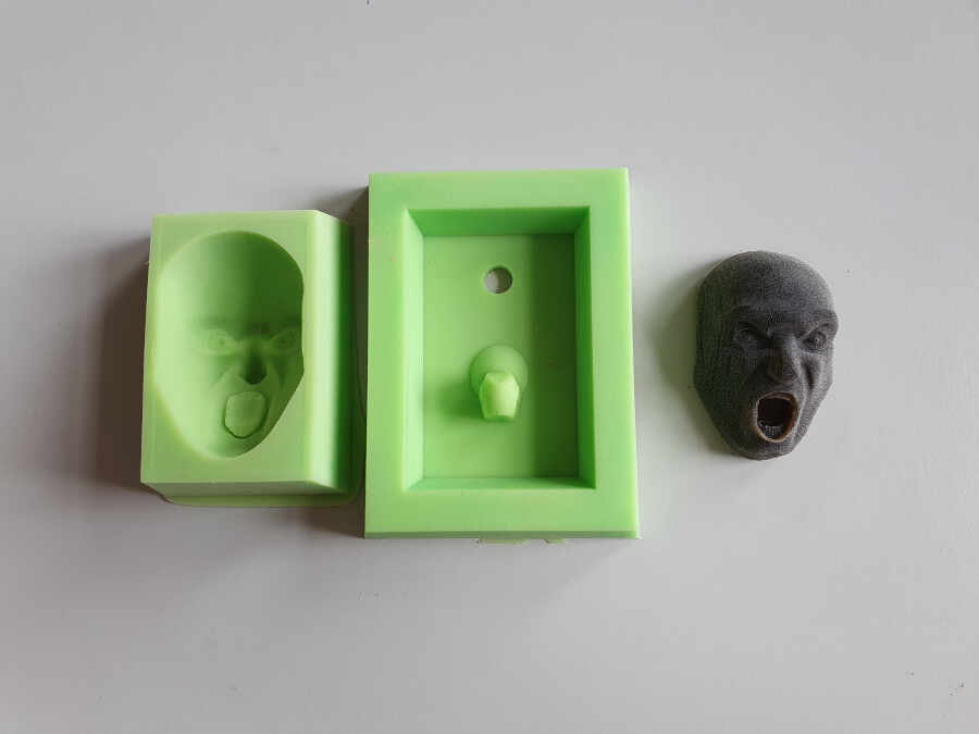
To make the heads I first made two positive molds from which I casted two negative silicone molds.
Casting the mold with polyurethane
The following pictures show one head casted from the silicone molds. The heads are made of polyurethane, the same materials I used to make the fountain waterproof. The procedure to create the molds is described in detail on the page dedicated to the week about Molding and casting.
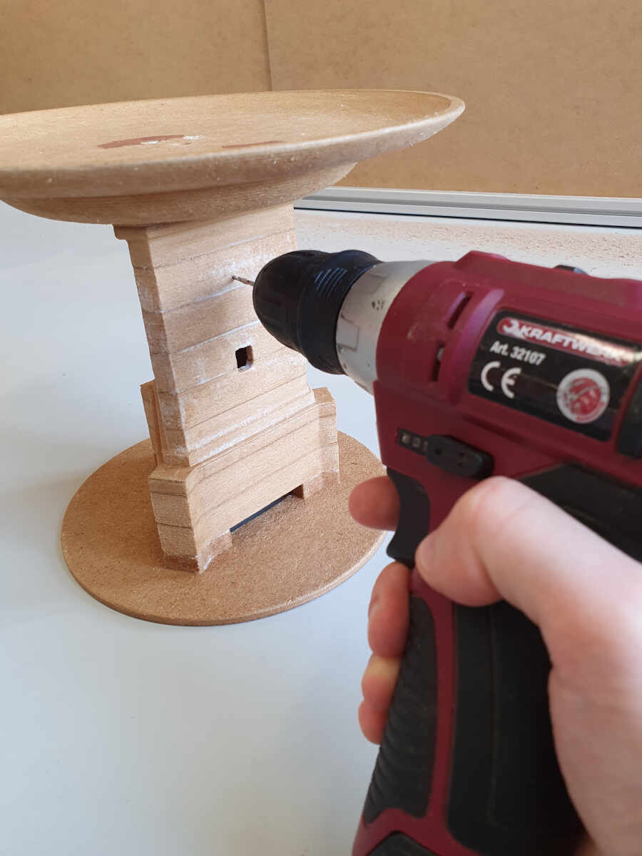
To precisely fix the heads on the fountain top I manually made a 10mm ϕ hole in the top of the fountain.
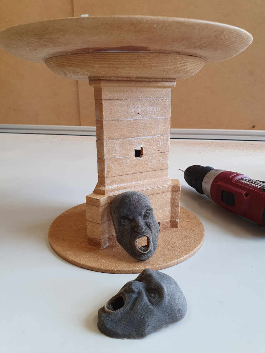
But before pasting the heads on the fountain top I first applied a layer of polyurethane everywhere on the top and I glued the heads on the fountain with the same material.
Painting
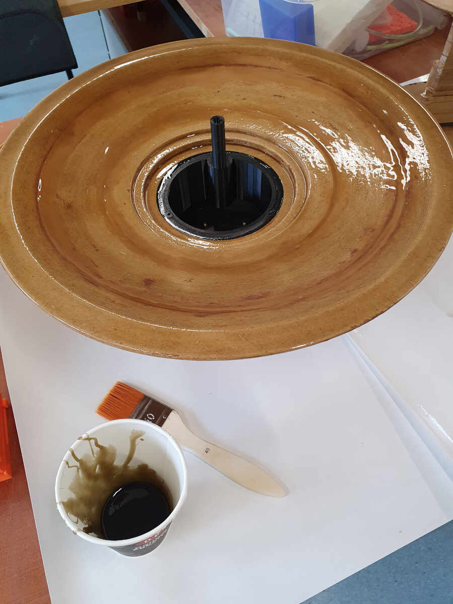
To finish the fountain I painted it with a mix of white, black, red and yellow acrylic painting. The solvent of acrylic painting is water but once it is dry it leaves a thin layer of plastic which makes the painting waterproof.
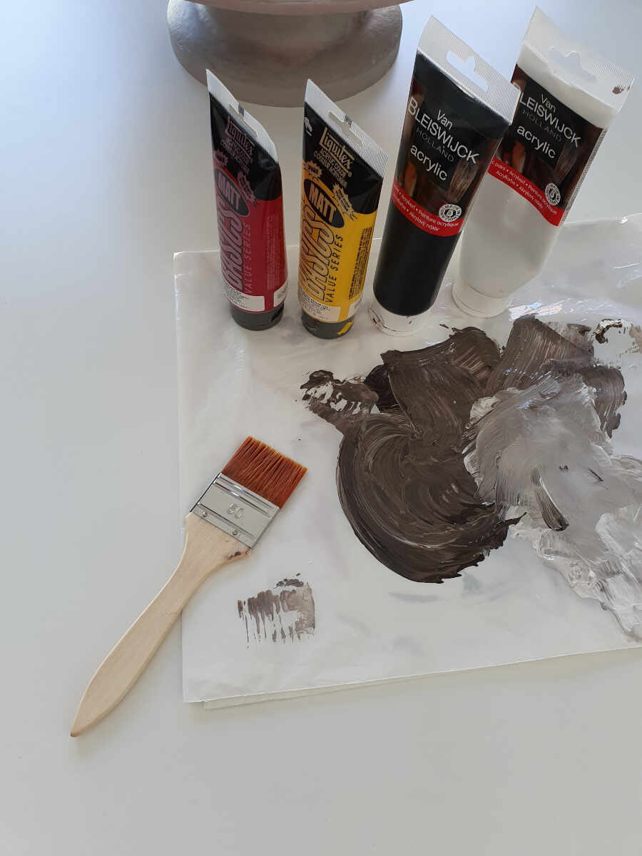
To mix the painting feel free to experiment. I personally preferred to put a lot of white painting. Then to apply it I gently tapped the painting with a brush as shown in the video. It allows to blend the painting.
Painting the fountain with acrylic
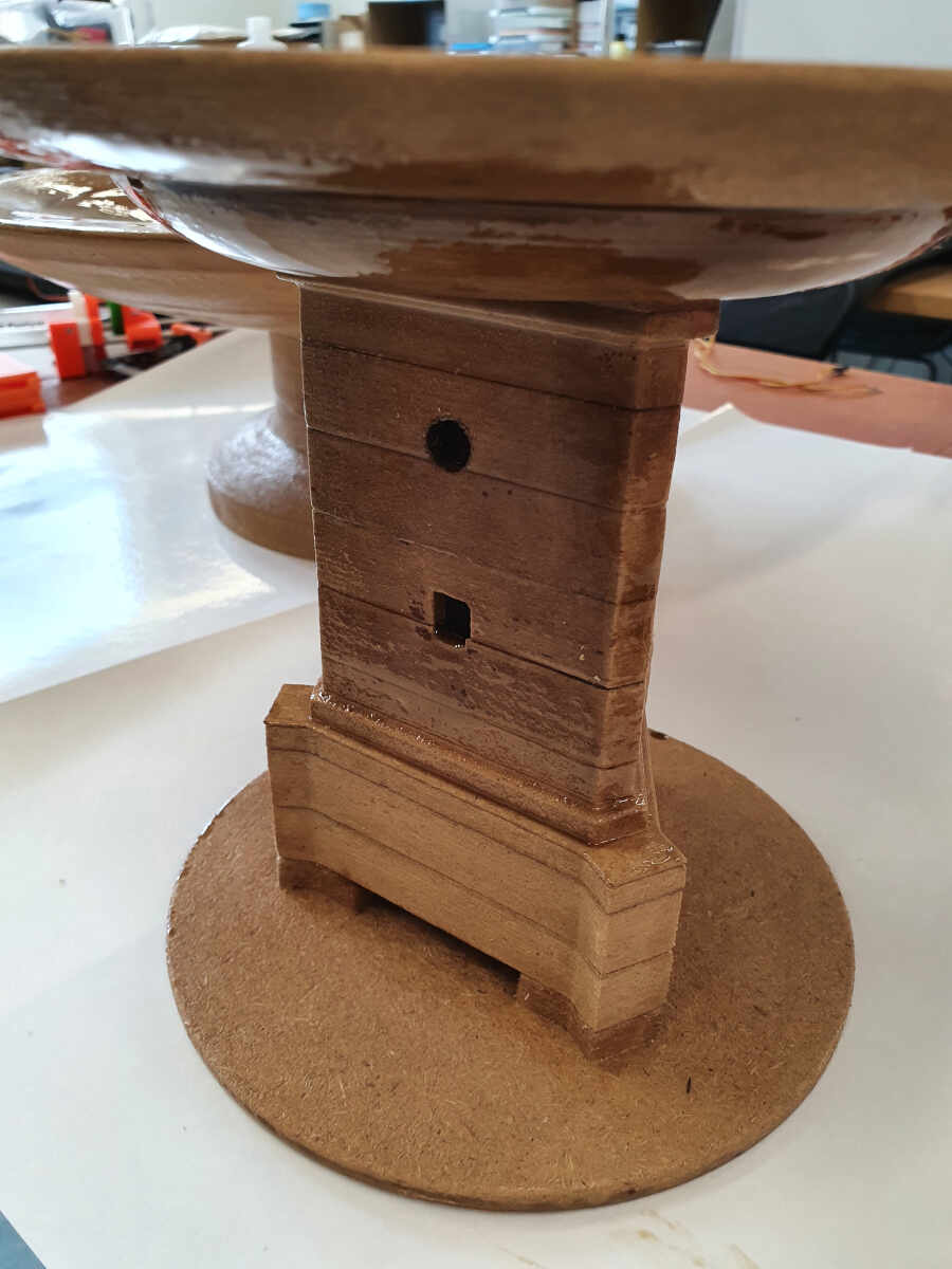
After three layers of painting, here is the result.
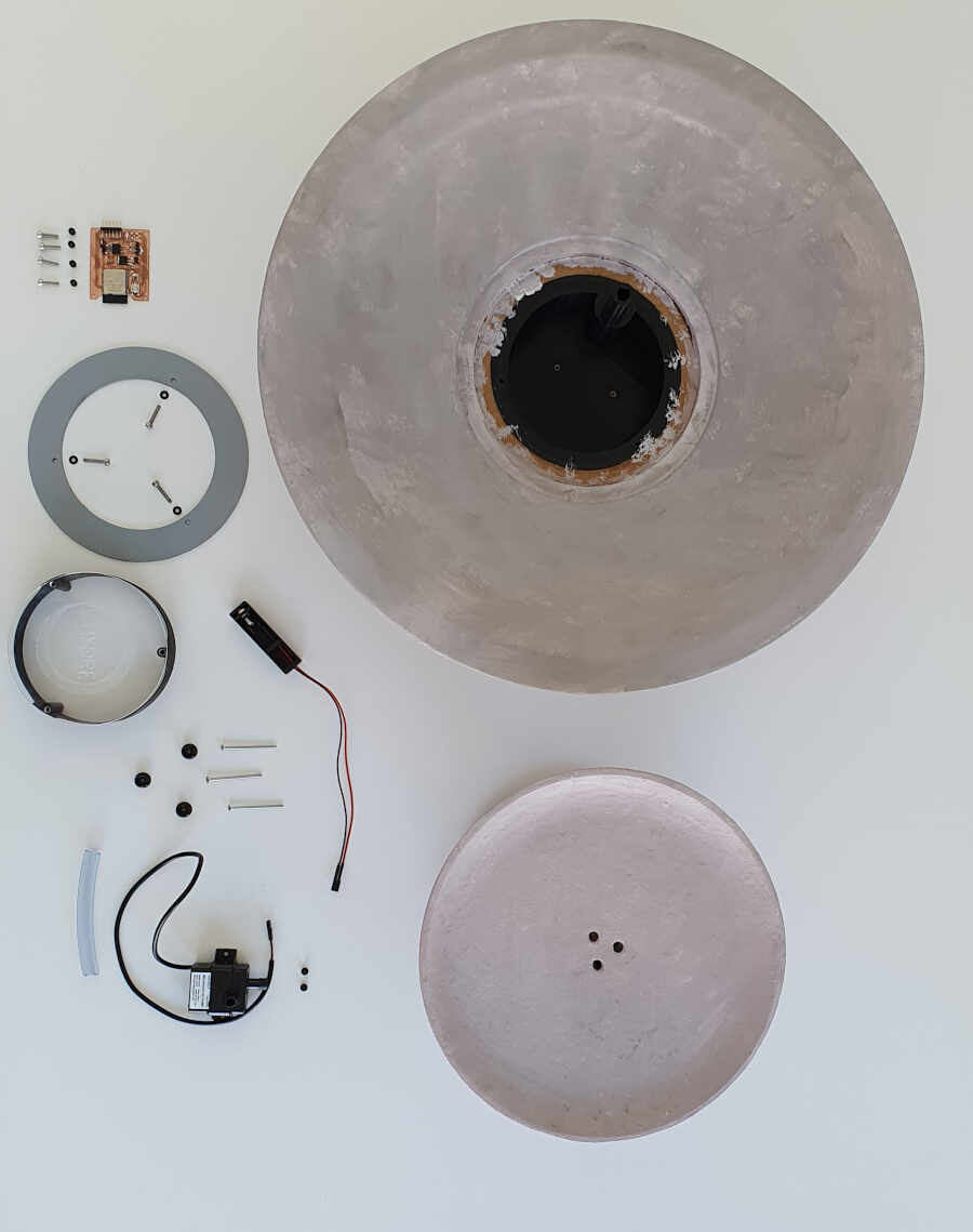
Final assembly
In this section all parts are finished, they just need to be assembled.
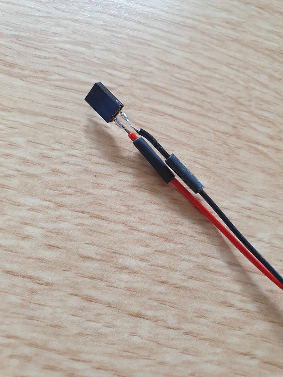
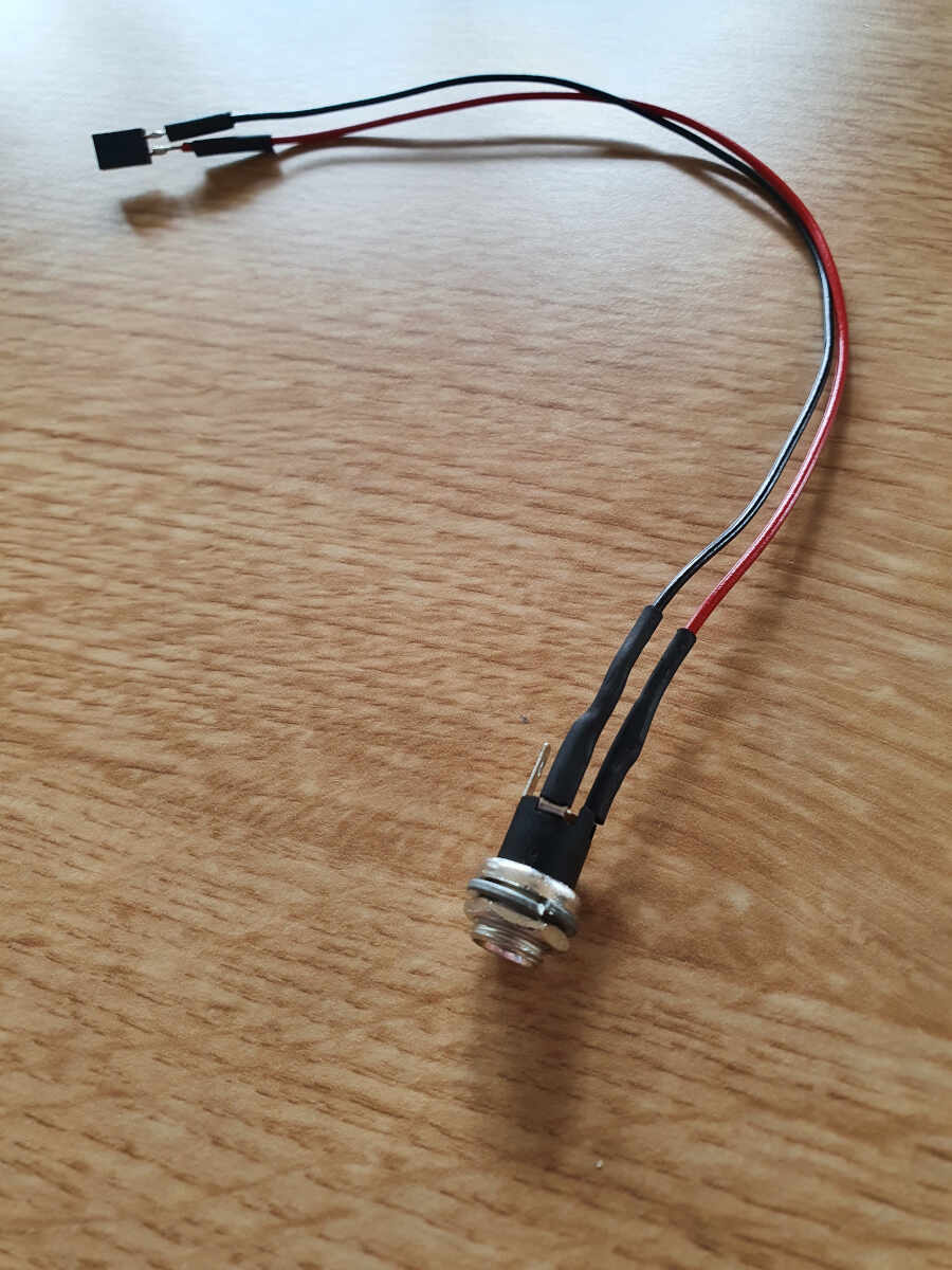
I soldered the wires to the jack socket.
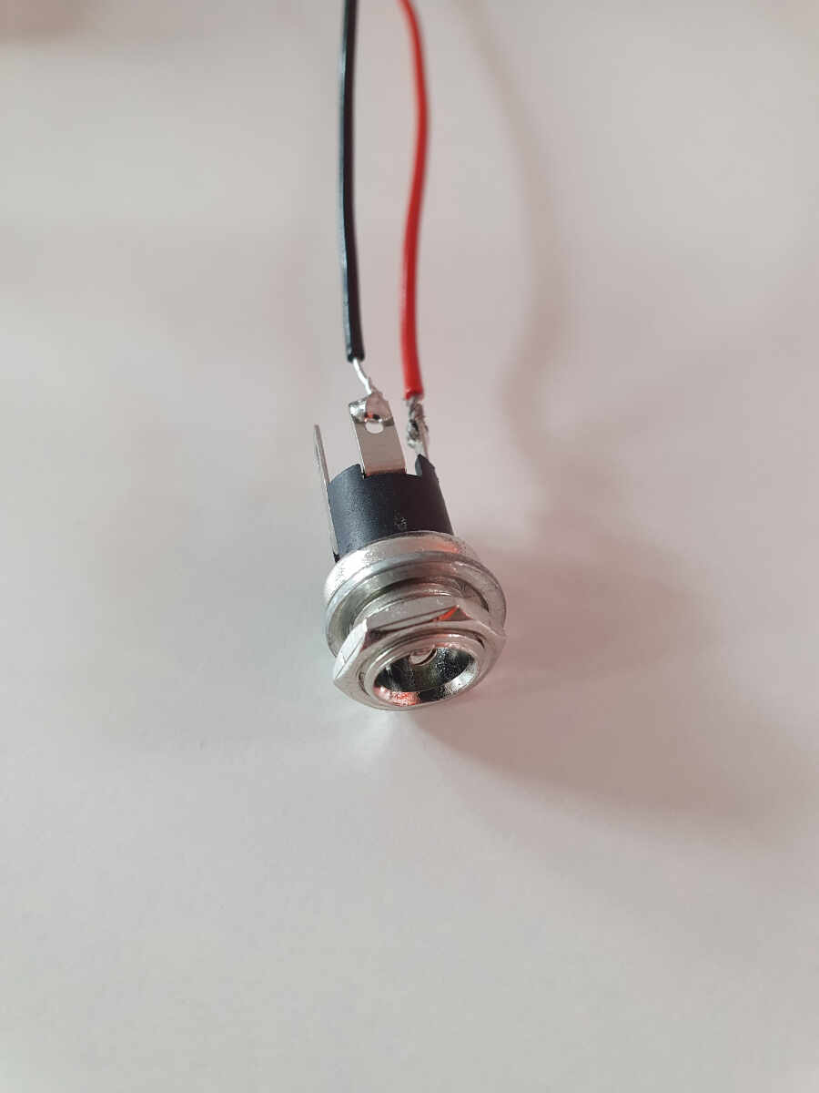
I just added some heat-shrink sleeves to prevent short circuit.
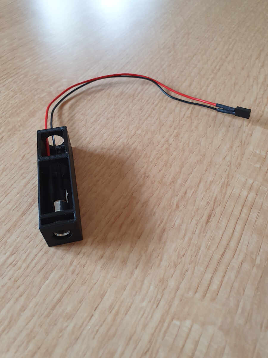
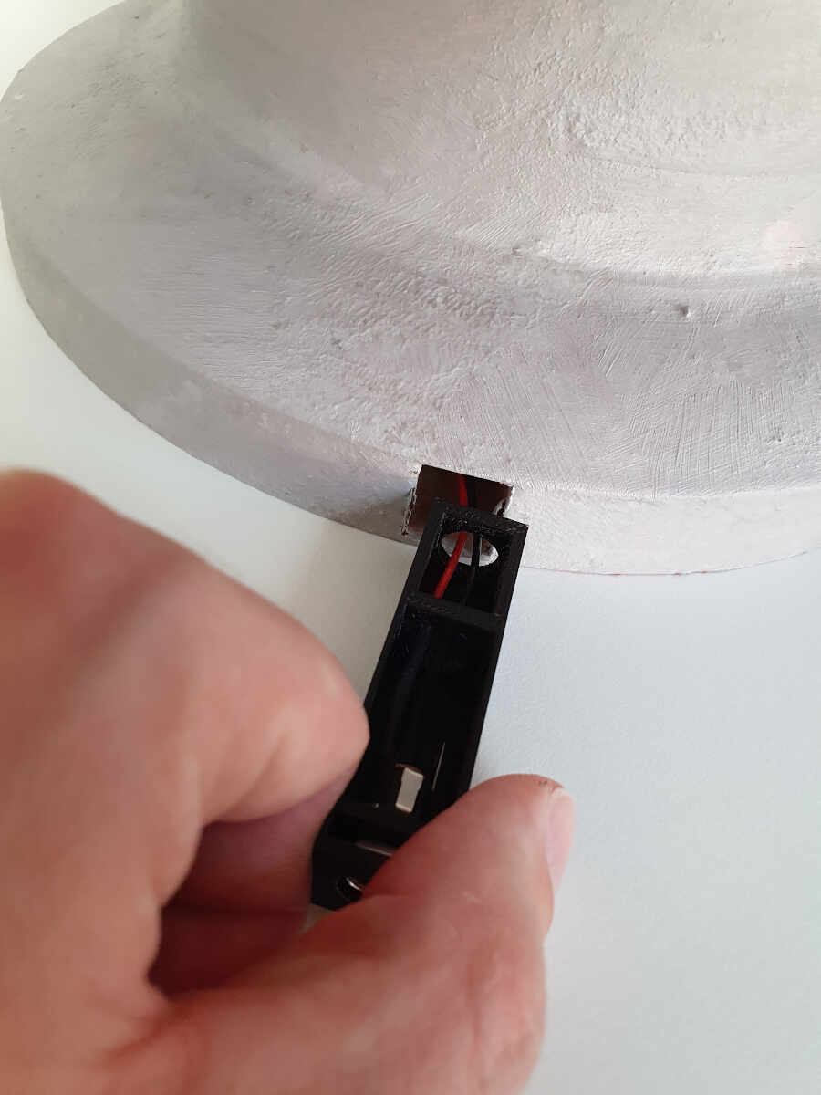
I inserted the jack socket in a 3D printed enclosure.
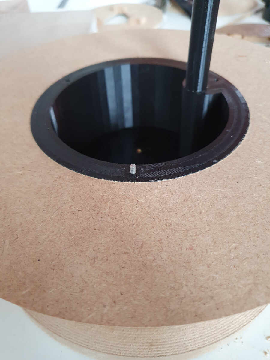
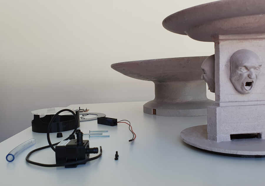
I screwed the pump in place with the M3x8mm plastic screws.
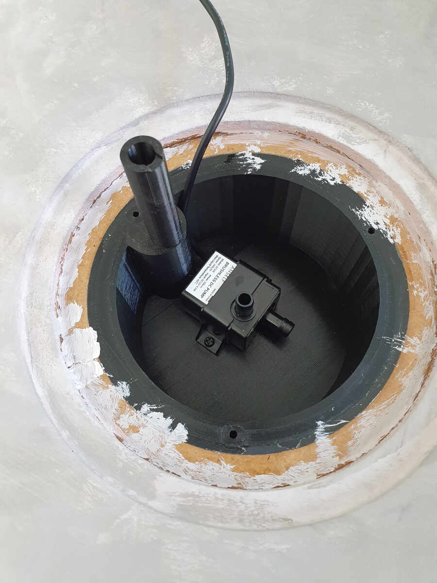
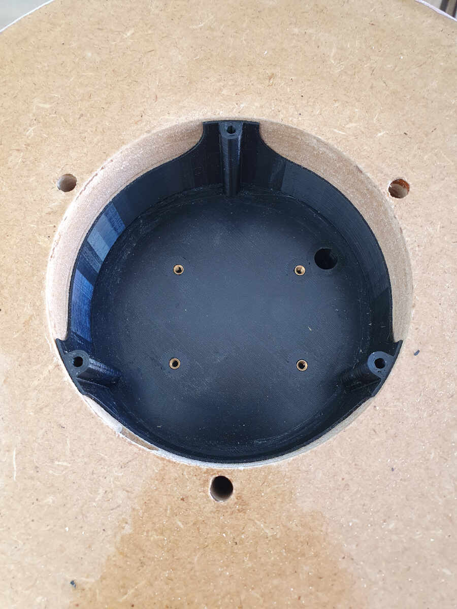
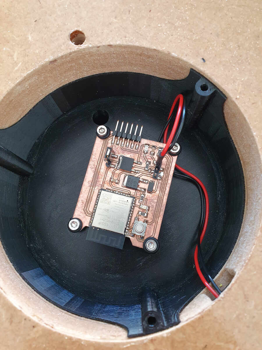
I placed the electronics spacer/enclosure in the fountain base.
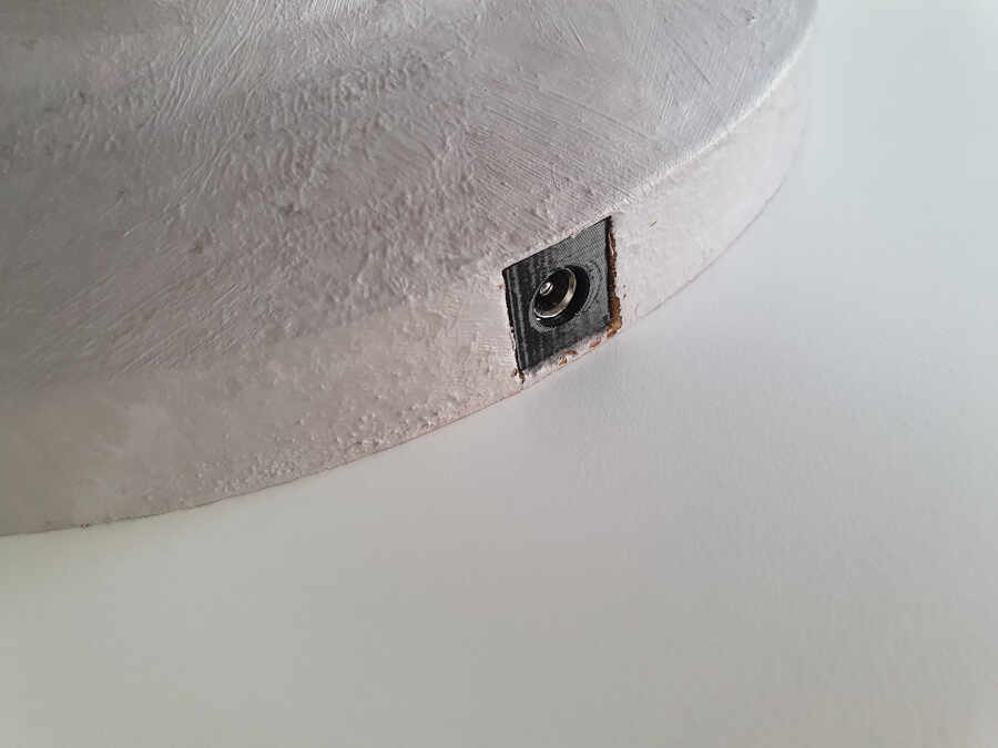
I inserted the jack socket enclosure in the slot made for it.
It gives a pretty good looking result.
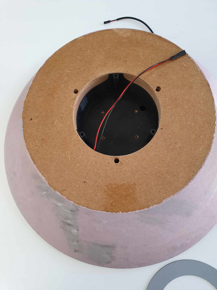
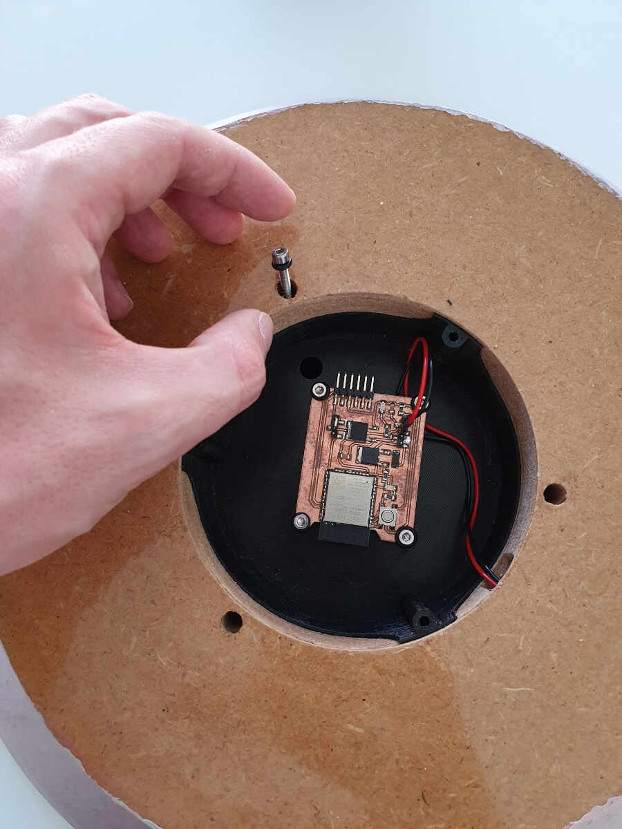
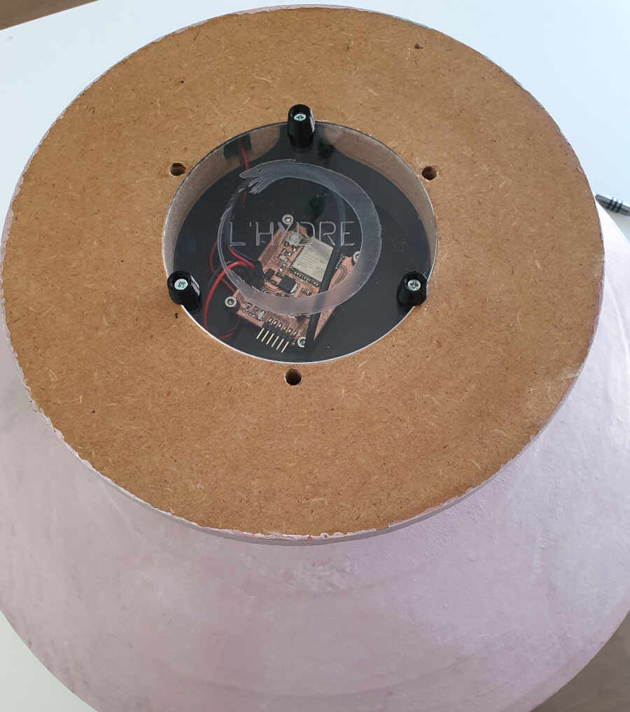
Here is a picture to let you see it from the bottom.
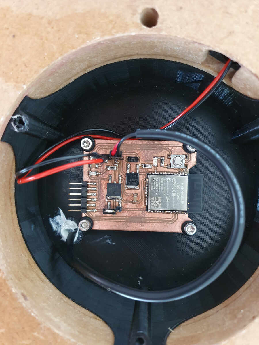
Then I mounted the electronics with the M3x10mm screws.
I connected the jack socket to the board.
Here is a test of the electronics without the pump. The video shows that the red LED is either turned off or it blinks rapidly. The pump can therefore be controlled with PWM signals.
Testing the electronics without the pump connected
I first connected a tube to the top part of the fountain. The other extremity of this tube goes to the pump.
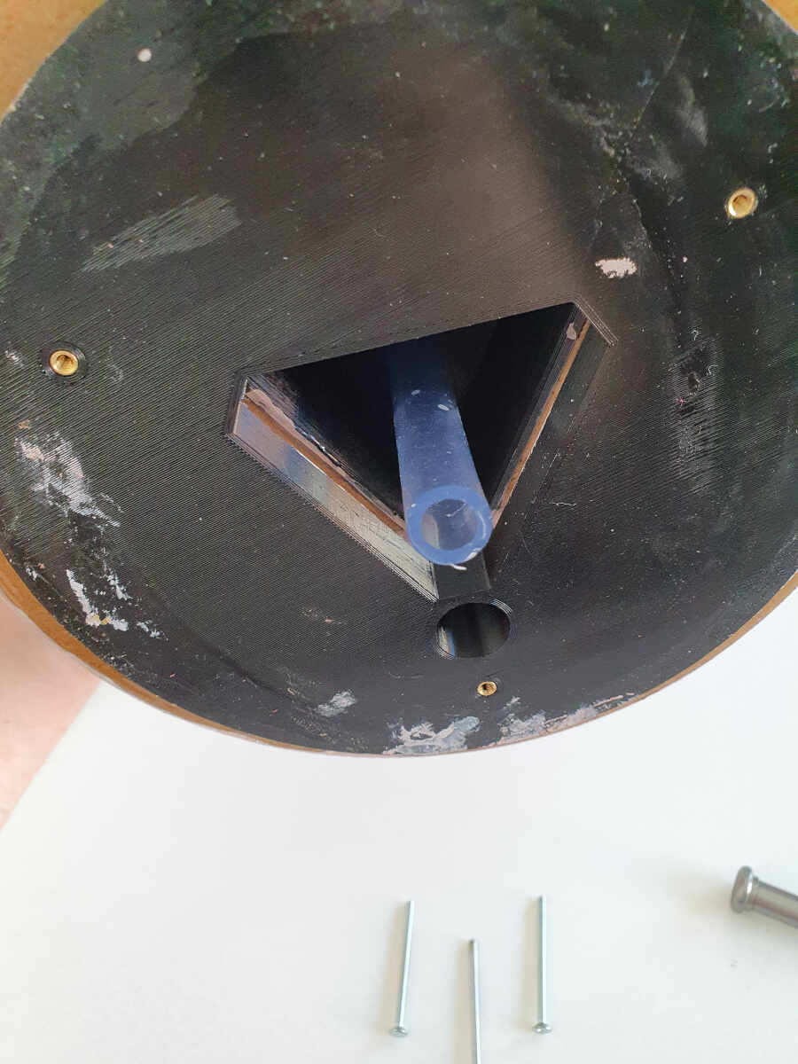
I added M3x16mm screws with o-rubber rings to prevent leakage.
I added the laser-cut rubber seal between fountain cavity and the top of the fountain and I screwed both parts together with enough tension to compress the rubber seal in between.
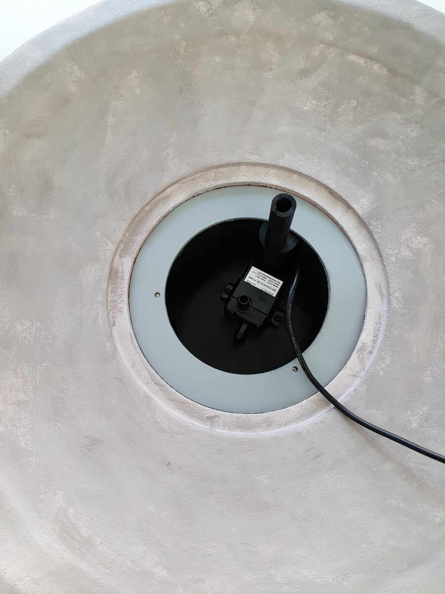
Then I connected the pump to the PCB board and I added silicone in the hole coming from which the pump cable goes out.
Finally I added the Plexiglas window and three bases fixed with M3x50mm.
Now it's time for results.
Results
Here you'll see the final results. Once the device is connected to the application (see the GUI Programming section for more information), the flowrate can be modified by sliding the range slider from 0 to 20. The value beneath is updated each time the BLE device receives a new command.
Testing the fountain through the interface