Week 3 - Computer Aided Design
This week will cover the topic of Computer-Aided Design (CAD). CAD is a computer technology which aim is products design, design assistance and documentation of the design process.
There are differents kinds of CAD softwares. Some of them are 2D or 3D-oriented while others can do both. Other features such as simulation functionalities may be part of the CAD softwares depending on their utility.
2D Design
2D Design softwares are mostly used for technicals drawings or for image editing and photo retouching. One major difference split 2D Design softwares into two distinct categories: 2D Raster and 2D Vector Graphics editors. The difference is that a picture created with a 2D Raster Graphics software consists of a matrix of pixels while a picture created with a 2D Vector Graphics software is a vector image, which means that the image is made up of points, lines, and curves that are based upon mathematical equations, rather than pixels. This difference is noticeable when zooming in. A 2D vector image will indeed never loose resolution since the curves are constantly recomputed while zooming in contrary to a 2D Raster picture that has a limited resolution due to its predefinite number of pixels. Hereunder several available sofwares are presented into their category.
2D Raster Graphics
GIMP is a Free and Open Source Image Editor. Its functionalities can be expanded by downloading BIMP, a GIMP plugin providing a lot of batch functions to manipulate images, such as: resize, crop, flip and rotate, blurring and sharpening, etc.
Photoshop is much more powerfull than GIMP but it is a commercial drawing solution provided by Adobe. Nevertheless a 30 days free trial version can be downloaded on their website.
MyPaint is an easy-to-use painting program which works well with Wacom graphics tablets and other similar devices. MyPaint is available for Microsoft Windows, macOS, and Unix-like operating systems.
Krita is a professional FREE and open source painting program. It is made by artists that want to see affordable art tools for everyone. According to TECHRADAR, Krita is the best free painting software in 2019 and 2020. It is available for Microsoft Windows, macOS, and Linux.
ImageMagick is an Open Source software to create, edit, compose, or convert bitmap images. Its features functions to resize, flip, mirror, rotate, distort, shear and transform images, adjust image colors, apply various special effects, or draw text, lines, polygons, ellipses and Bézier curves. It runs on Linux, Windows, Mac Os X, iOS, Android OS, and others. This is a powerfull tool. I used it to resize or crop pictures for my website and reduce the files size.
GraphicsMagick is an Open Source Image Processing System originally derived from ImageMagick. GraphicsMagick is available for Microsoft Windows, macOS, and Unix-like operating systems.
2D Vector Graphics
Libre Office - Draw is a vector graphics editor available in the open-source office suite "Libre Office"./p>
FreeCAD is an Open Source software that equally allows 2D and 3D design.
3D Design
Applications with 3D Design softwares are much wider than with 2D Design softwares. 3D Design softwares are used by artchitects (e.g sketchUp) to sketch houses, as well as by engineers (e.g SolidWorks, AutoCAD, CATIA, ...) to design products and run simulations, by 3D modellers and animators (e.g Blender, Rhino, ...) to create characters and animate movies, or by game developpers (e.g Unity, Unreal). Most of the 3D softwares embed a render function that renders a realistic image of the designed product.
Note that most of the files created with 3D Design software can be shared with other users. Some communities such as GrabCAD even offer services like Free CAD Library. To share files it is worth to know which format is usually used. The most common file extensions are STL, OBJ, STEP and Alembic.
Hereunder the softwares are presented into several categories based on their use and capabilities:
- B-Reps CAD tools
- 3D animation tools
- Indutrial CAD tools
- Voxel tools
- F-Reps CAD tools
- mods
- Game engines
- Simulation tools
B-Reps CAD tools
Solvespace FreeCAD Open CASCADE AutoCAD Inventor Fusion 360 education SolidWorks Visualization xDesign Onshape3D animation tools
Maya Alias 3ds Max Cinema 4D HoudiniIndutrial CAD tools
Catia Creo NX ACIS ParasolidSketchUp
Voxel tools
MagicaVoxel Monolith OpenVDBSketchUp
F-Reps CAD tools
OpenSCAD OpenJSCAD Kokompe Kokopelli Antimony libfiveSketchUp
mods
modsSketchUp
Game engines
SketchUp
Simulation tools
SketchUp
Audio and Video
FAB ACADEMY 2020 source
20200205 Computer Design from Academany on Vimeo.
My Assignment
This week I tried to use as many CAD softwares as possible.
Amoung CAD softwares I had already used SolidWorks and Photoshop. I was therefore curious to learn more about their Open Source "equivalent", respectively FreeCAD and GIMP.
Another program I was really interested in (and I still am) for its rendering and animation capabilities is Blender. So I followed the official tutorial about fundamentals for getting started. Afterwards I imported files from SolidWorks into Blender.
Here there is a trick. In SolidWorks select the STL format when saving the file you want to import in Blender then click the "options" button and make sure to tick the "save all components of an assembly in a single file" checkbox if you want to convert an assembly.
I also had a look on the possibilities that Draw | LibreOffice offers but I found it difficult to enter dimensions. For that reason I preferred to leave that program aside and focus more on another 2D vector software : Inkscape.
Finally, due to a lack of time and because I wasn't feeling confident enough with FreeCAD or Blender, I decided as a compromise to use SolidWorks to design and render one part of my project and GIMP for another one.
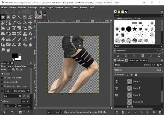
With GIMP I draw a first prototype of my smart thigh compression sleeve with Flex Sensors as a starting point and I used BIMP, a GIMP extension, to resize my pictures.
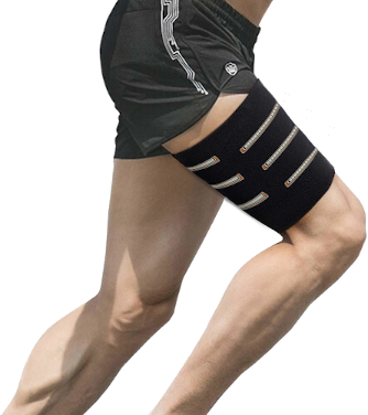
To create that picture, I used two pictures and I added different layers. First I cut out the leg from the background by using the Fuzzy (magic wand) tool. Then I erased the brand of the original thigh sleeve with the Clone tool. After I added different layers with the sensors pictures that I deformed with the Unified Transform tool and I finished the work by adding a shadow filter beneath the thigh.
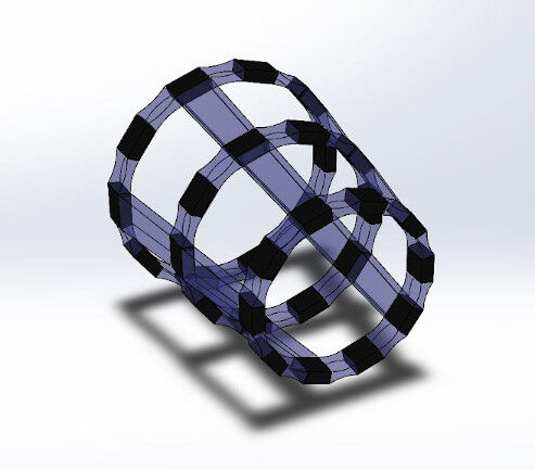
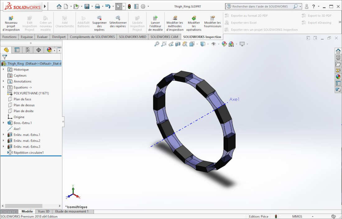
With SolidWorks I sketched a second prototype of my smart thigh compression sleeve based on the article of Jennifer C. Case et al.: "Sensor enabled closed-loop bending control of soft beams" .
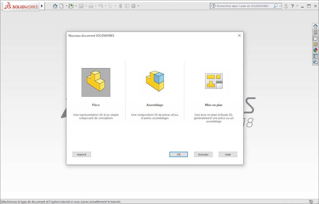
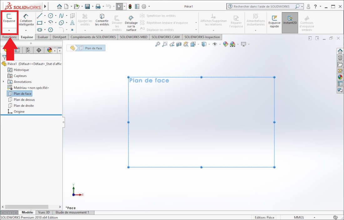
To create this 3D model I started SolidWorks and I clicked on New -> Part.
Then I selected the front plane and I clicked on Sketch.
Afterwards I drew the Sketch and at the end, I used the function extrude to create a volume.
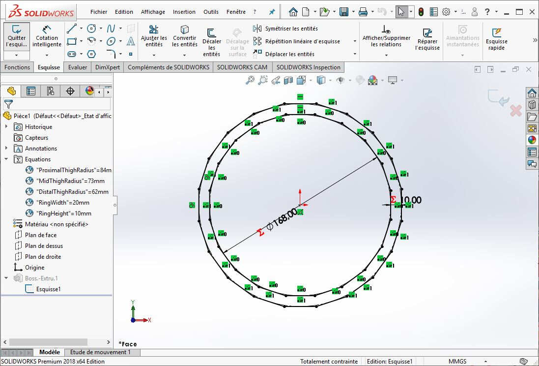
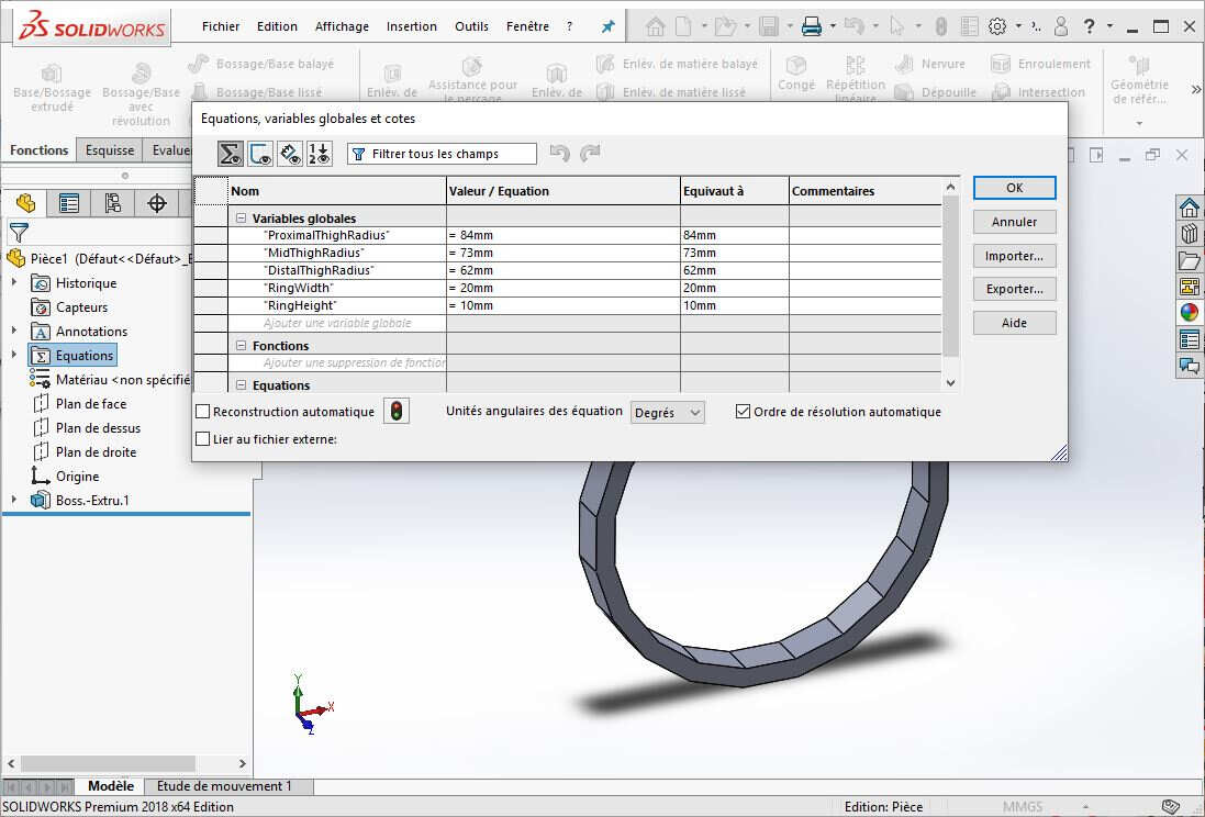
To ease my work later, I set global variables to define the dimensions of the part.
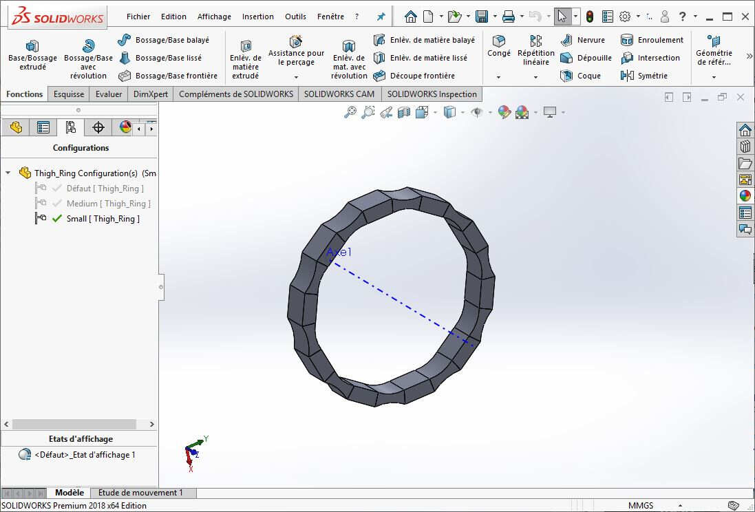
I also set three different part configurations as shown in the picture below, each with a different diameter.
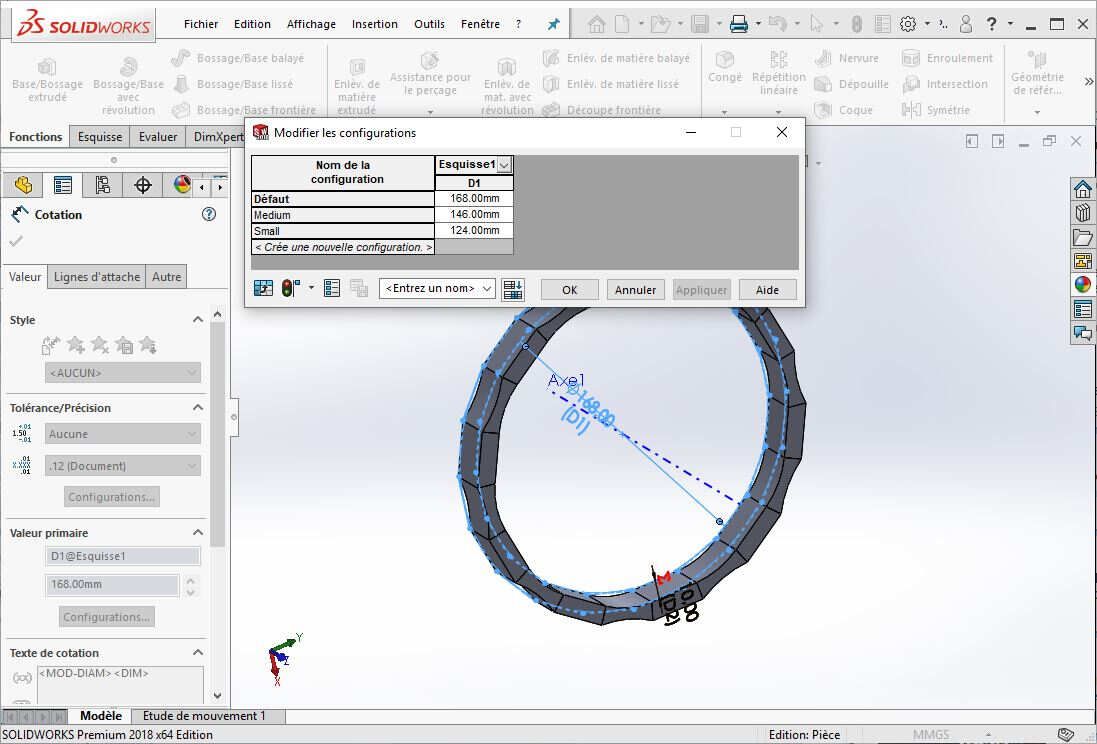
Now in the configuration folder I can pick the part I want.
To finish the first part I changed the color material. The procedure is described here.
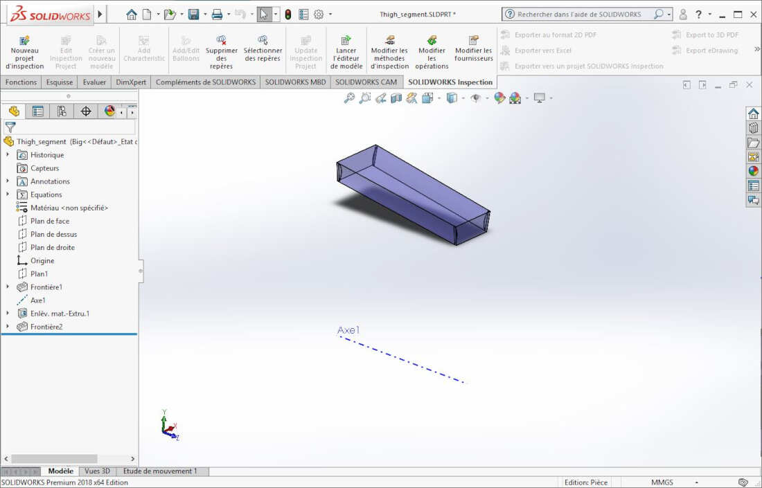
Afterwards I similarly created the second part, a silicone connector:
Finally I created an assembly by clicking on New -> Assembly. Then I inserted the parts one by one by clicking on insert components. The procedure is described here.
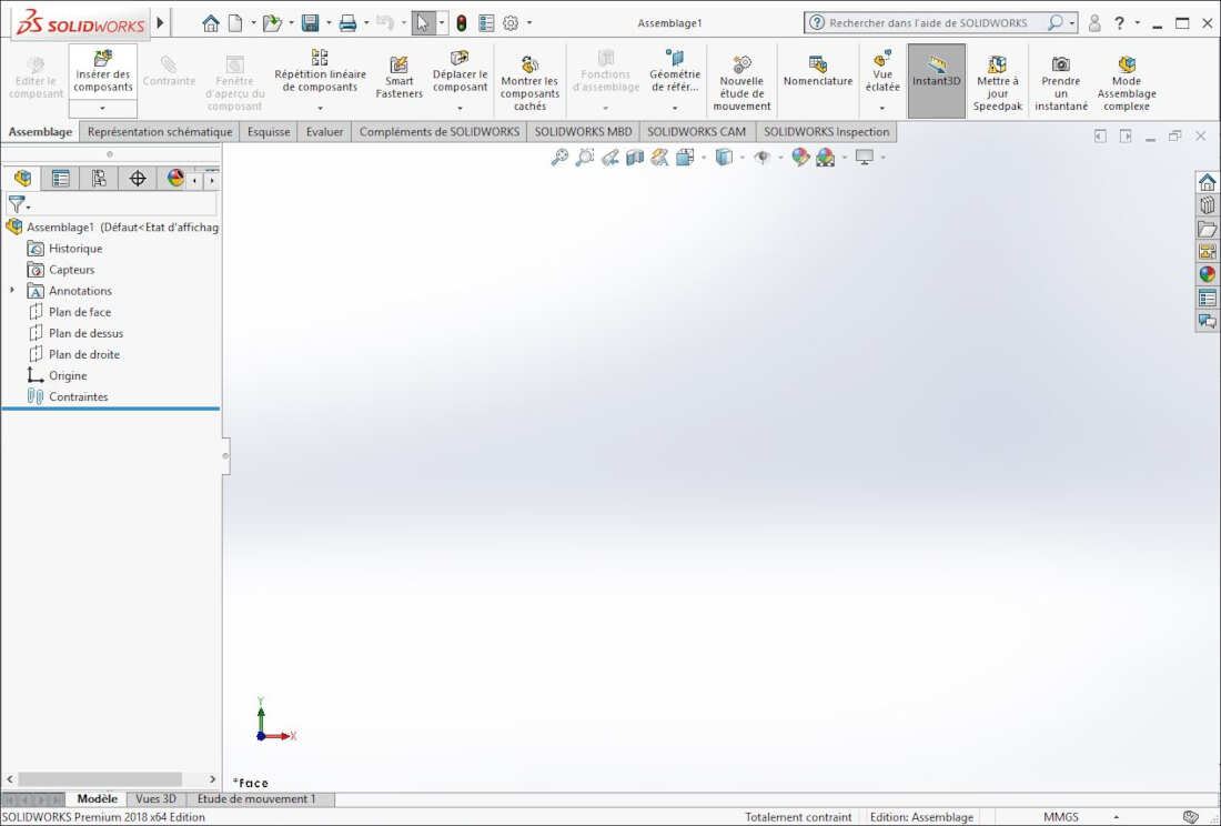
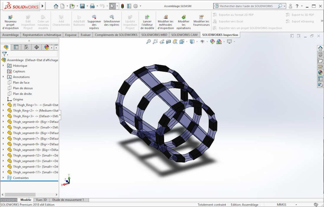
I set a bunch of constraints as explained in this tutorial.
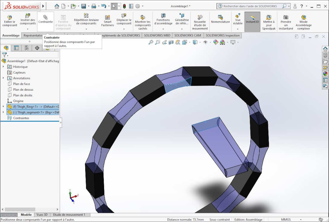
Finally, by adding a middle ring, two extremity rings and ten silicone connectors, I ended with the following result:
Yet I still have ideas for improvements. I downloaded free CAD files of a leg and of human bodies from TURBOSQUID and Free3D.
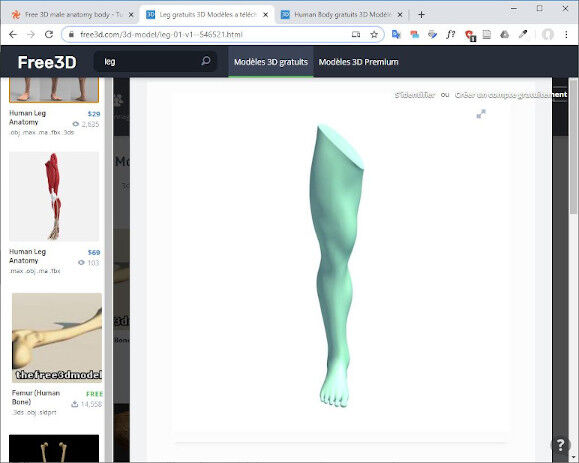
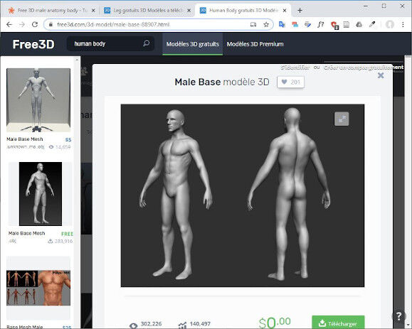
In the future I'd like to use Blender to deform the part I designed with SolidWorks in such a way that it would fit the free CAD leg model.
Files
WEEK 6 - 3D Scanning and Printing
To design the branch screens I used Sapling, an Add-on of Blender that allows to create trees. To enable it go to "Edit -> Preferences". Then, in the search box, type "Sapling" and check the checkbox at the right hand side of the addon. To add a tree to you scene click on "Add" or press "Shift + A" and select "Curve -> Sapling Tree Gen". To learn how to adjust the parameters of the tree I followed this YouTube tutorial and I red this Blender forum article.
Once I finished to design and place the trees on their support I still had to cut their heads. To do it I first exported the file as a .STL file that I imported once more as a mesh in a new Blender file. To cut the heads of the trees I first drew a cube that I placed on the top of the trees, then I added a Boolean modifier to my trees mesh and I applied a difference.
There was a subtlety before exporting the object as an .STL file. Indeed I first had to set the Bevel resolution of the trees to a higher number, otherwise their section would appear with sharp angles. Therefore in the right panel "Object data properties -> Geometry : Bevel", I modified the "Resolution" parameter from 1 to 10 and the shape of the tree trunks became smoother.
As I needed two branch screens for the scenography, I also used the "Symmetry" function of Blender to duplicate the original screen. First I set the pivot point to the center (3D cursor). Then I selected the object to symmetrize and I pressed "Shift + D" to duplicate it. Directly after that I pressed "s" followed by "x" (that could also be y or z depending on the direction of the symmetry) then -1 (with 1 being the scaling rate of the duplicated object and minus translating the object in the opposite direction of x).