Week 17 - Wildcard Week
This week covered many digital fabrication processes such as machining, robotics, electronics, folding, digital gastronomy, materials manufacturing, biotechnologies, textiles and composites.
According to me the most interesting topics were robotics, folding, digital gastronomy, biotechnology, textiles, and composites.
- In the robotics field I would have liked to use robot arms especially for construction.
- In the field of folding, there is an entire lecture given by Eric Demaine. There are even machines that can fold structures acting as mechanisms. Related to that topic, I found the wildcard of Nicolas De Coster who coded a SVG generator to make and download MORPHABLE METAMATERIALS.
- In the field of digital food I was not very excited by 3D printing but some chefs explore digital fabrication to make digital gastronomy. A common digital application is the creation of cake molds by the use of thermoformer machine for example.
- In the field of biotechnology there are classes to learn How To Grow (Almost) Anything?.
- About textiles there is of course the FABRICADEMY. I also found two interesting wildcards. In his wildcard Amy explained how to use a brother embroidery machine and 2D design software such as Inkscape and Ink/Stitch. In their wildcard Gilles, Axel and Christophe developed a linear actuator with nylon threads that mimics artificial muscles.
- Finally there was composites fields. That's the field I chose for my week assignment. I was interested by the technique explained on this webpage.
FAB ACADEMY 2020 source
20200520 wildcard from Academany on Vimeo.
My Assignment
This week assignment consisted in designing and producing something with a digital fabrication process (incorporating computer-aided design and manufacturing) not covered in another assignment, documenting the requirements that your assignment meets, and including everything necessary to reproduce it.
As I have already mentioned it above I chose to work on composites and I decided to build a wind turbine blade. To design the blade, I use QBlade. Then I milled the core of the composite material in a building foam block. Finally I used epoxy and white cotton to encapsulate the blade core and a vacuum bag to maintain the cotton sheets close to the core. In the following section I'll detail the design of the wind turbine blade. In the second subsection I'll explained my milling strategy. This subsection will be followed by the detailed mill manufacturing process. After that I'll explain how I attempted to flatten my 3D model of the blade into a 2D model with ExactFlat Online in order to precisely cut 2D pattern pieces in cotton fabrics that would cover the blade foam core. In the fifth subsection I'll describe step by step the composite fabrication process. Finally I'll make some conclusion about possible improvements of the manufacturing process. The seventh subsection includes the files I created and used to build my wind turbine blade.
Wind turbine blade design with QBlade
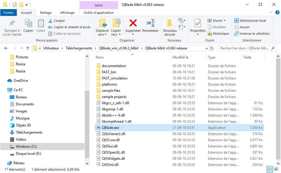
To design my wind turbine I made a little bit of research and I found an open source wind turbine calculation software called QBlade, distributed under the GPL. I just downloaded QBlade_win_v0.8.zip then I extracted its content and I double click on the QBlade.exe file as show in the figure below.
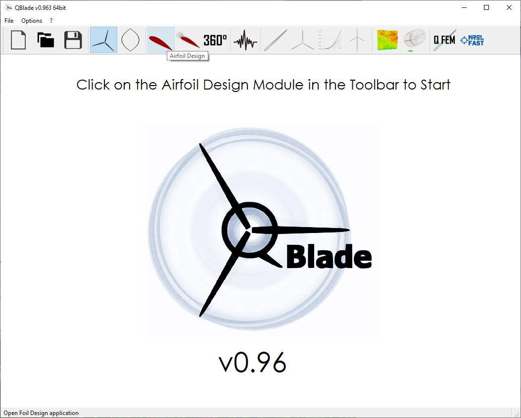
I also recommend to download the guidelines available at the downloads subsection of QBlade official website. It contains a straightforward tutorial at chapter 3 and this is the tutorial I followed step by step. The following picture shows the starting window of QBlade. First I clicked on the button Airfoil Design as suggested by both the tutorial and the starting window.
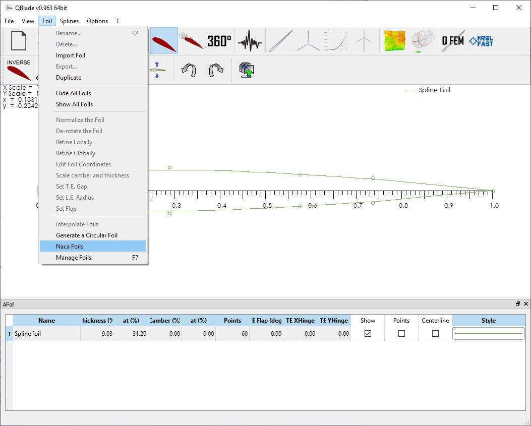
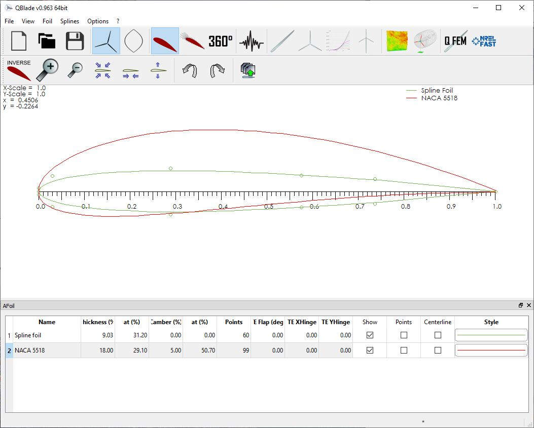
Then I selected a NACA Foils.
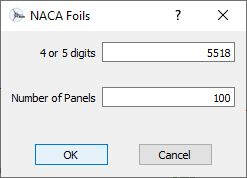
And I entered the values 5518.
After pressing OK the following picture shows the result.
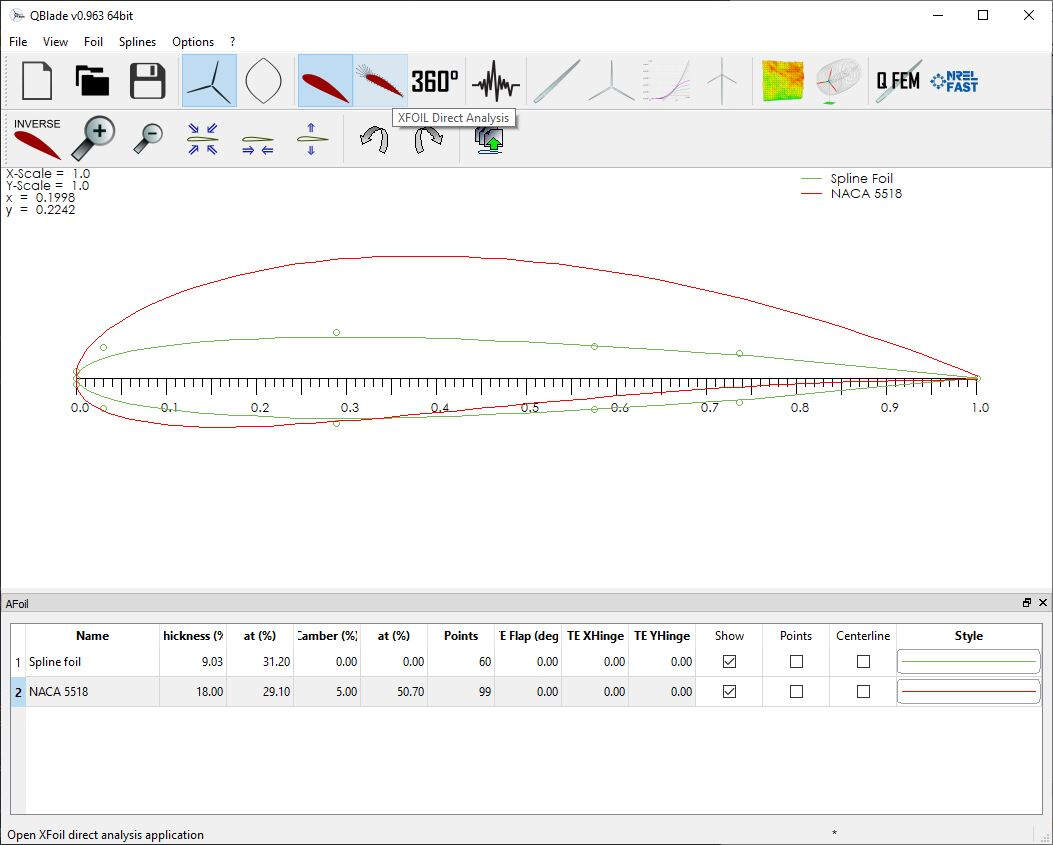
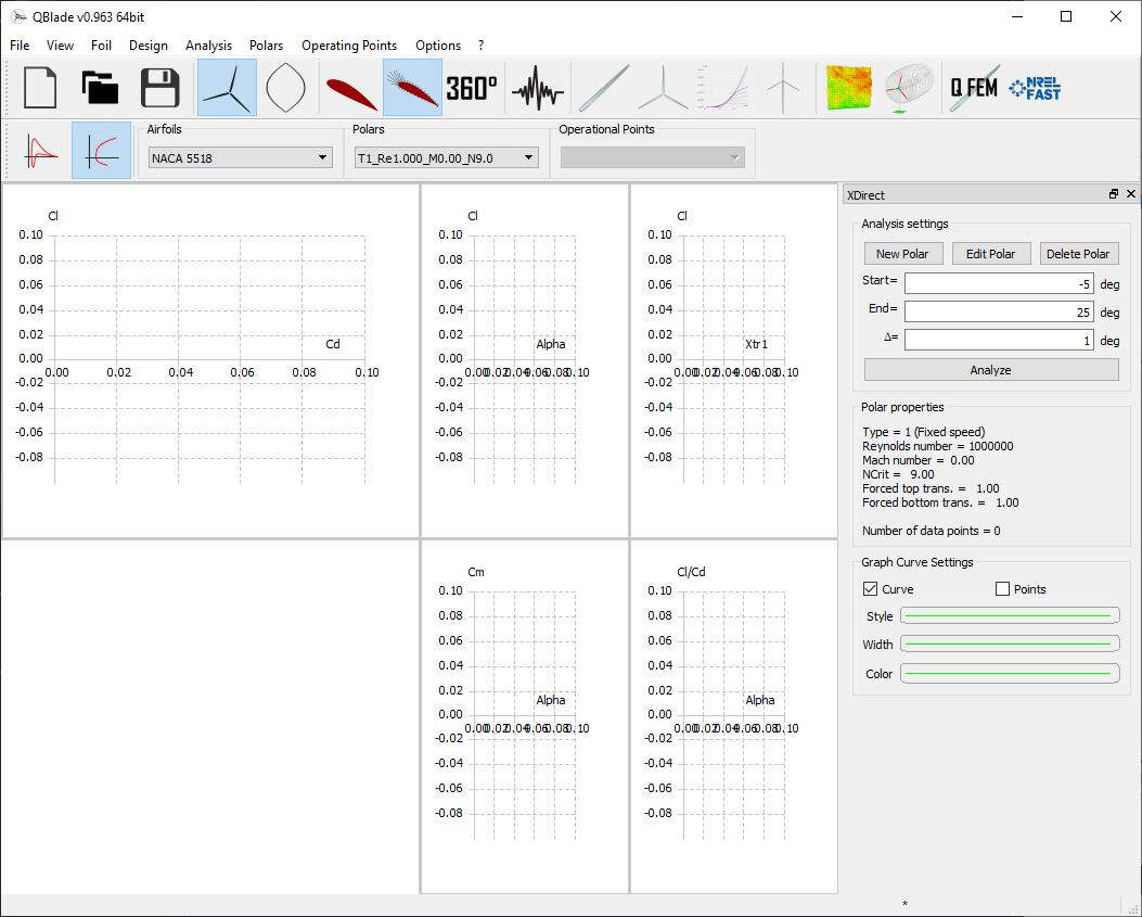
Then I clicked on the button XFOIL Direct Analysis.
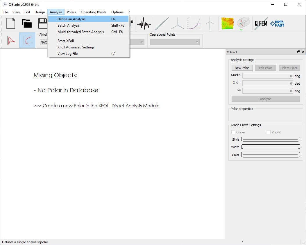
To create an analysis I clicked on Analysis -> Define an Analysis.
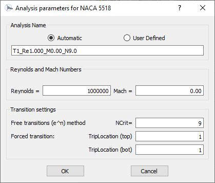
Here are the values that I used for the analysis.
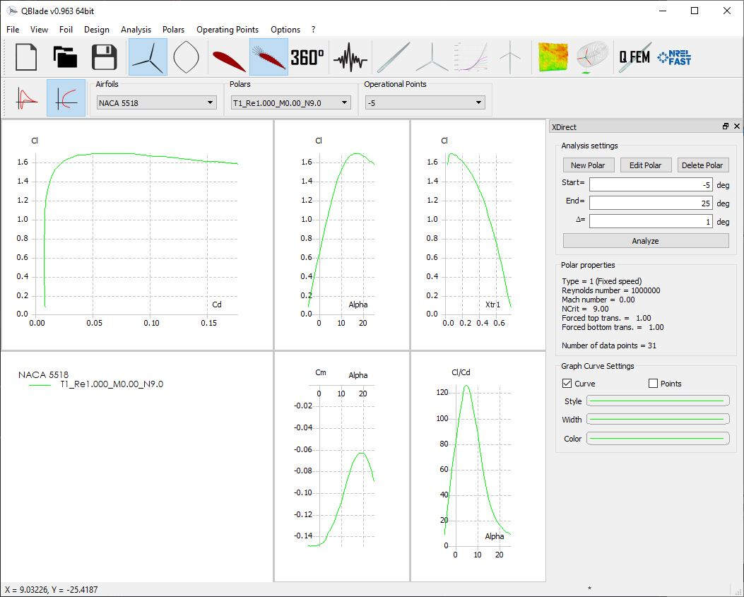
After pressing OK the right lateral panel was made available. I set the Analysis settings as shown in the picture below and I clicked on Analyze.
The following picture shows the obtained result.
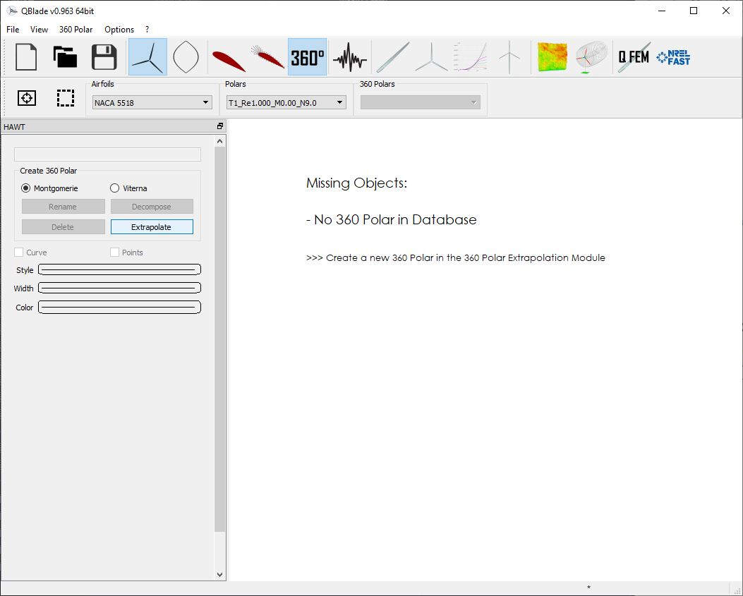
Then I clicked on the 360° icon. It is the polar extrapolation module. It is used to extrapolate the AoA range of the polar to 360° in order to simulate the behavior of the wind turbine.
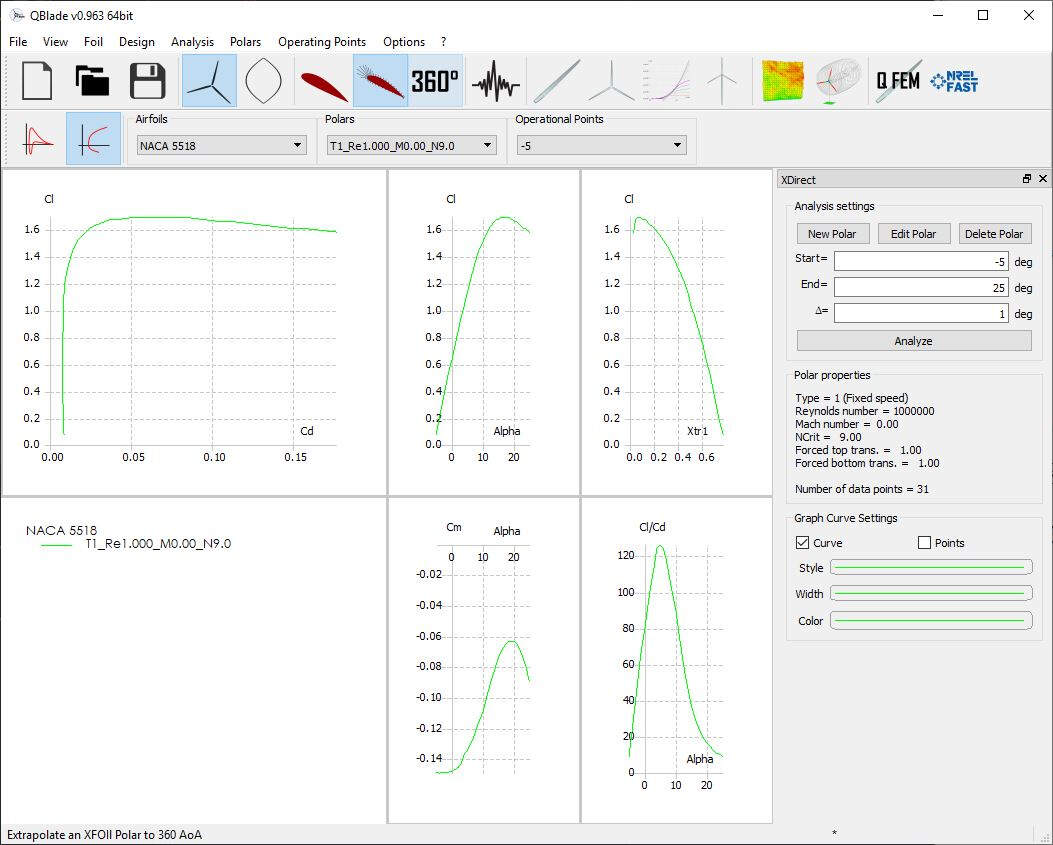
Only extrapolated polar data can be used to simulate a turbine or rotor. As a consequence I clicked on Extrapolate.
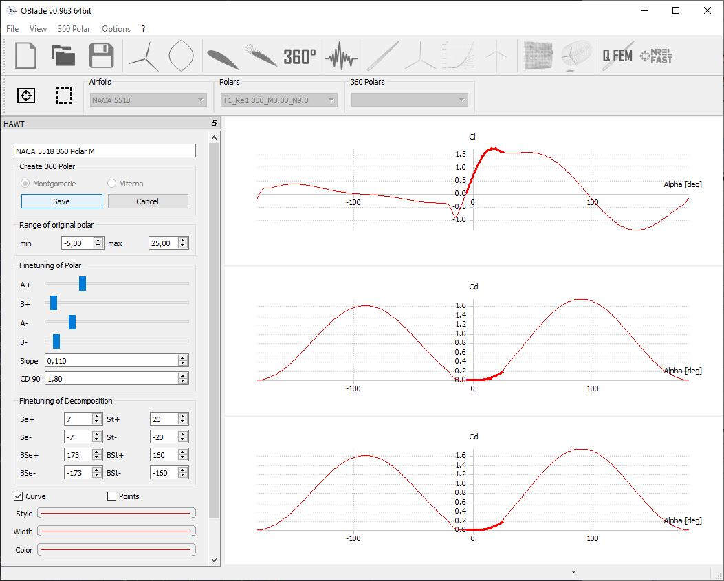
I renamed the new 360 Polar as NACA 5518 Polar M, set the parameters as shown in the following pictures and I clicked on Save.
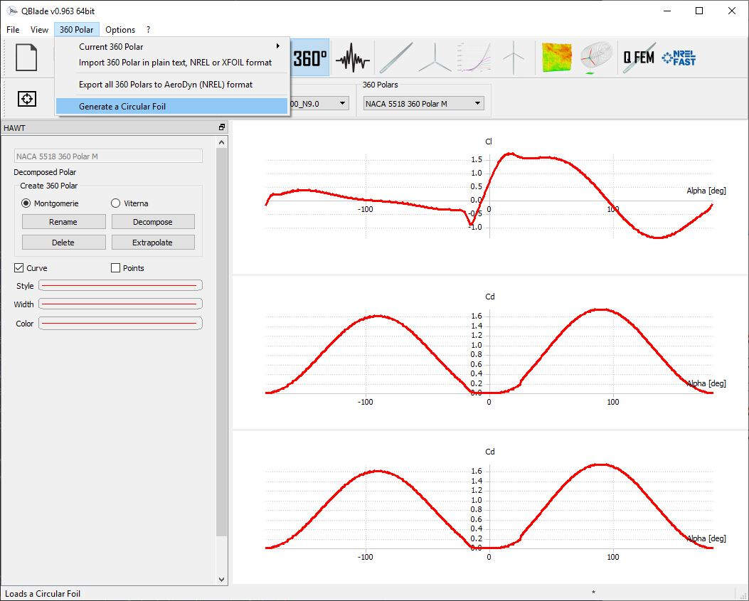
As the wind turbine blade will not only have the one same section NACA 5518 Polar M section I added a new circular section by clicking on 306 Polar -> Generate a Circular Foil.
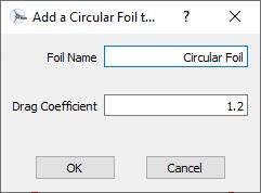
I clicked OK.
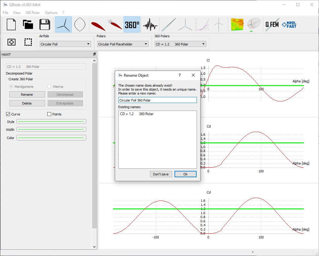
It is possible to change the Circular Foil name by clicking on Rename as show in the following picture.
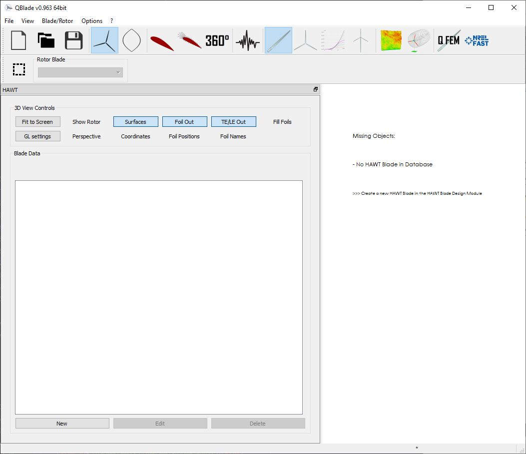
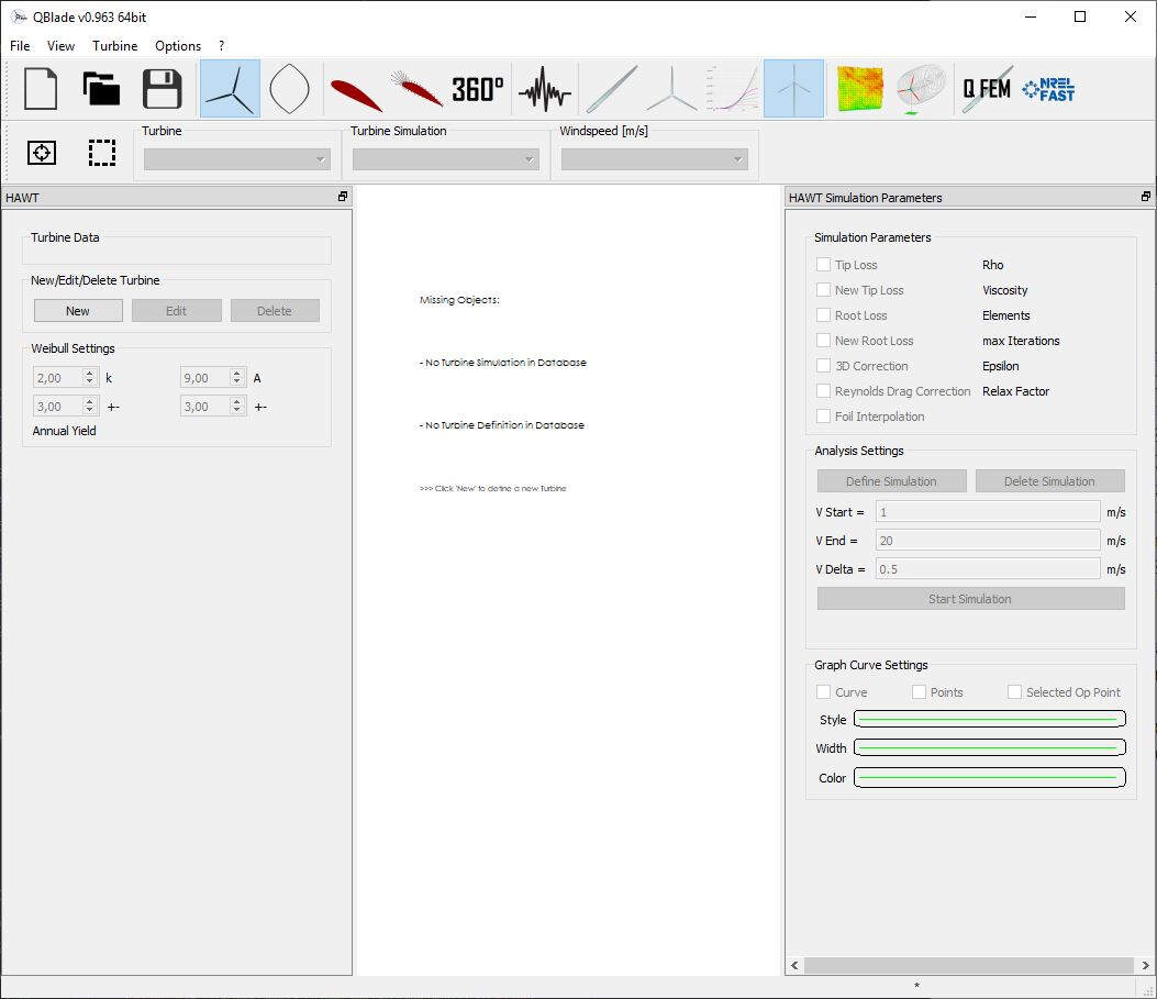
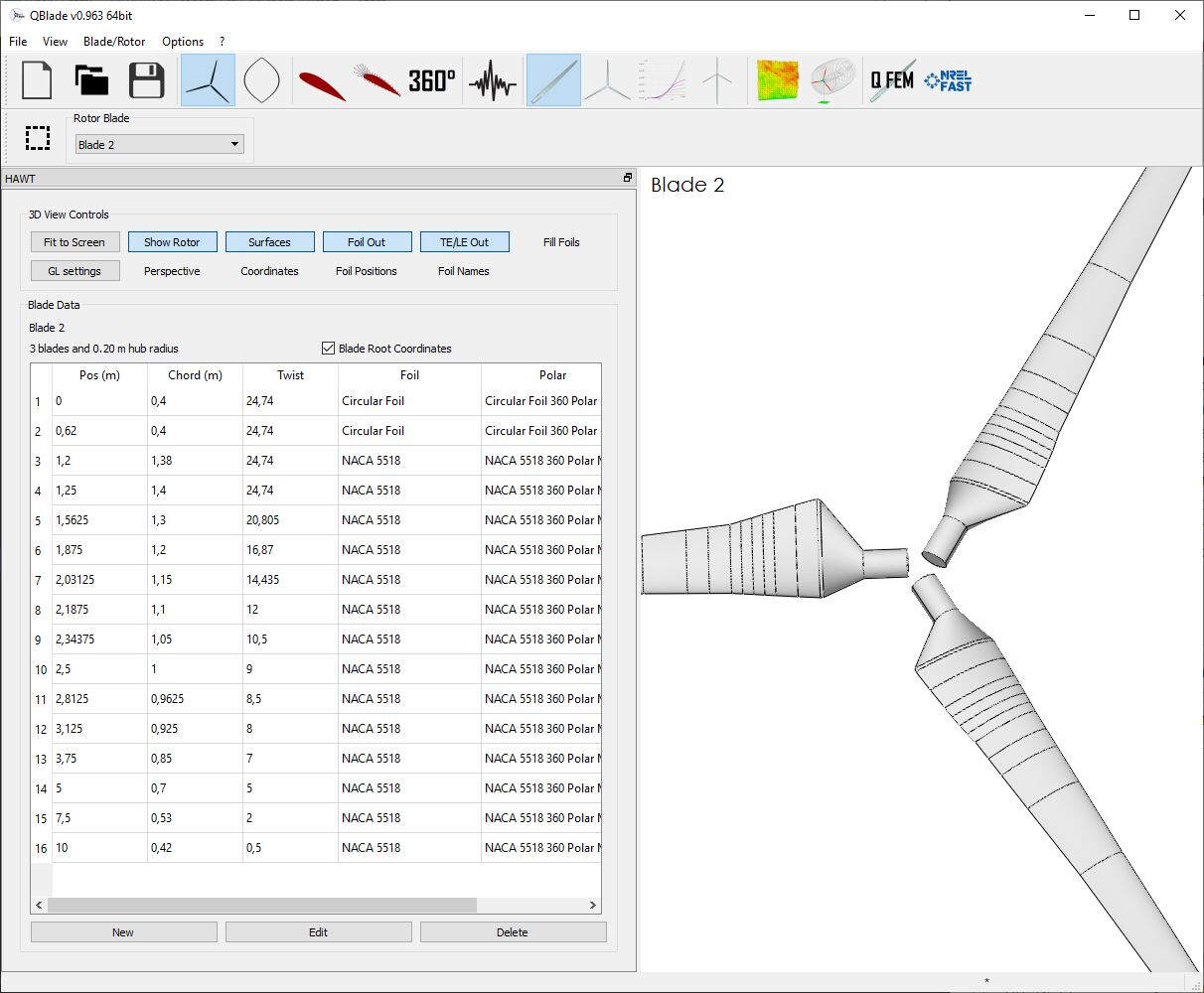
To generate the 3D model of the blade I clicked on the HAWT Rotorblade Design button and at the bottom I pressed on New.
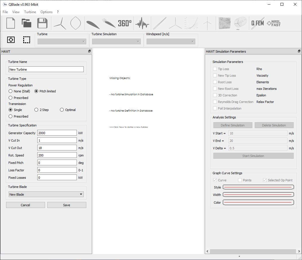
By inserting several sections and choosing their position, chord, twist and foil with respective polar, it is possible to design the turbine blades. The following picture shows the values I used. In fact I just kept the values that can be found in the above mentioned tutorial.
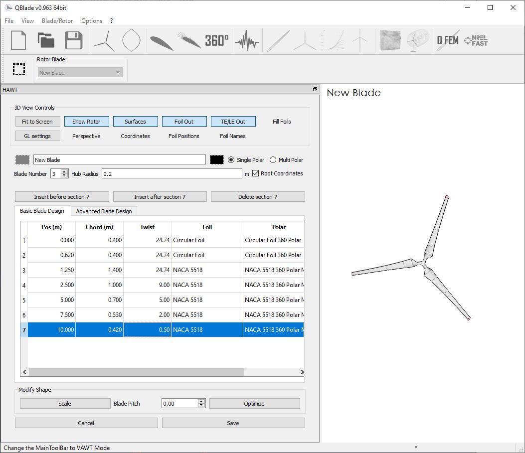
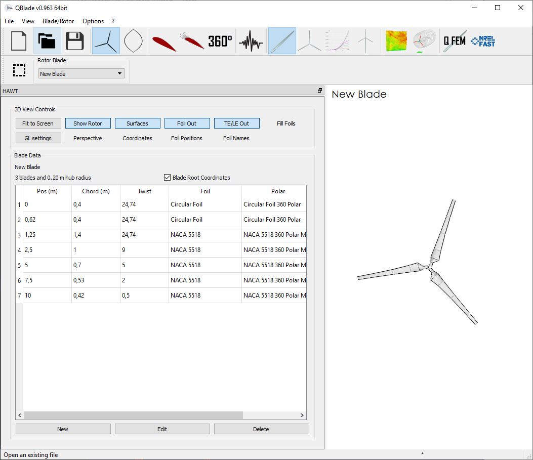
After that I clicked on Save and here is the result I got.
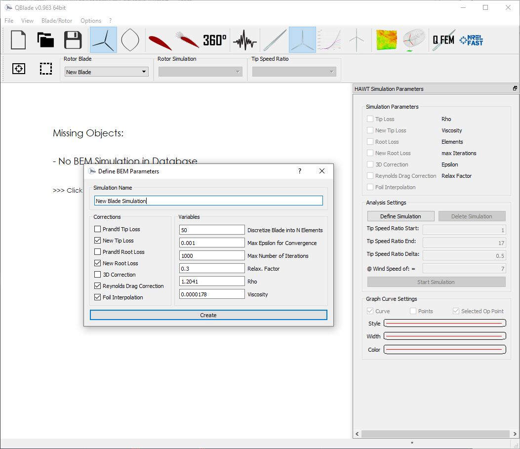
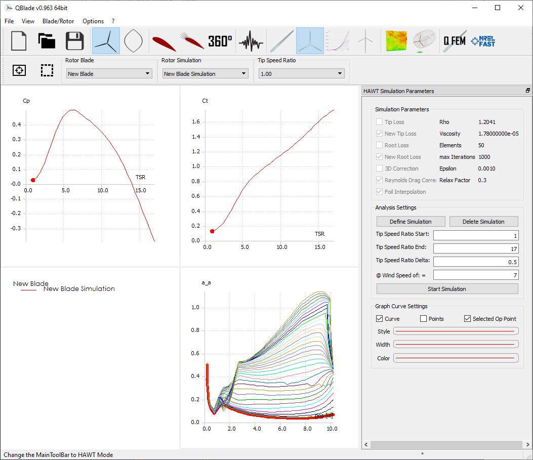
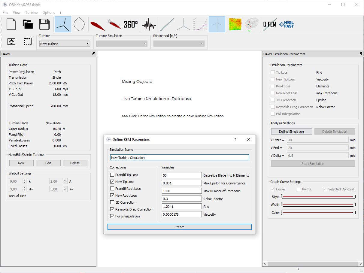
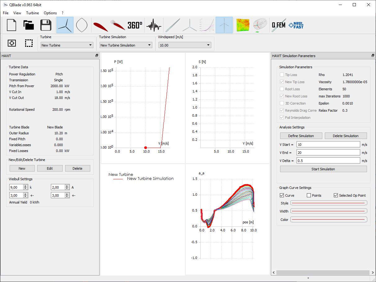
Then I created a simulation by clicking on the Rotor BEM Simulation button and on Define Simulation. For the simulation I used the values shown in the following picture and I clicked on Create.
I set the Tip Speed Ratio to 1 for Start, 17 for End and 0.5 for Delta and the Wind Speed to 7 and I clicked on Start Simulation.
Milling strategy
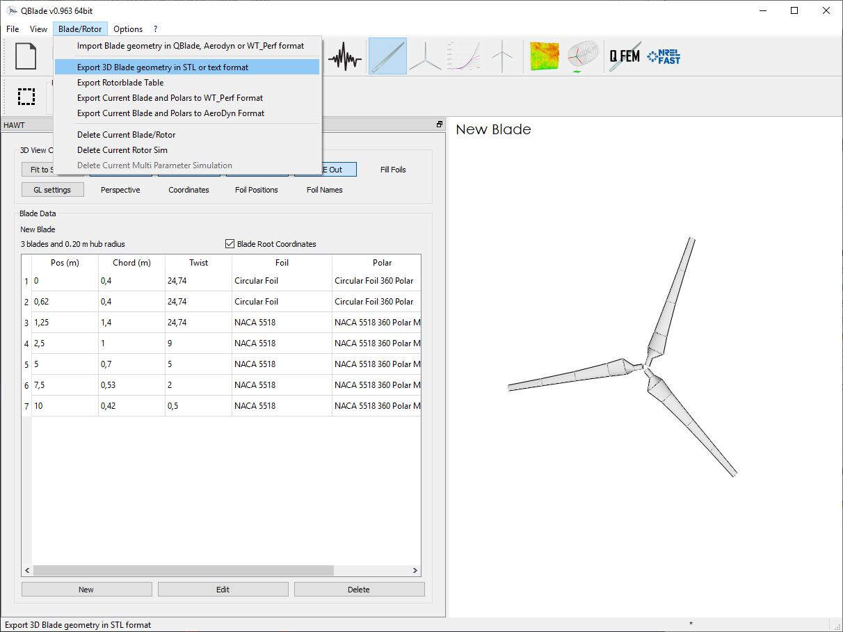
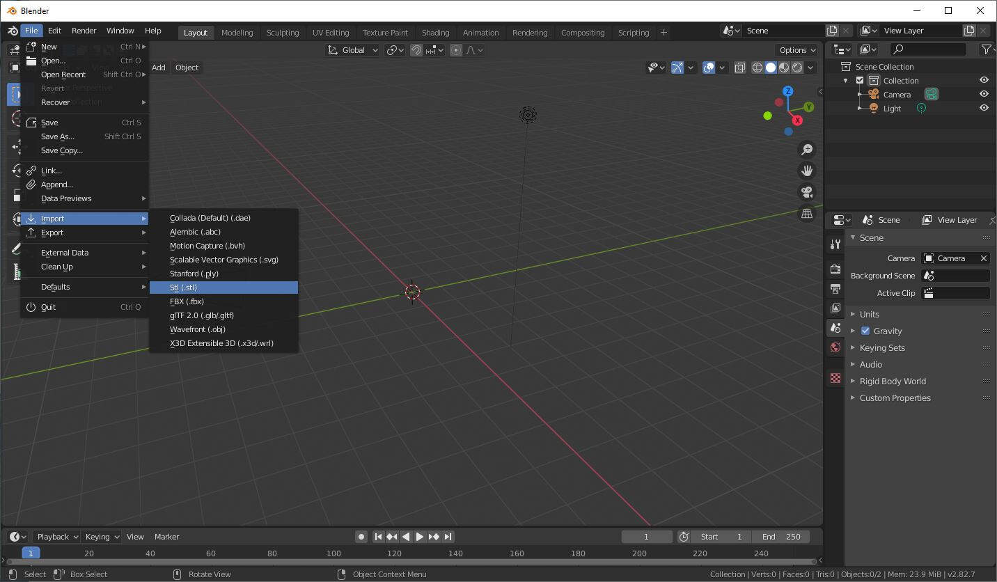
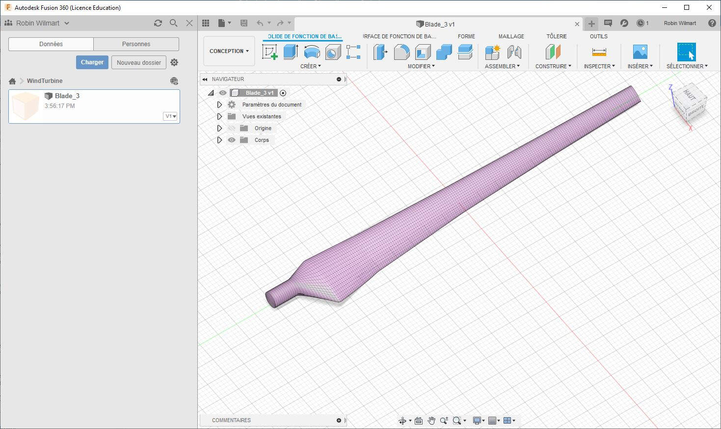
For this task I used Fusion 360, SolidWorks and Blender. First I used Fusion 360 to set the milling strategy of the blade. To do that I just imported the STL file.
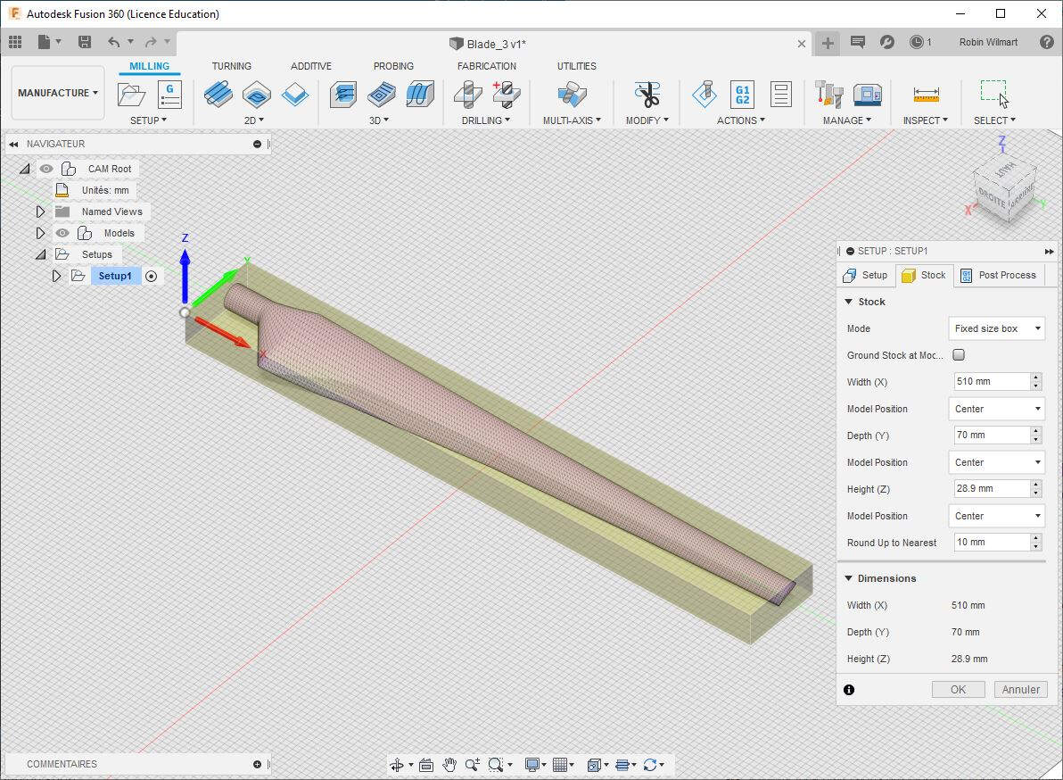
Since the blade has no flat side because it is shaped on both sides I used two different setups. The first setup is shown in the following picture. I used a fixed size box with the Height (Z) being the height of the industrial foam block that I measured precisely with a calliper.
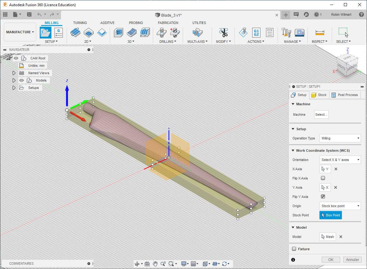
For this setup I chose the work coordinate system as shown in the picture below.
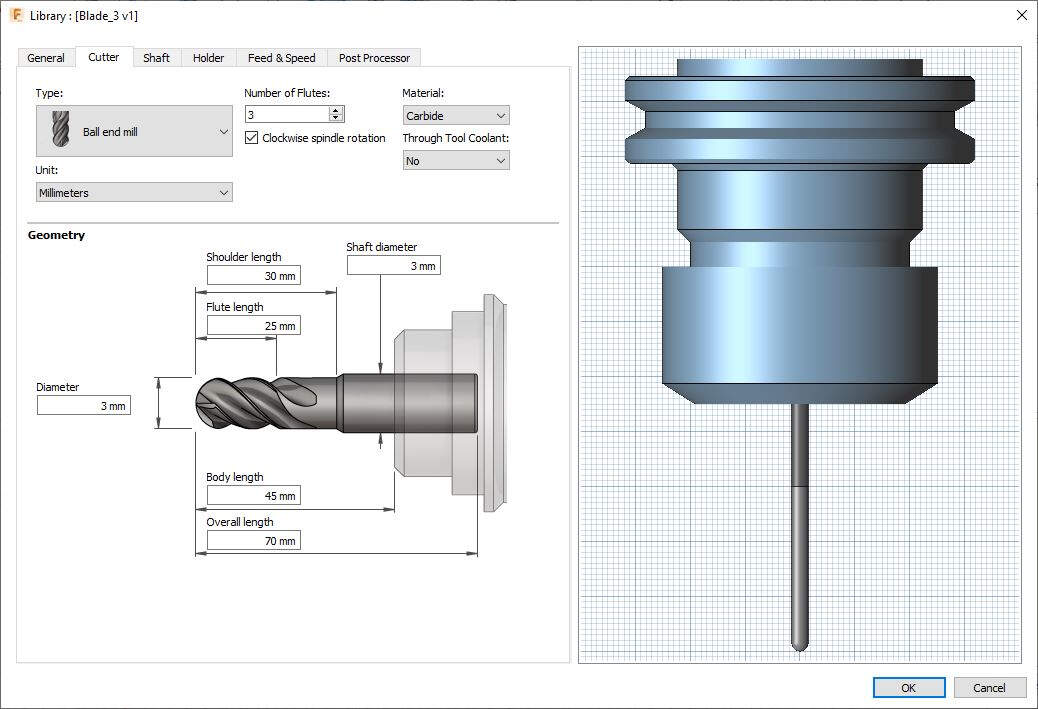
I set a 3mm Flat end mill.
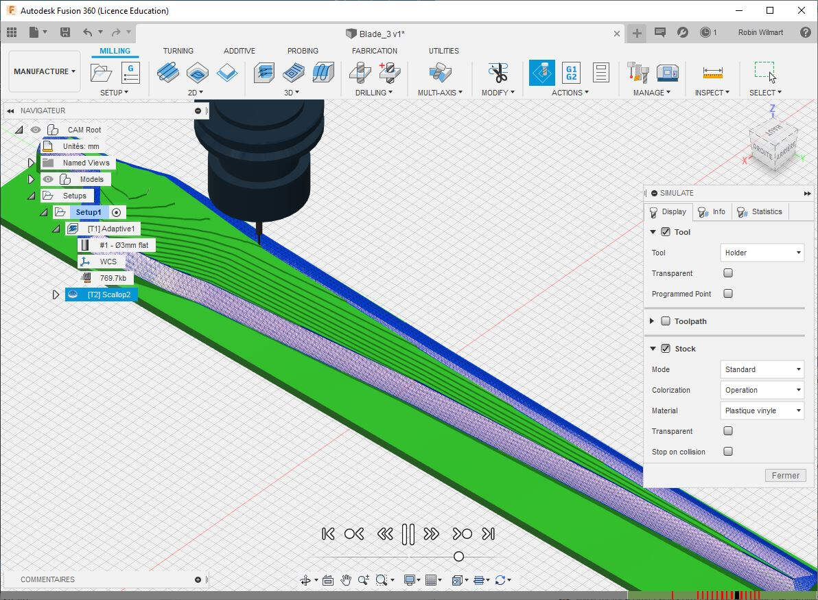
Then I made a 3D adaptive pocket cut with this 3mm Flat end mill, followed by a 3D Scallop toolpath cut with a 1mm Flat end mill. I checked the result of that cutting strategy by doing a simulation as shown below.
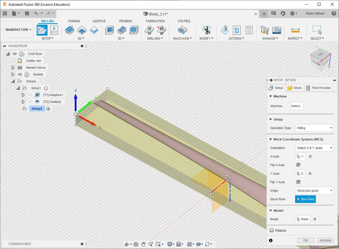
To cut the second side of the blade I decided to flip it around Fusion 360 X axis. Then I selected the work coordinate system as shown in the picture below.
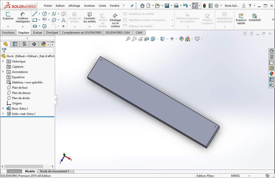
To cut the edges of the stock I draw it in SolidWorks. I made it a little bit longer along the SolidWorks Z axis to be able to add centering holes at two corners.
Then I used HSMWORKS, the CAM plugin of Autodesk for SolidWorks to generate a stock.
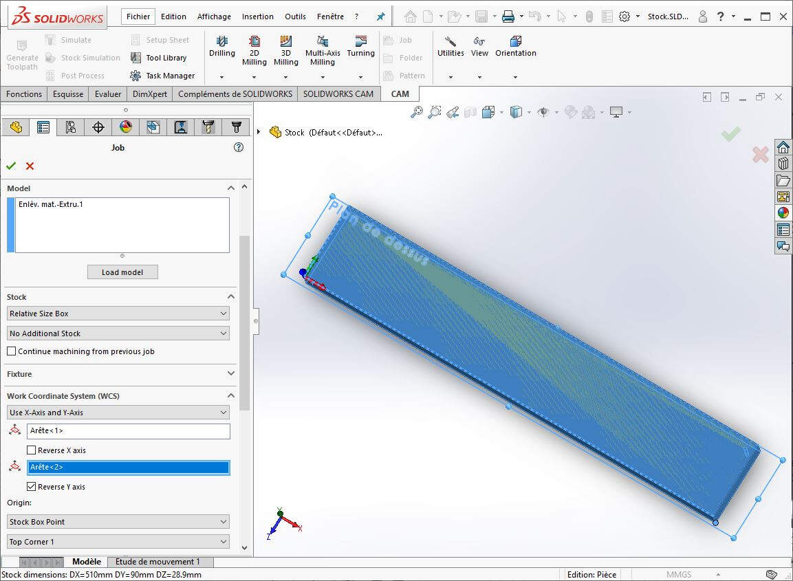
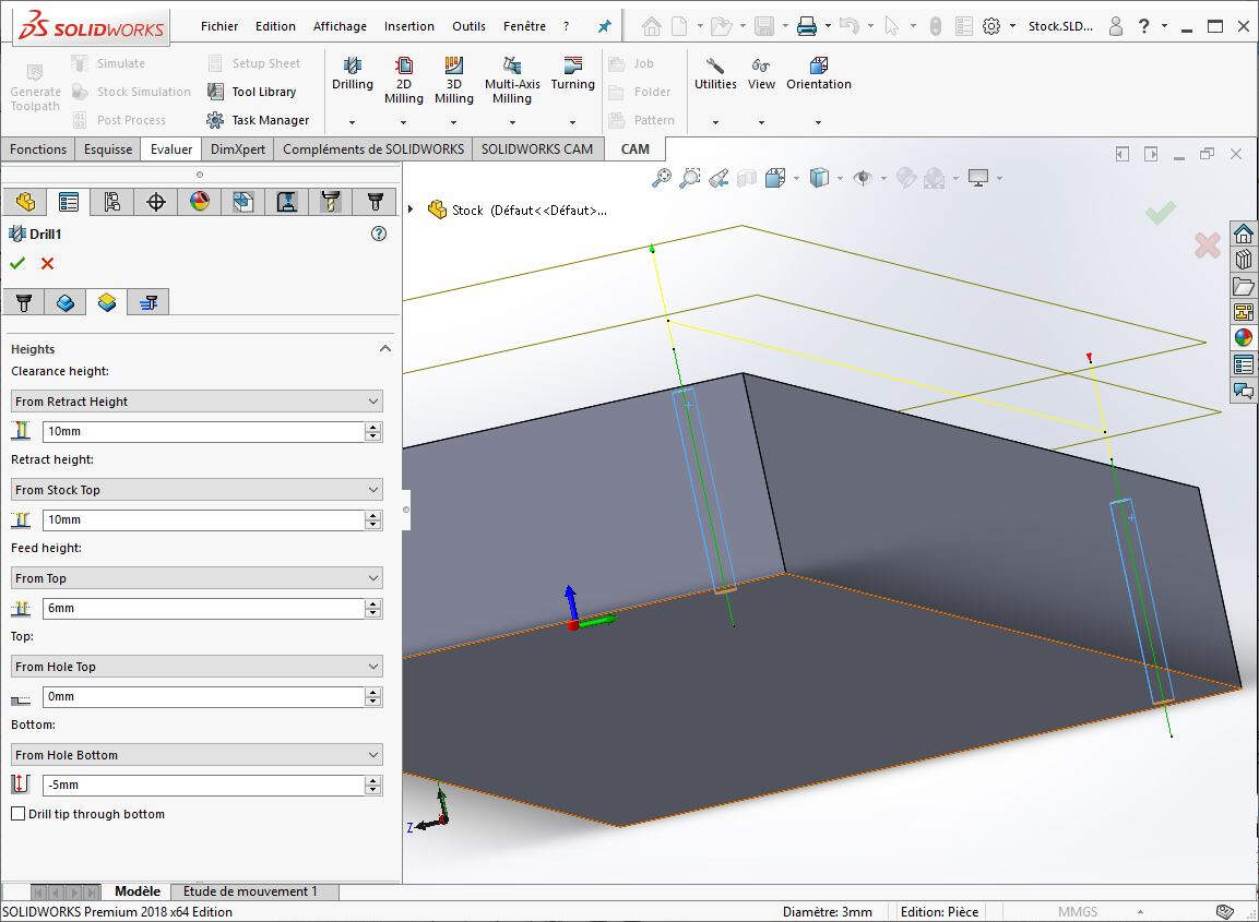
Then I generated the toolpaths for drilling the centering holes and cutting the edges of the stock.
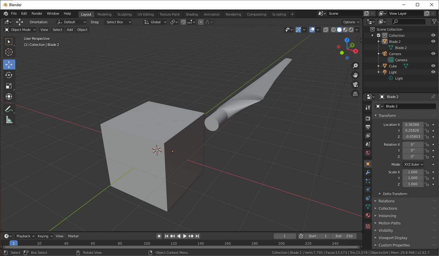
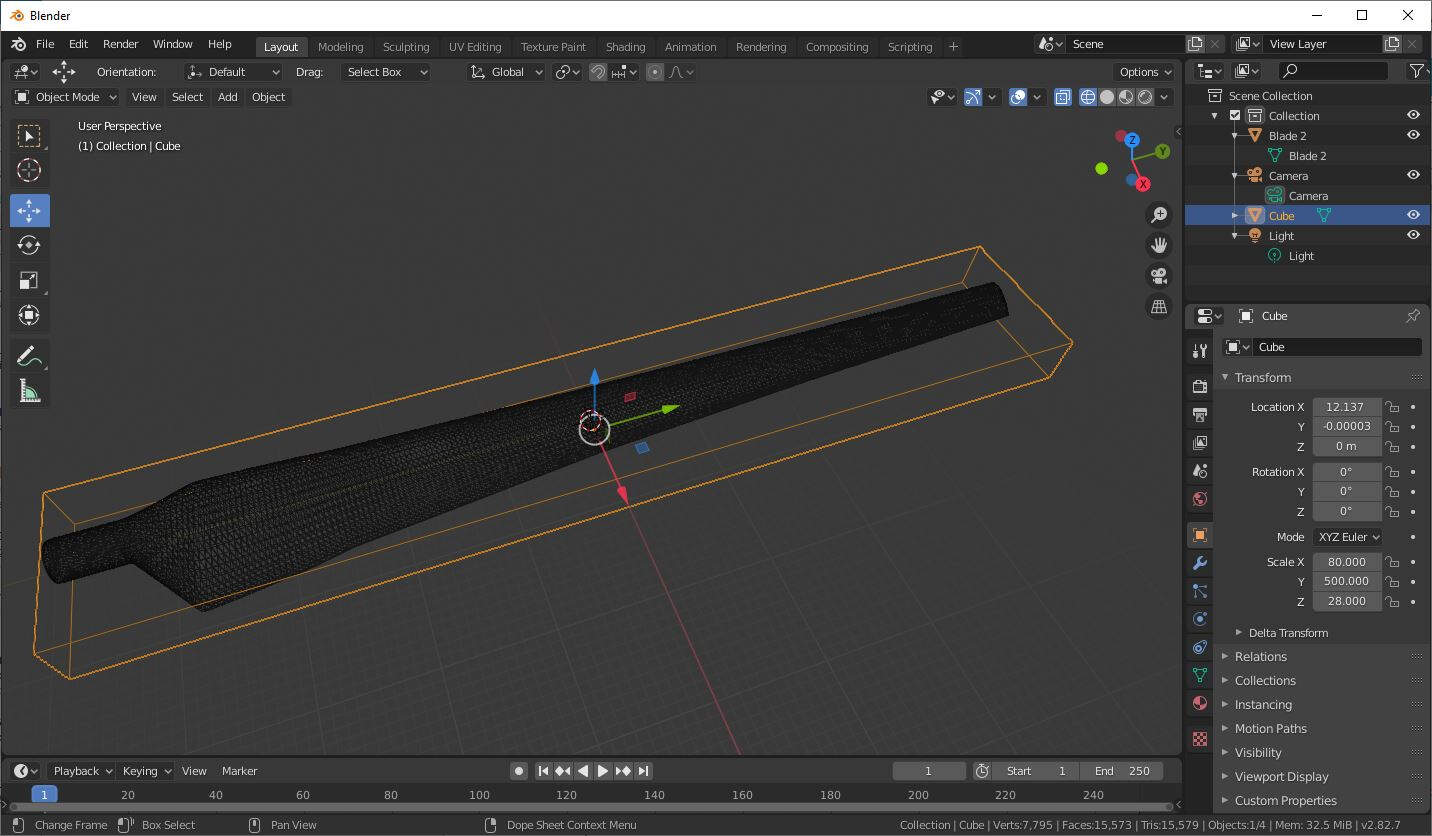
The problem with this whole cutting strategy would be that at one moment the blade would be separated from the stock and wouldn't be attached to anything while milling it. To solve that issue I also draw a negative of the blade, a kind of a mold, to maintain the blade stuck to the milling machine ground. To do this, I used Boolean modifiers in Blender to keep the difference between a cube and the blade.
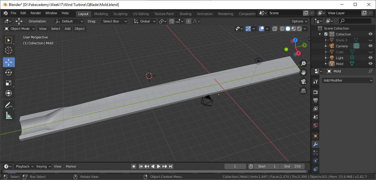
If this is not clear you will probably understand in the next section.
Mill Manufacturing Process
First I milled the first side of the blade in a building foam block. I made a first cut with a 3mm Flat end mill.
.jpg)
Then I made a finishing cut with a 1mm Flat end mill.
.jpg)
Here is a closer look to the finishing cut.
.jpg)
After a little bit of cleaning here is the first milled side.
.jpg)
Then I cut the edges and drilled the centering holes.
.jpg)
Now it can be removed from the milling machine.
.jpg)
Then I cut the mold that will maintain the blade against the milling bed.
.jpg)
Once gain I first used a 3mm Flat end mill for a rough cut then a 1mm Flat end mill for the finishing cut.
.jpg)
Then I put double sided tape on the blade.
.jpg)
And I pasted it on the mold. I added an extra layer of wood to make it more or less the same size of the original stock.
.jpg)
Then I fixed the whole parts on the machine bed with screws and I used the centering holes to make sure that the stock work coordinate system of the stock is aligned with the one parametrized earlier.
.jpg)
Once again I used a 3mm Flat end mill to make a rough cut.
.jpg)
Here is the rough cut result after cleaning.
.jpg)
Then I made a finishing cut with a 1mm Flat end mill.
.jpg)
By removing the blade from its support I accidentally broke the blade. So I used tape to put the two half blades together. I also used sandpaper to clean some foam residuals.
.jpg)
This is the finished foam core of my blade.
.jpg)
It is time now to cut the fabric that will surround it.
ExactFlat Online
To cut the fabric I planned to use a laser cuter machine. To generate the exact flatten shapes that would be cut out from the cotton fabric I used ExactFlat Online. The reader will see that I went through the whole process to create the flatten shapes. Unfortunately, due to license expiration, I was not able to save the generated files but it is still worth to have a look on the procedure. First I intuitively downloaded the STL file.
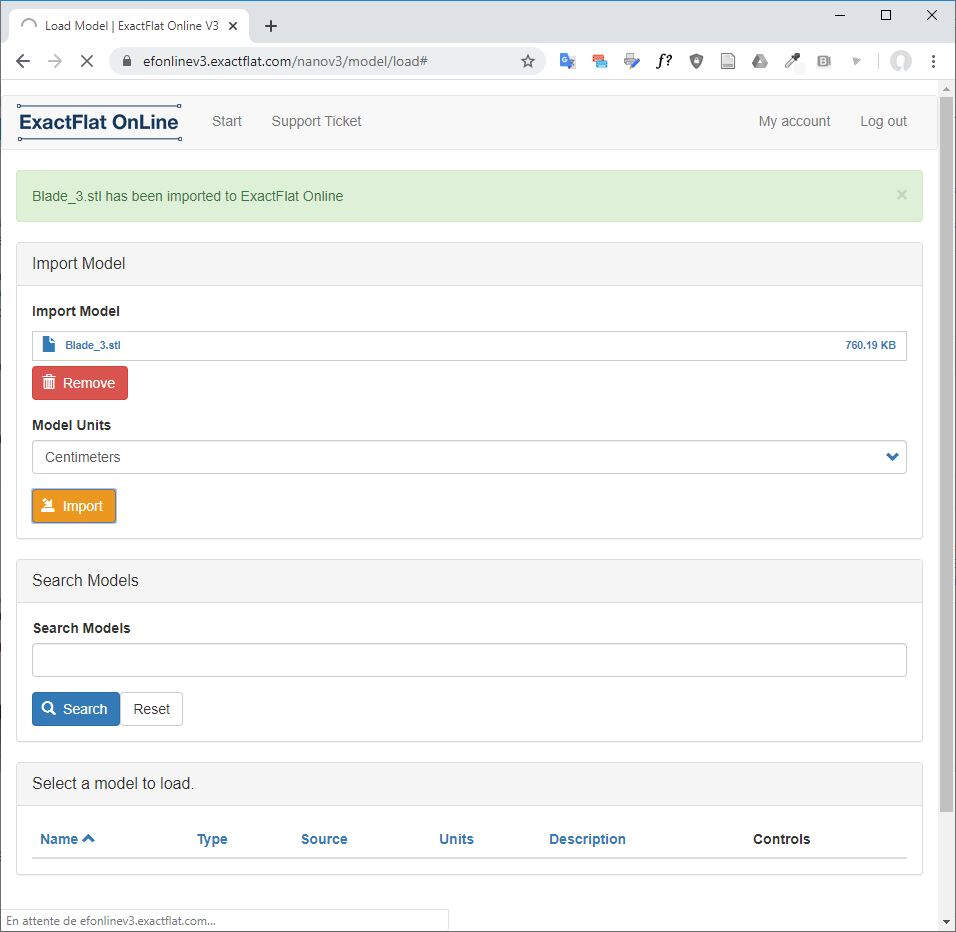
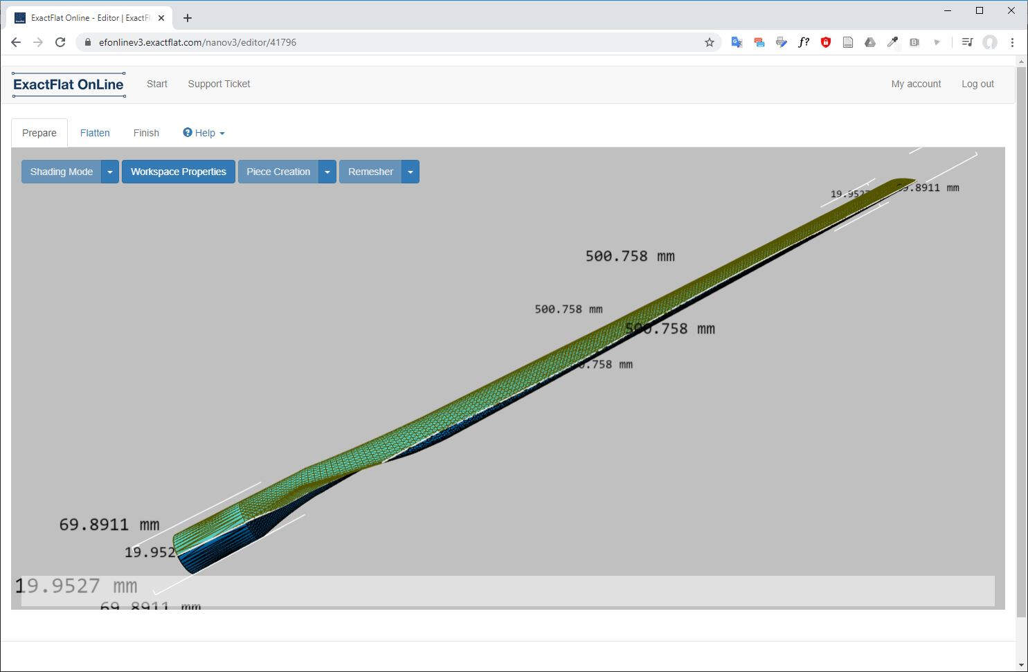
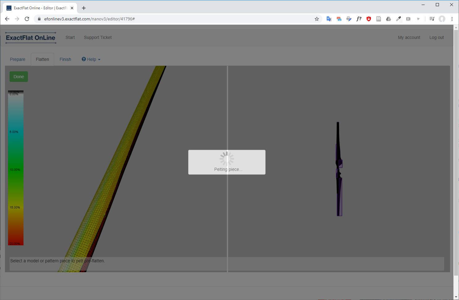
After loading, I arrived to that page.
In the Flatten tab there is a series of tools that can be used to flatten the 3D model.
But as I was intuitively trying with the tools I got a pretty ugly result at the end.
I recommend to anybody to first have a look on the ExactFlat Online Help Video Series. I found this link in the Help tab of ExactFlat Online.
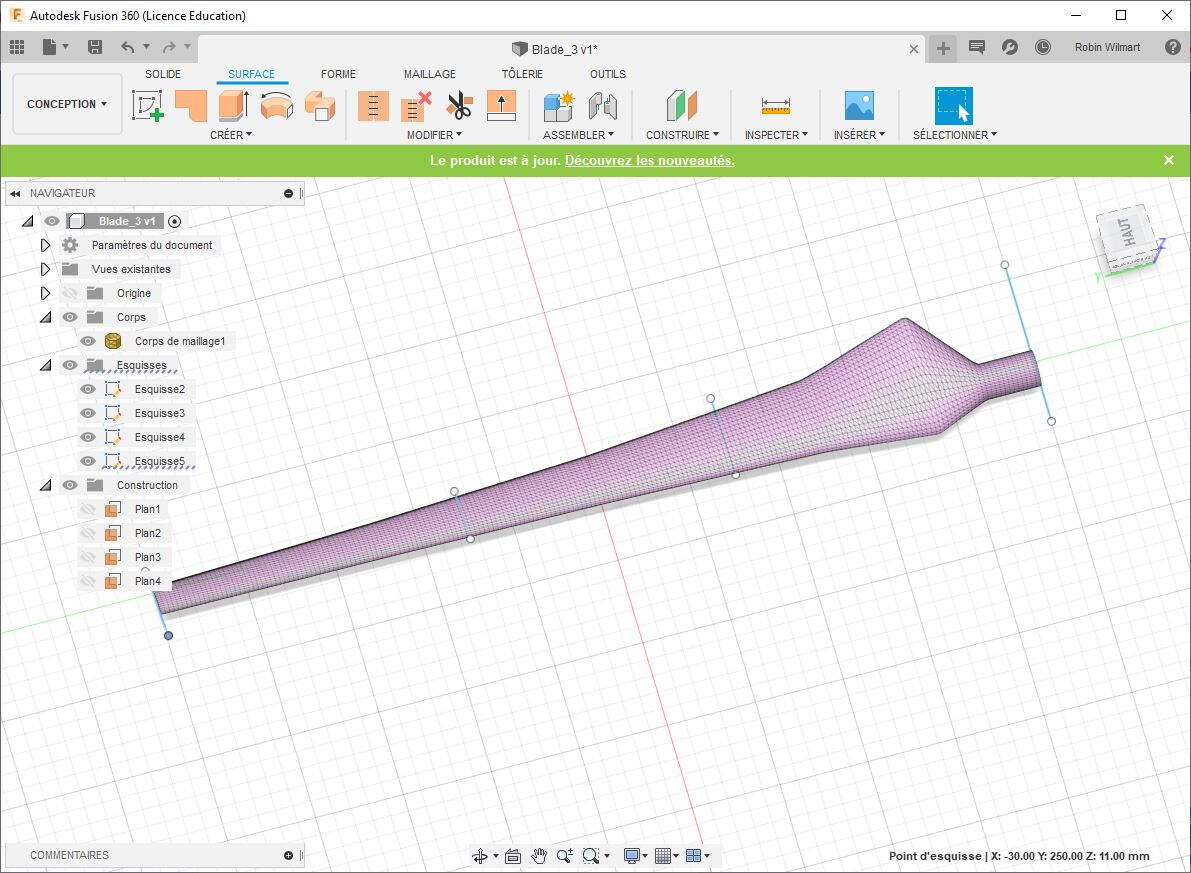
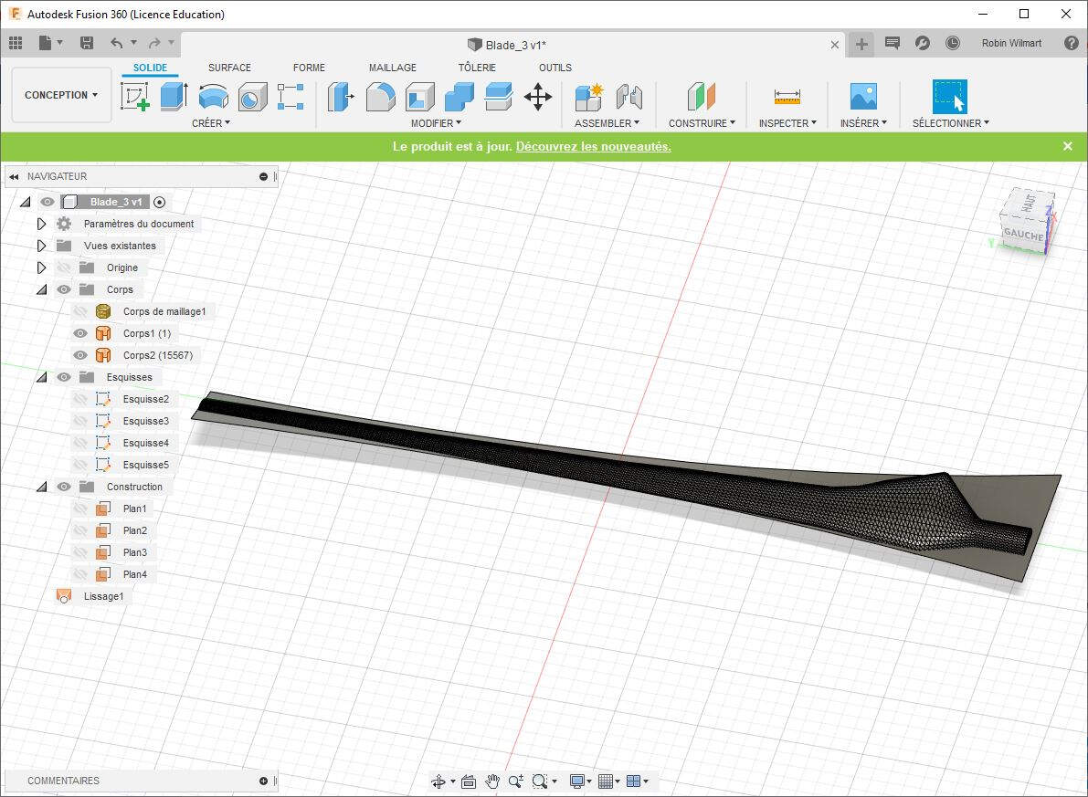
In the first video they explain that most of the job must be first done in a CAD software to create two separate open surfaces. To prepare the 3D model I used Fusion 360. I looked at this tutorial to know how to split body into two parts. First I drew four lines each in a different plane.
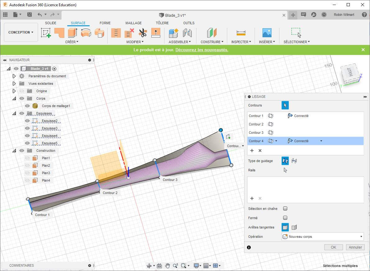
Then I used the Loft feature of Fusion 360 to draw a cutting surface.
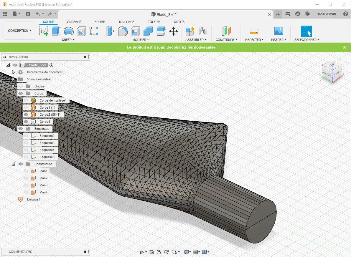
To be able to cut the solid into two parts according to the cutting surface I first needed to make the mesh object solid. To do it I followed this tutorial. As proposed I clicked on Modify (SOLID TAB) -> Mesh -> Mesh to BRep, I selected the mesh object and I clicked OK.
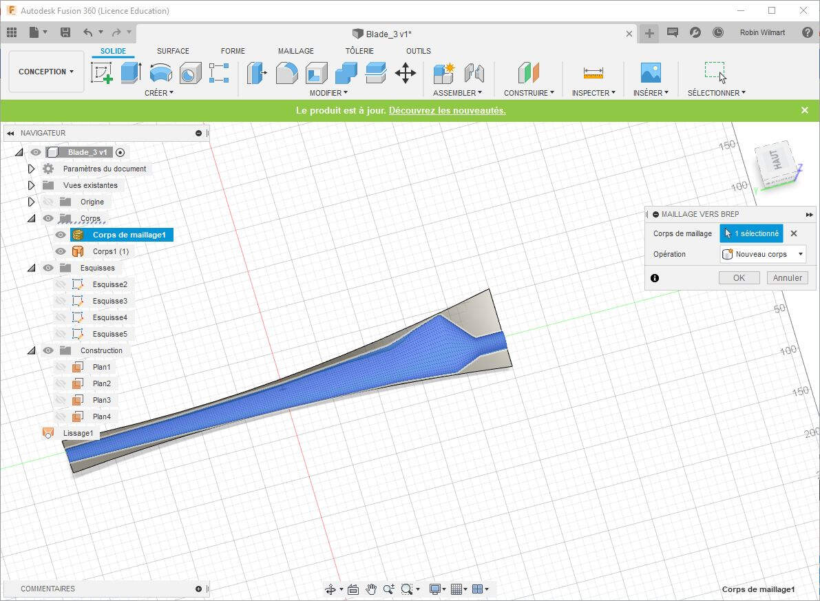
Here is the result.
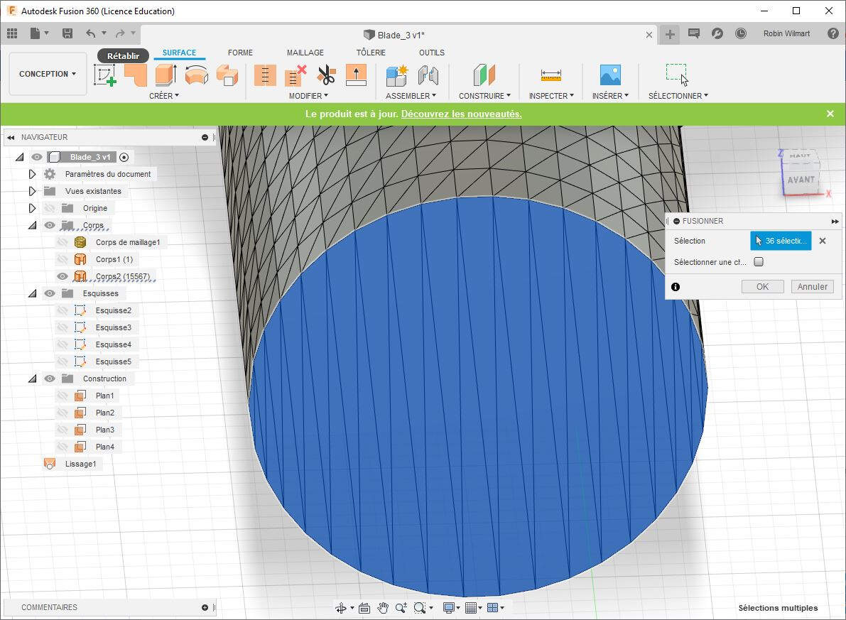
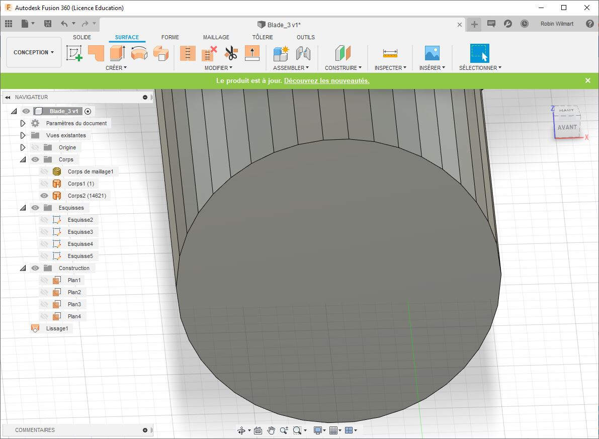
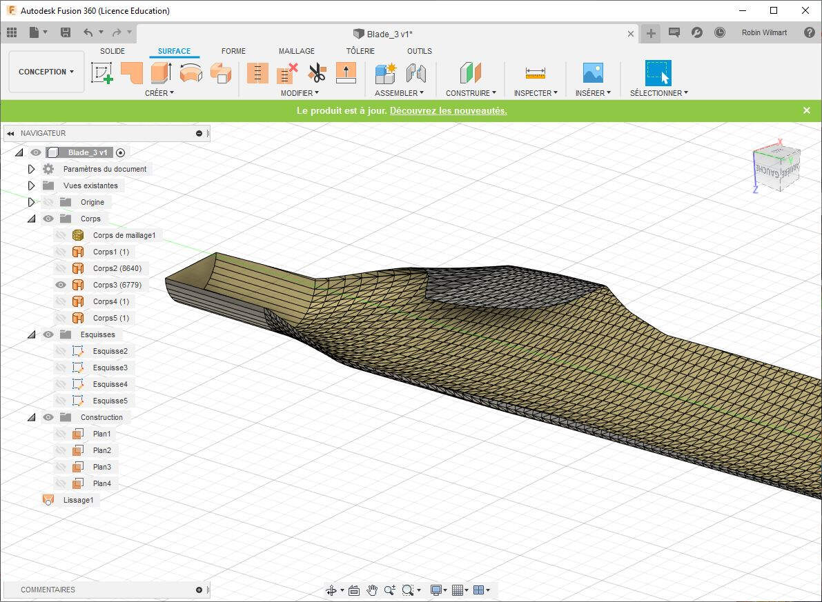
Also, before cutting the solid into two parts I merged the faces selected in the picture below by clicking Modify (SURFACE TAB) -> Merge and hitting OK.
It is much better like this, isn't it?
To slip the body into two parts I selected Modify (SOLID TAB) -> Split Body.
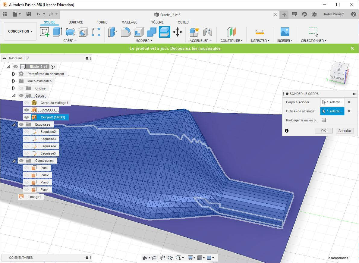
Here is the result.
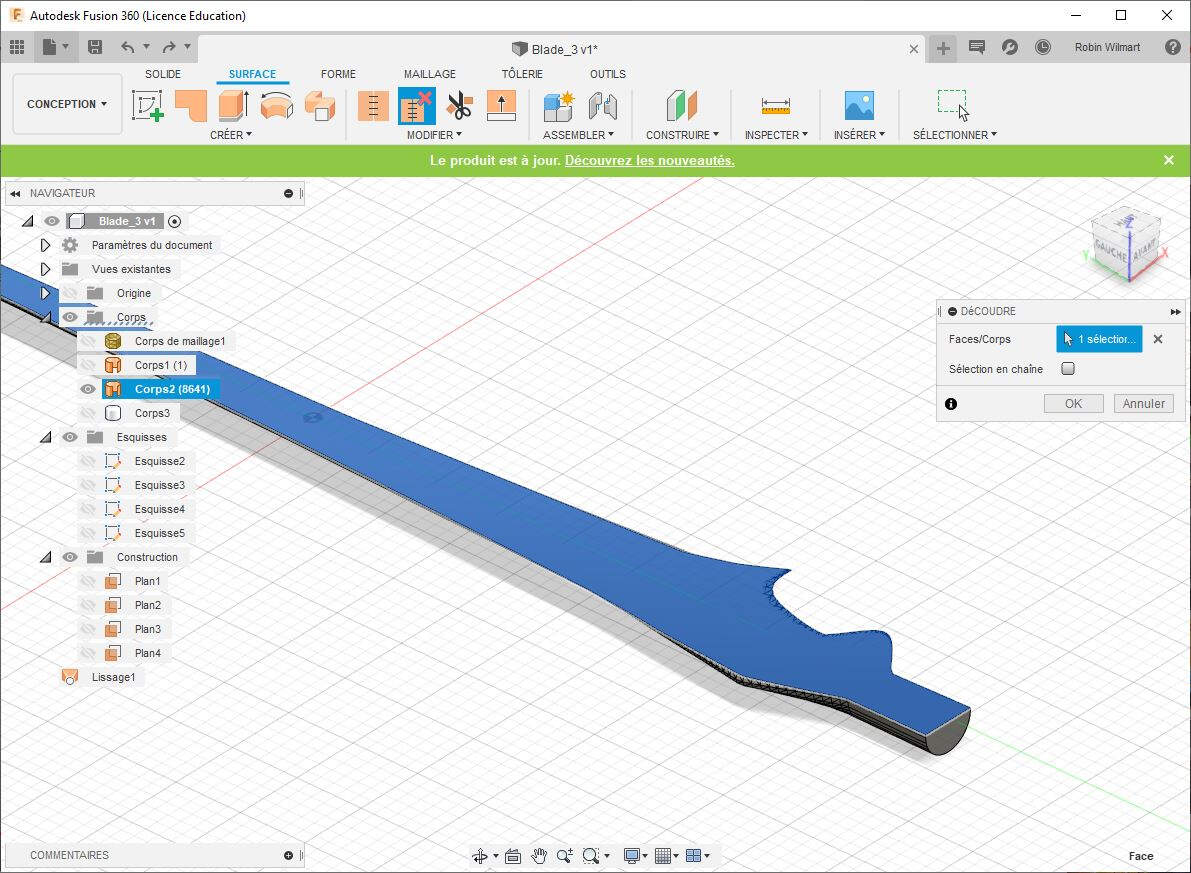
Now ExactFlat needs a file with surfaces and not solids. To do that I should simply remove the surface selected below. It is not that easy. I followed this video to manage it. I first selected the blue surface then I went to the surface tab and I clicked on Modify -> Unstitch. I made sure that the checkbox Chain Selection was unticked and I clicked OK.
Now I have two separated surface.
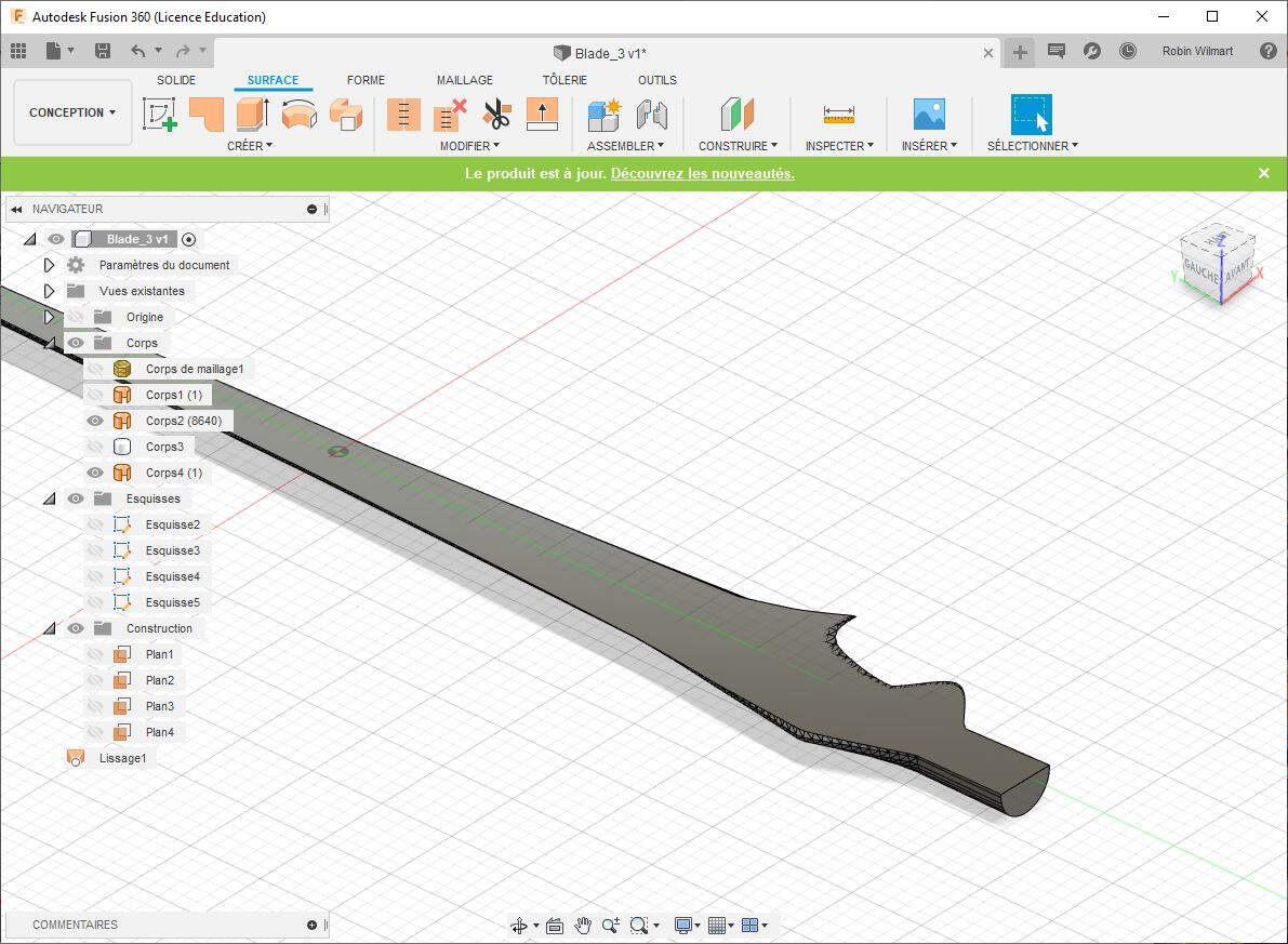
I made the same for the upper part and I deleted all the unnecessary bodies.
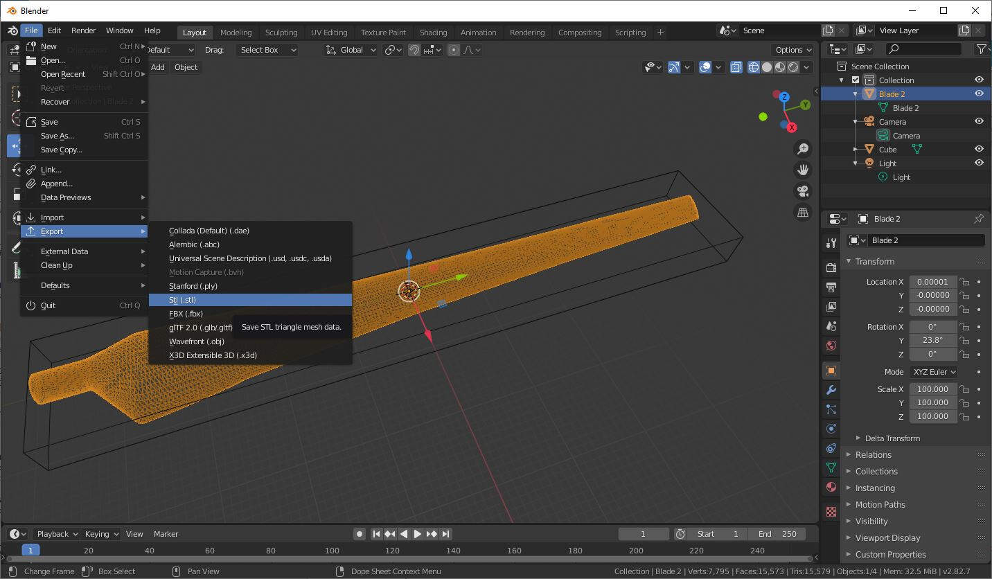
Finally I exported the result as an OBJ file.
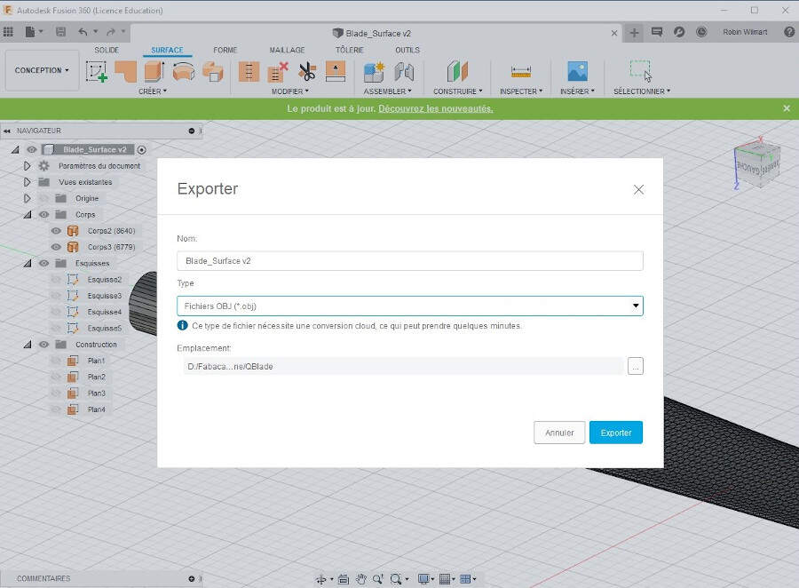
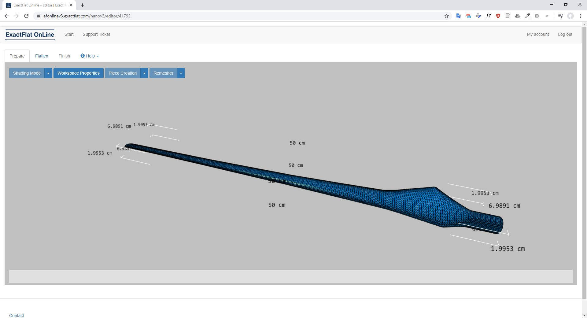
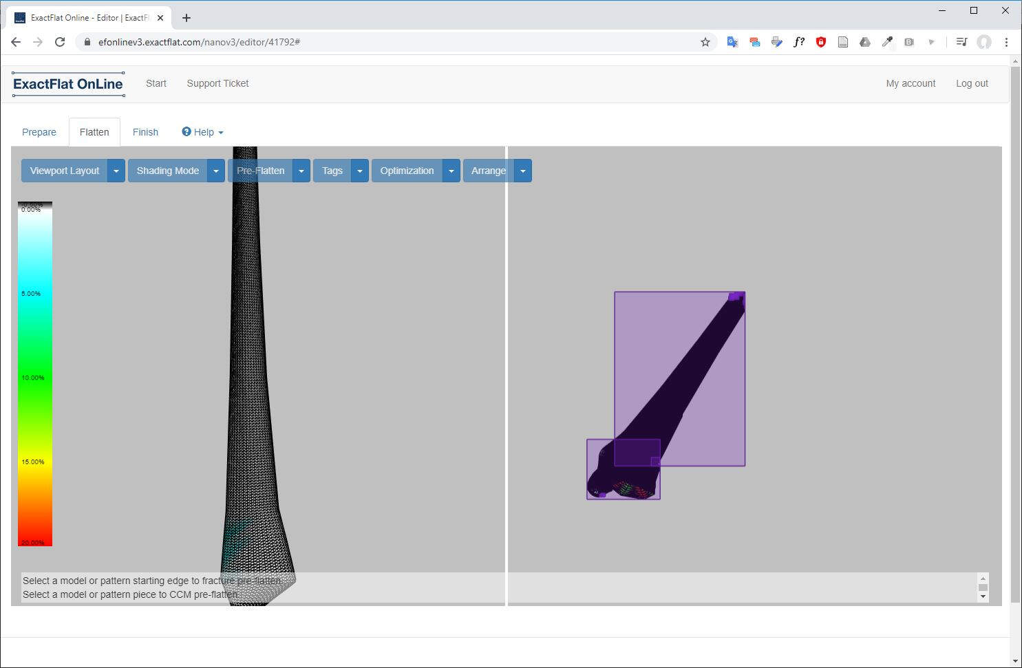
Then I imported this file in ExactFlat Online.
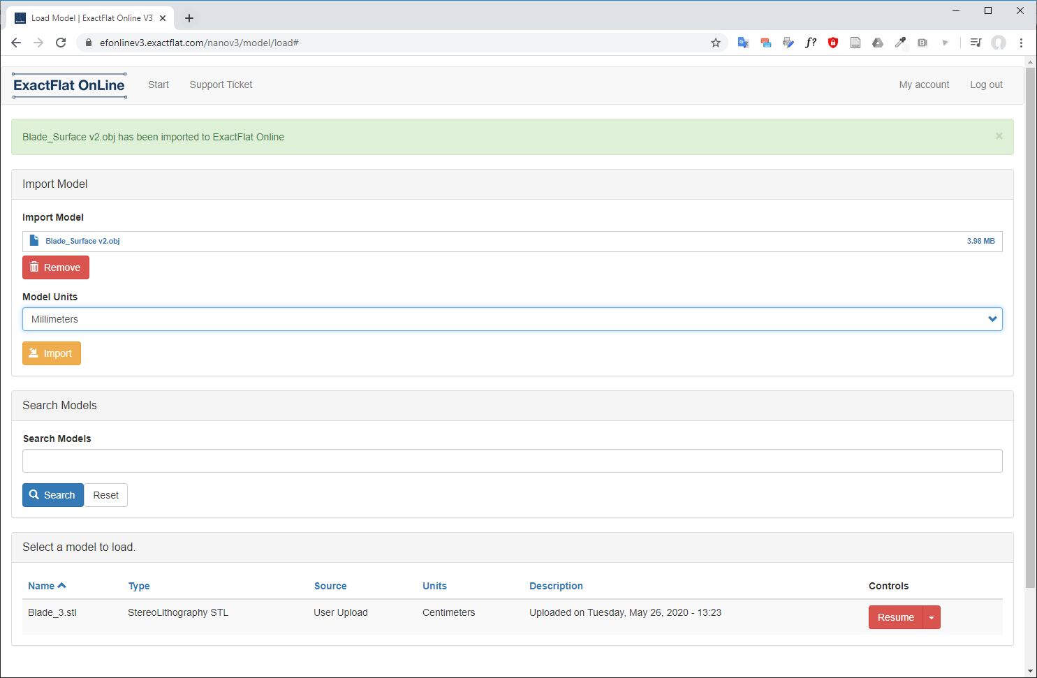
Now we can clearly see that there are two parts, two separated surfaces.
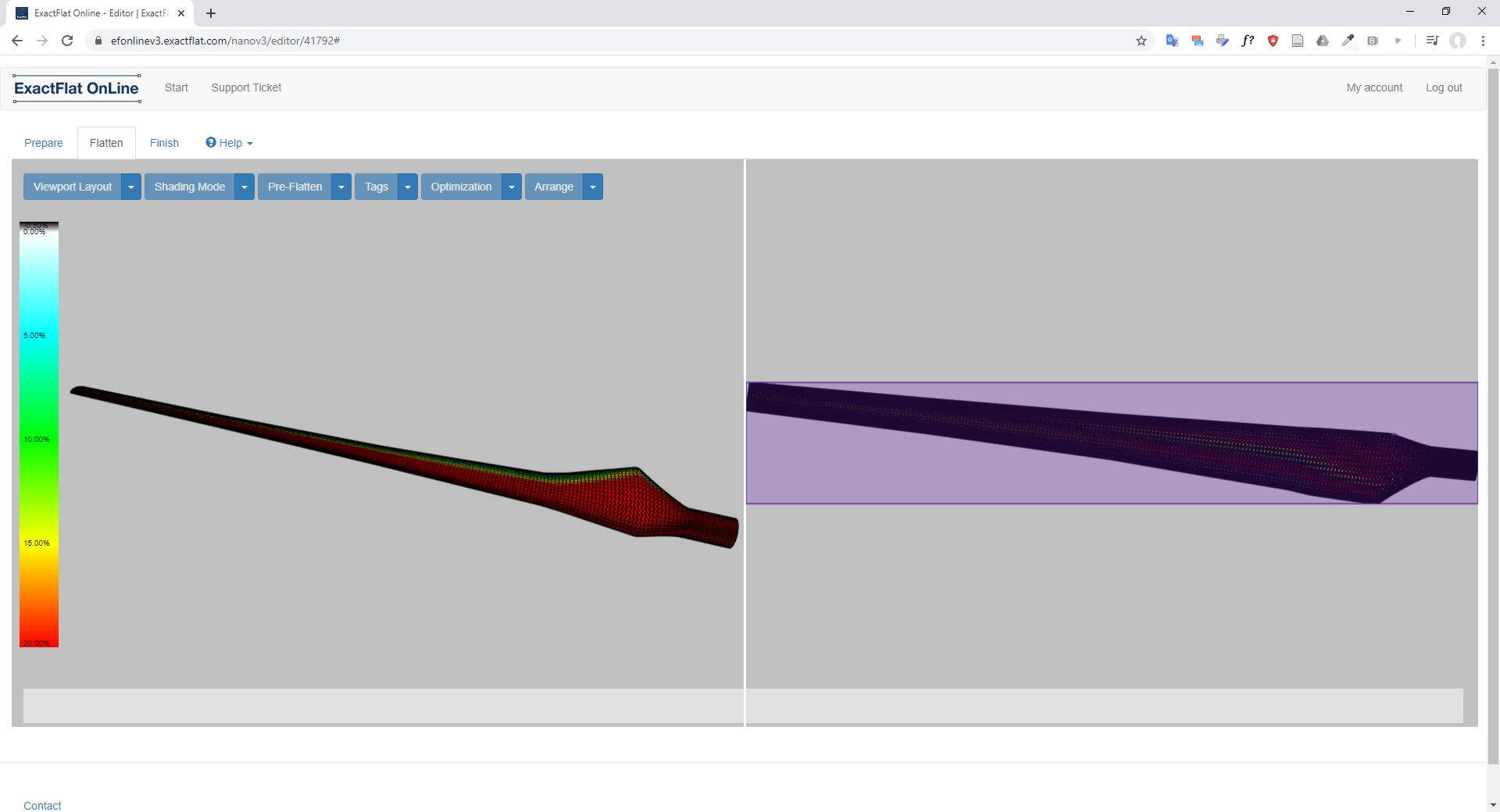
I selected both surfaces and I clicked on Flatten.
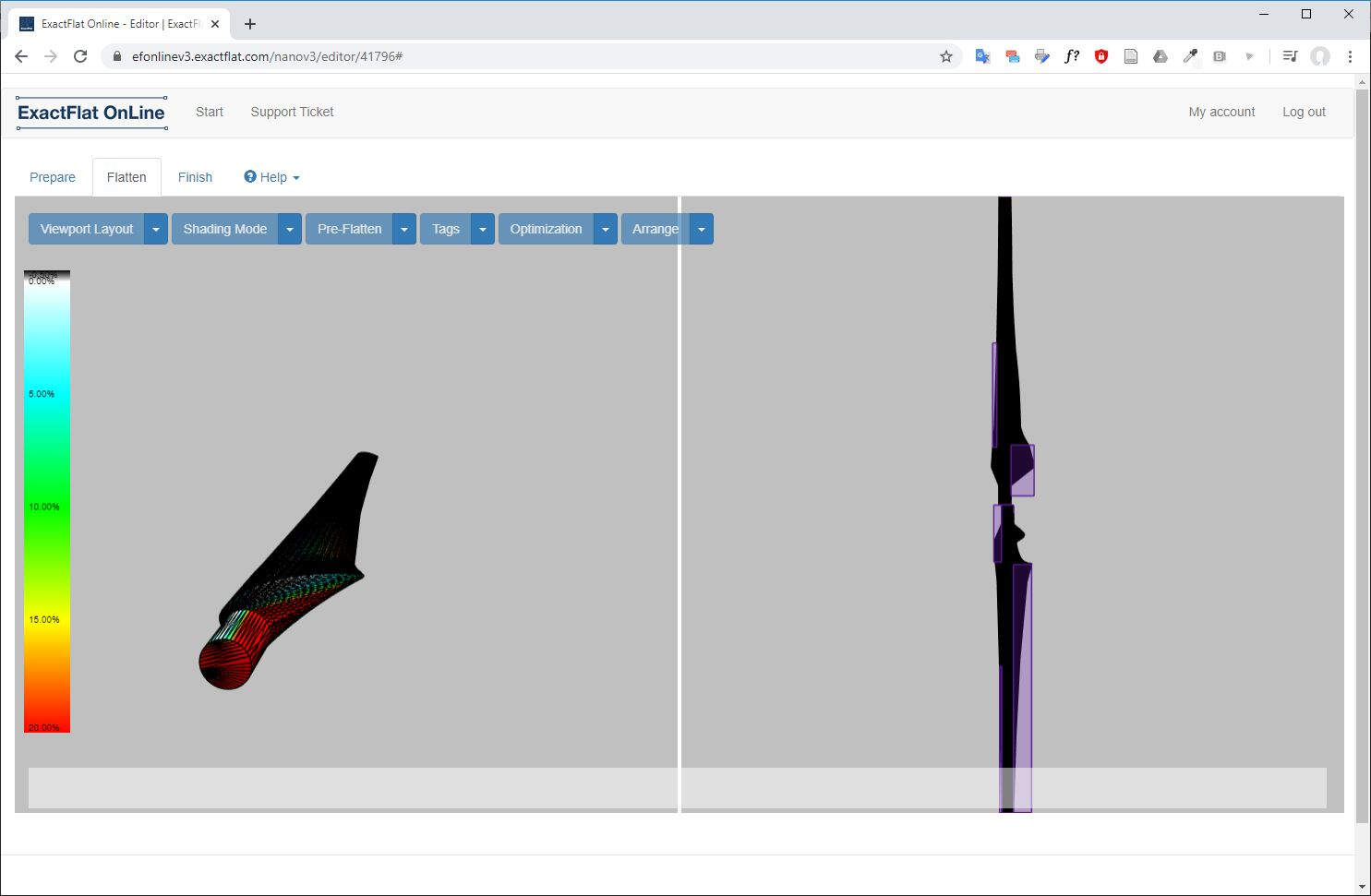
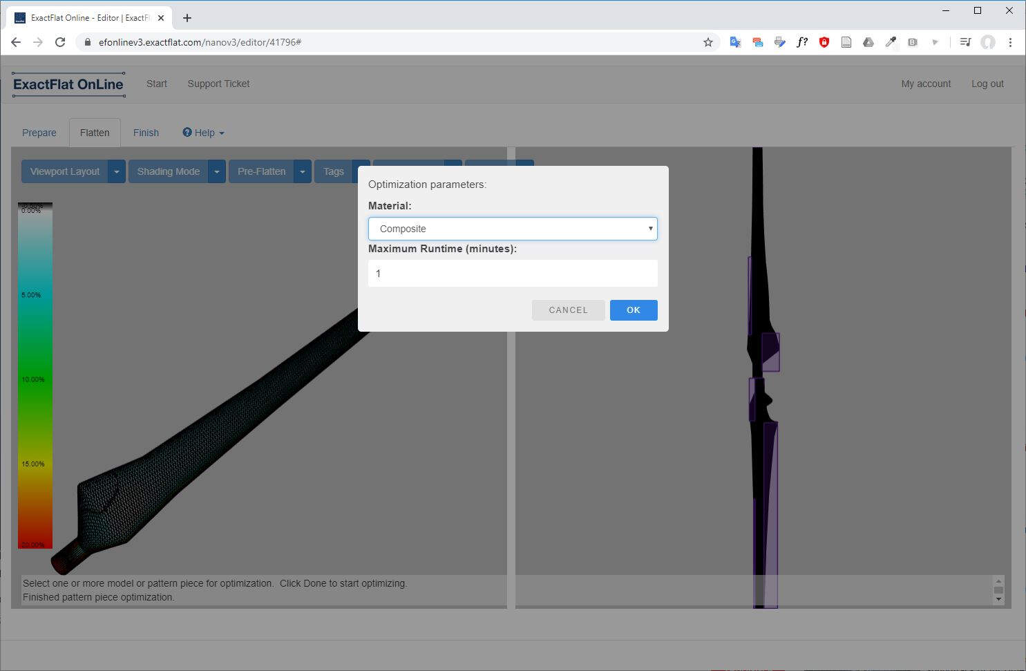
Then in the Pre-Flatten tab I selected Pelt option which is more adequate for rounded shapes.
I also used the Optimization option where I selected the material and I clicked OK.
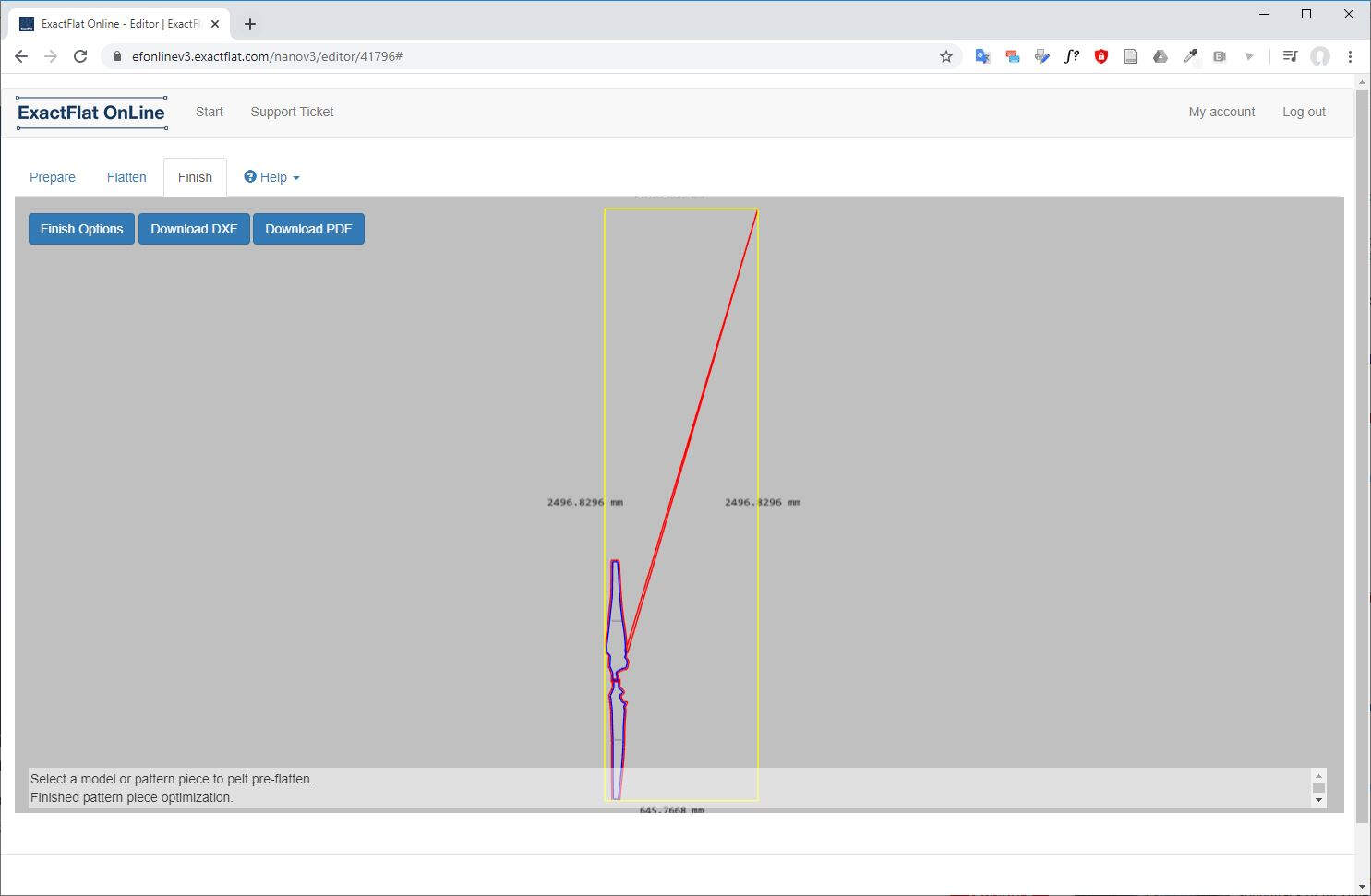
After optimization ended I clicked on Finish and I arrived to that page.
Unfortunately when I tried to generate the DXF files I got an error to license expiration.
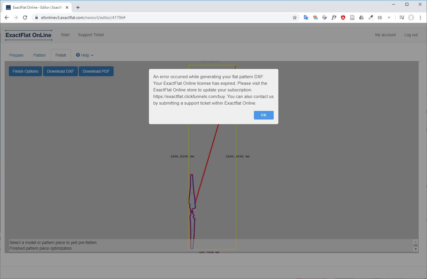
As a consequence I planned to cut the fabric in the old fashion way, with scissors.
Composite fabrication process
As I was not able to generate the DXL files to cut the cotton due to license validation, I decided to cut the cotton fabric in the old fashion way, with scissors.
.jpg)
.jpg)
Then here is the material I prepared for the manufacturing process: a vacuum bag, a plastic bag to keep the vacuum bag clean.
.jpg)
Then I prepared the epoxy. I chose the IN2 Epoxy Infusion Resin. First I checked the datasheet of the product on www.easycomposites.co.uk as strongly suggested on the product container label. To prepare it I had to mix IN2 Epoxy Laminating Resin with the AT30 FAST hardener. Hardener at a ratio of 100 parts of resin to 30 part hardener, by weight. As a consequence I made a first test by mixing 10g of resin to 3g of hardener.
.jpg)
Then I poured the mixing of a small square of cotton that I pressed around a small block of foam.
.jpg)
Because of lack of time I decided to go forwards without waiting for testing results. I mixed 50g of resin with 15g of hardener. I soaked both cotton pieces and I placed them on the blade foam core. I covered it with the plastic bag then I placed everything in the vacuum bag.
.jpg)
I vacuumed the bag.
.jpg)
Everything seems in good place.
.jpg)
Strangely this time the resin inside the cup hardened in only 15 minutes while the resin in the first test cup was still not hardened.
.jpg)
12 hours later I removed the blade from the vacuum bag.
.jpg)
I cut the edges.
.jpg)
And here is the final result.
.jpg)
.jpg)
As you can see that I poured too much epoxy on the blade core and there are surface defects.
.jpg)
In the next section I'll explain what could be the possible solutions to improve the manufacturing process.
Improvements of the manufacturing process
First what would have greatly improved the final result would have to digitally cut the fabric. Then, as it can be seen upper, I put too much epoxy on the fabric by fear that it would not harden if there was not enough. I think that using less epoxy would improve the surface state of the blade. Finally, if I had had time I would have used two molds to compress the blade into shape while the epoxy cures. I also feared that the blade would stick to the molds, that's why I didn't try as a first try with epoxy but now I know that if I put a plastic layer between the fabric and the mold, the blade should not paste to the mold after the epoxy curing.