Week 16 - Molding and Casting
FAB ACADEMY 2020 source
20200513 molding from Academany on Vimeo.
My Assignment
This week assignment was about designing a mold around the stock and tooling then milling it (rough cut + (at least) three-axis finish cut) and using it to cast parts. To answer these requests I decided to cast a small human head replica. I was particularly interested in milling an object that would have been 3D sculpted by computer with a CAD software such as Blender.
Please follow this link to know about the group assignment.
Creation of the object
In this section I will explain how I created the head with Blender and how I fixed the head mesh with Meshmixer.
Blender
Since I'm not a specialist of Blender and I have very few skills in sculpting 3D models, I first looked for a Blender add-on that could help me in the task of creating a human head. I found MakeHuman, an open source application to generate and customize characters. I imported it in Blender and I customized my own character.
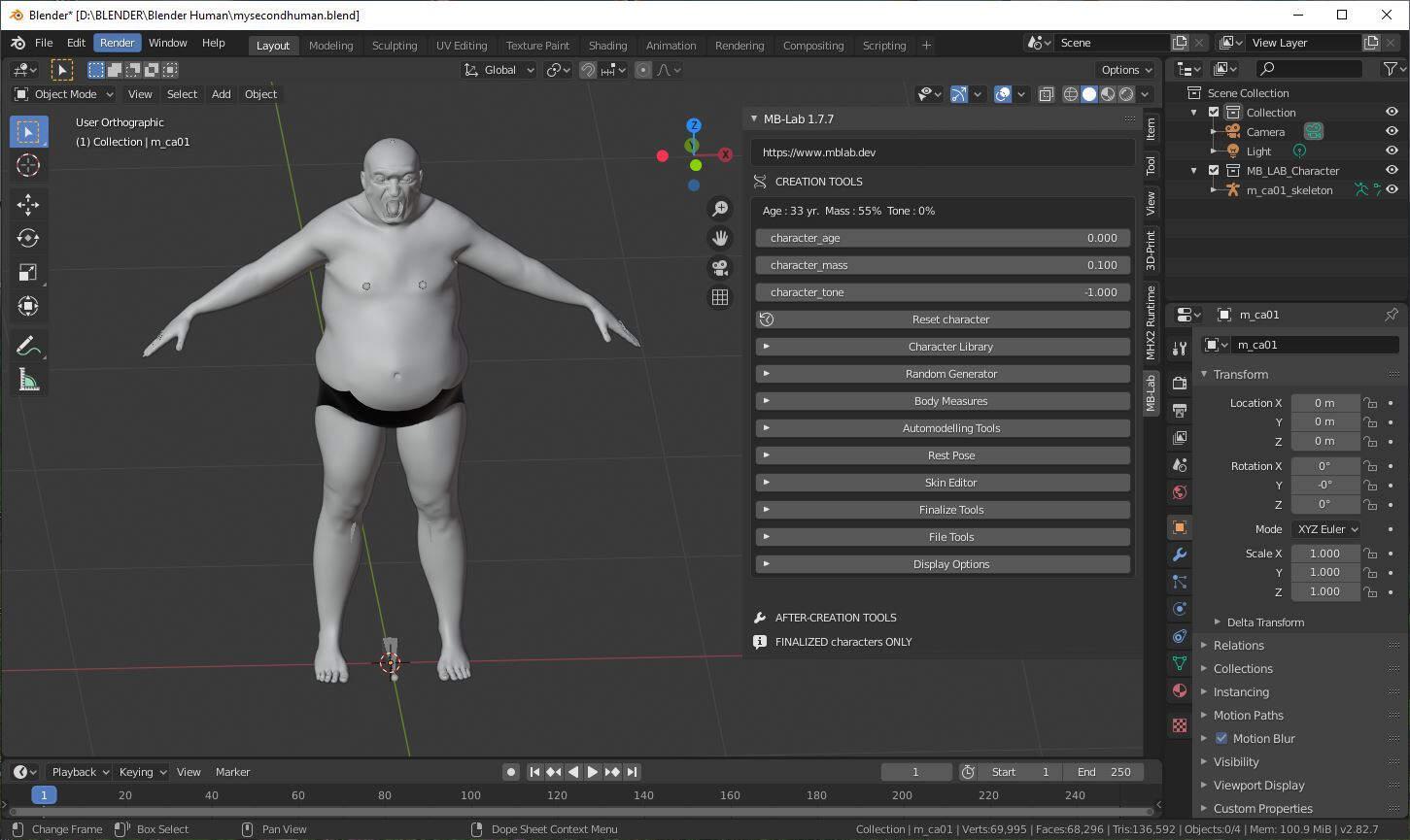
As the MakeHuman object had too much features such as a skeleton or other stuffs that I would not have use the purpose of this work I exported it as a STL file.
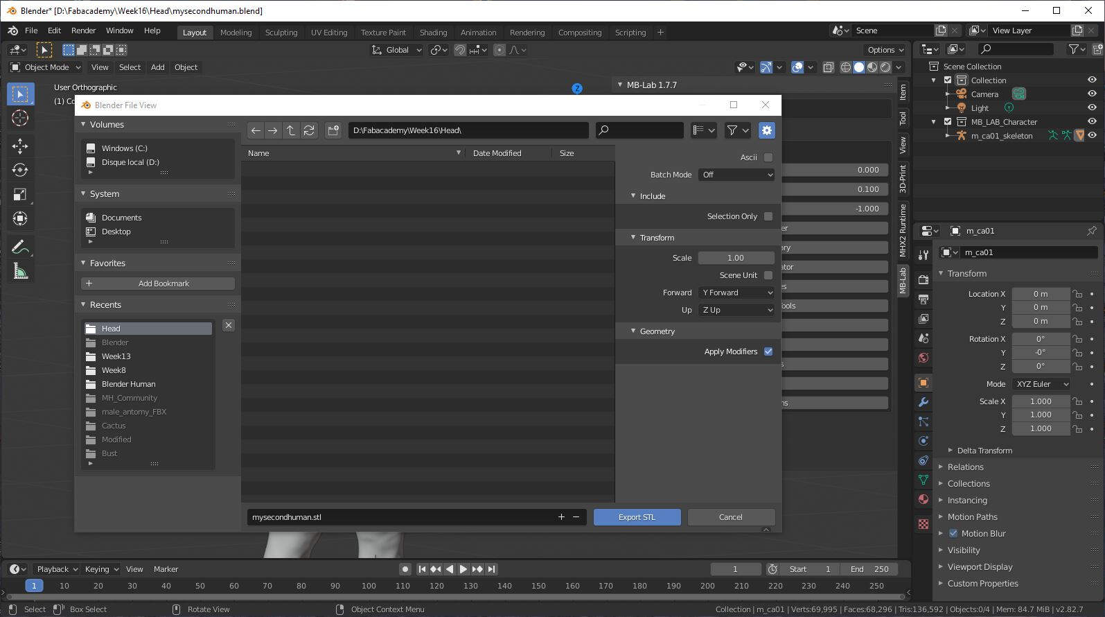
In the picture bellow you can see the newly created STL file.
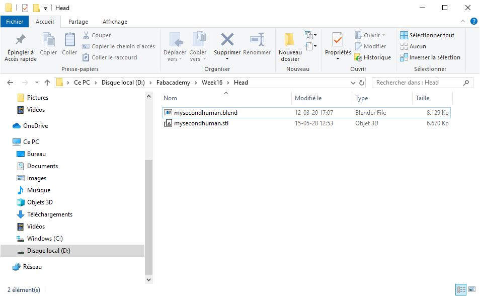
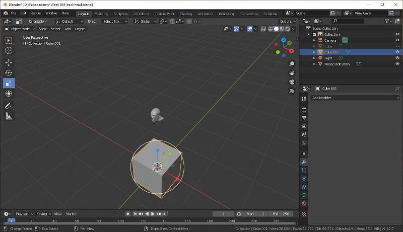
Then I created a new blender file in which I imported the STL file.
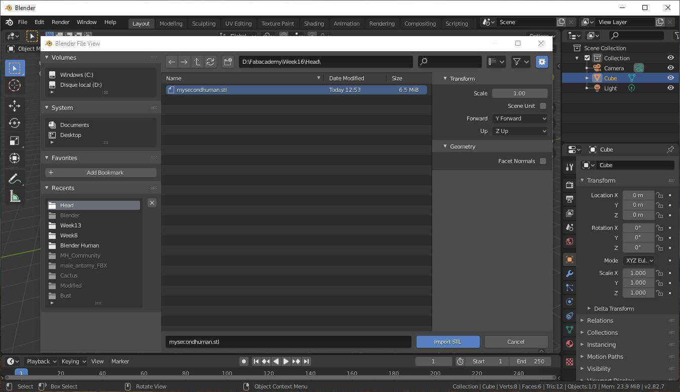
By typing Shift +A and selecting Mesh -> Cube I created a cube.
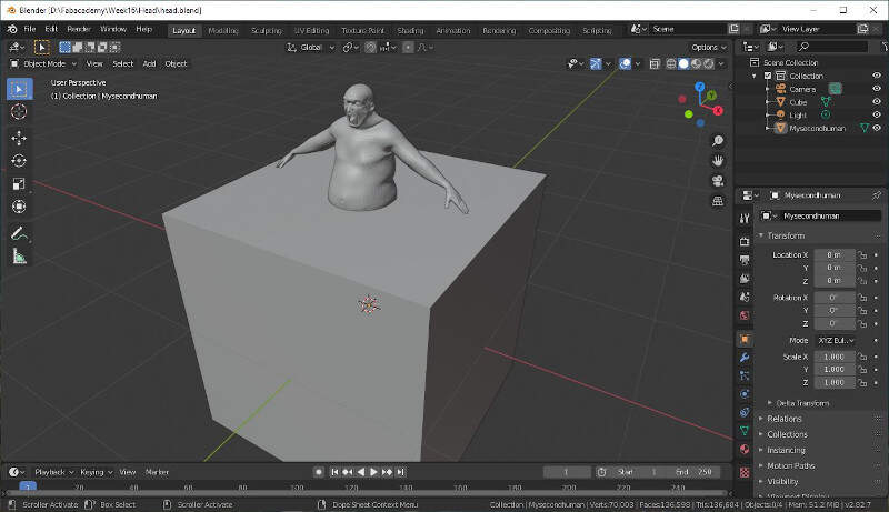
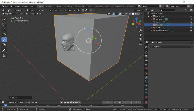
I used this cube to cut the head so I first placed it in such a way that it covered the whole character body.
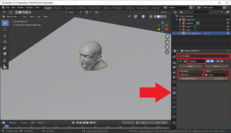
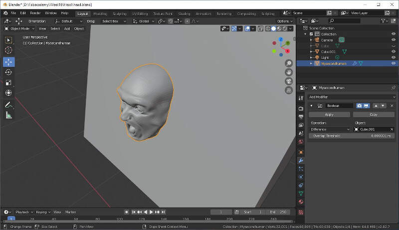
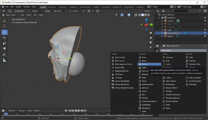
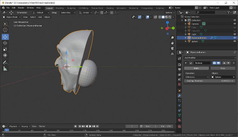
Then in the right side panel I applied a boolean modifier on Mysecondhuman object to make the difference with the cube.
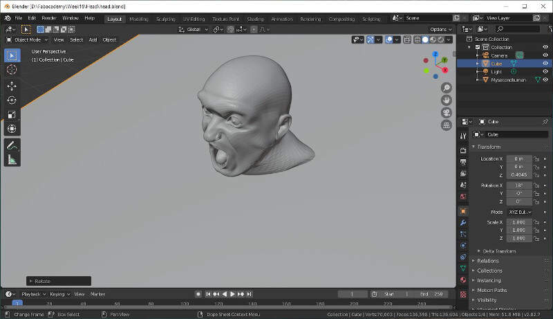
When the modifier is applied and that the cube is hidden only the head remains as a result.
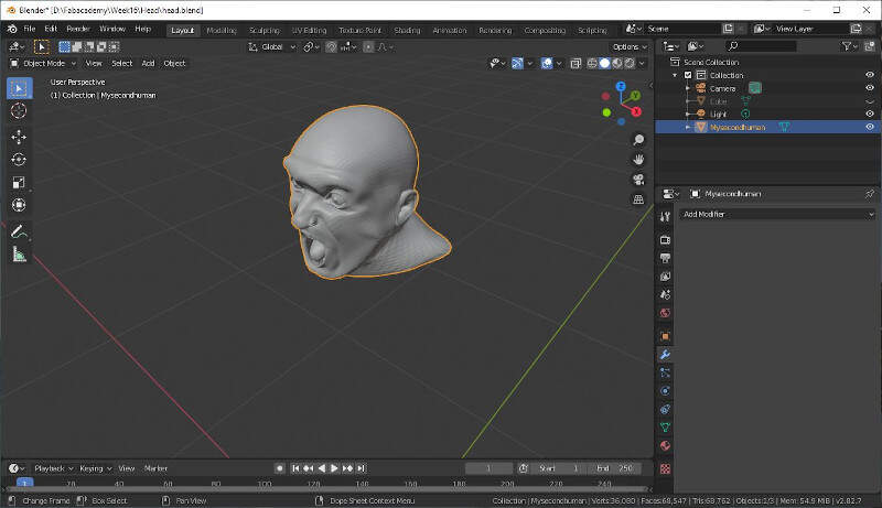
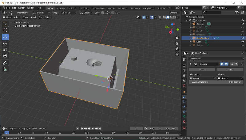
Then I added a new cube to remove the back of the head.
I scaled it and placed it at the right position.
Once more I added a boolean modifier to remove the back of the head.
Here is the result.
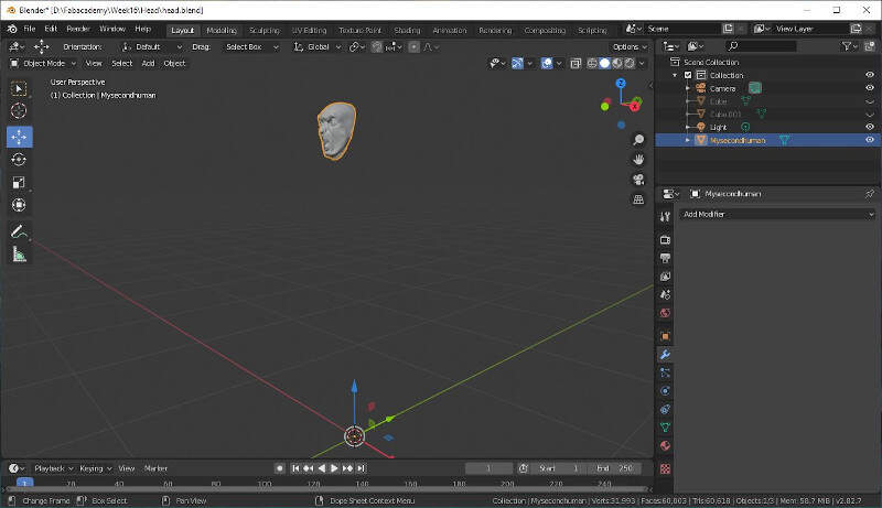
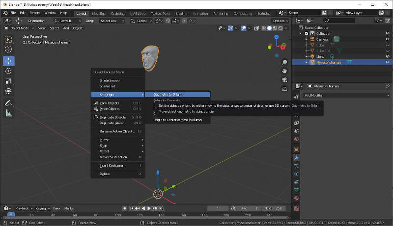
Then I move the remaining head to the origin of the frame by right clicking on the head and by selecting Set Origin -> Geometry to Origin.
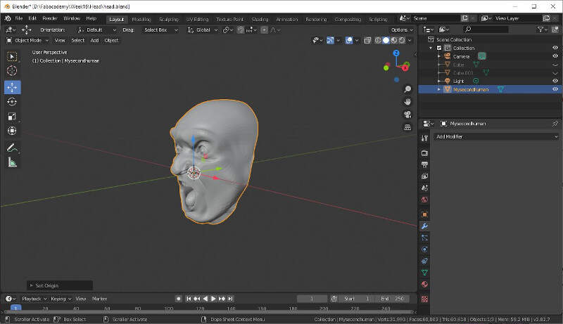
Here is the result.
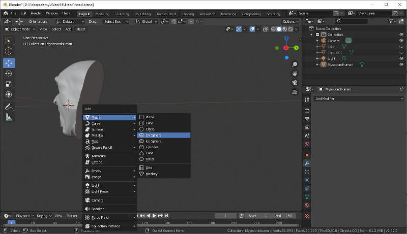
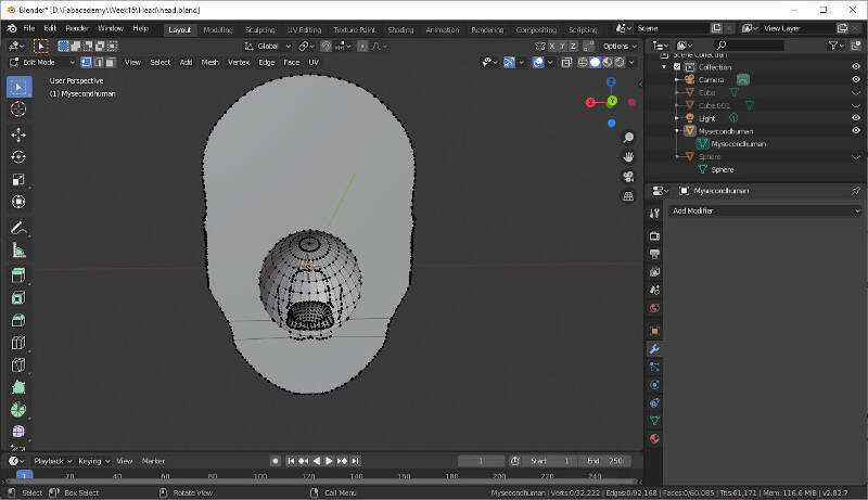
To make the inside of the mouth, I added a sphere.
I scaled it.
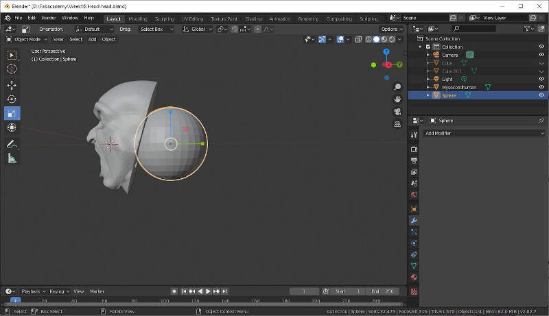
I made it an ellipsoid.
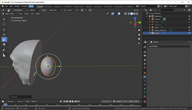
I placed it at the right place to make a hole.
Once again I applied a boolean modifier to keep the difference between the head and the ellipsoid.
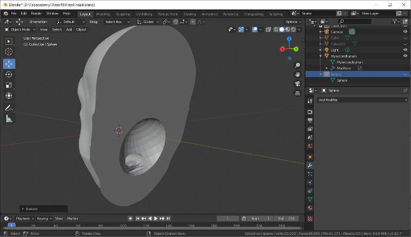
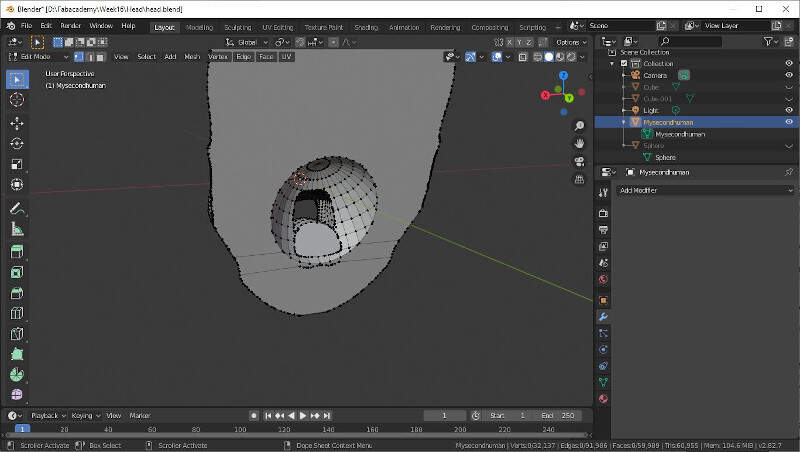
Thus in Edit Mode I modified the mesh.
I selected the faces I wanted to erase and I pressed delete and selected Faces.
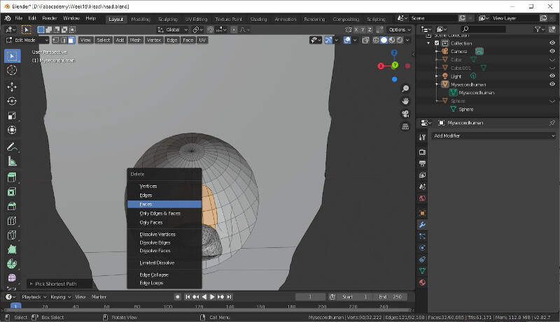
Now that's better.
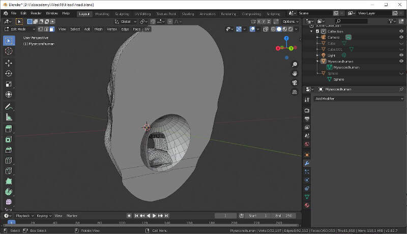
I still had to close the area at the back of the tong. To do that I selected a loop around the area that I had to close, I right-clicked and selected New Edge/Face from vertices.
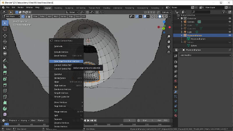
Now it's much better.
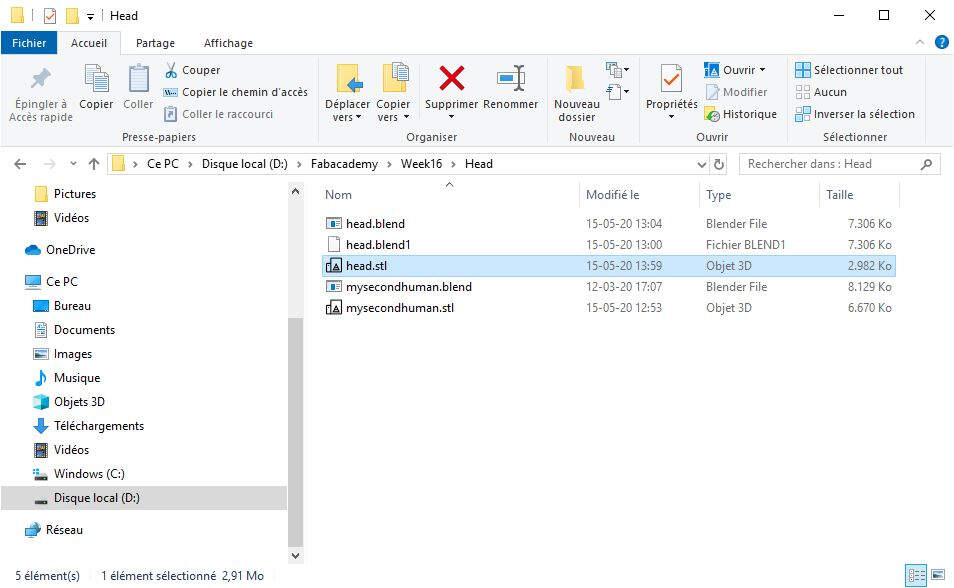
It was time to export the file as an STL file.
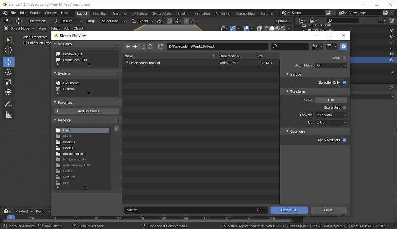
I called it head.STL.
It was time then to check if the mesh was good enough to be printed or milled. That's why I used Meshmixer.
Meshmixer
Meshmixer is very useful to clean up a 3D scan, do some 3D printing, or design an object that fits something else. It is free for Windows and macOS and can be downloaded here.
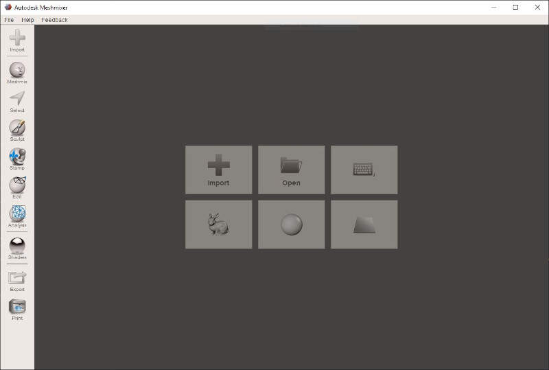
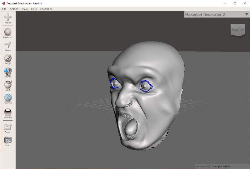
I imported the head.STL file.
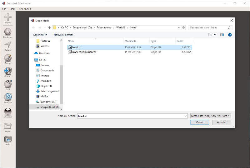
It was well imported.
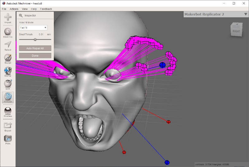
In the Analysis tab I click on Inspector and I got many errors. By clicking on the colored spheres Meshmixer tries to repair the error.
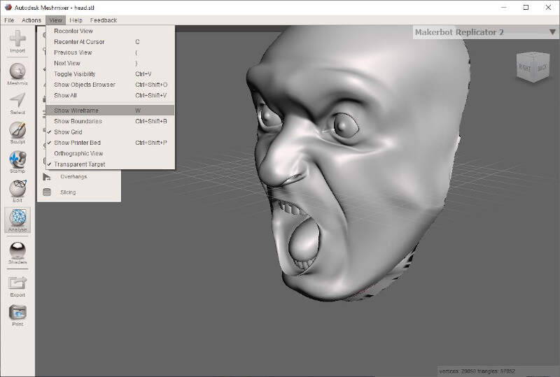
By clicking on W we can show the Wireframe.
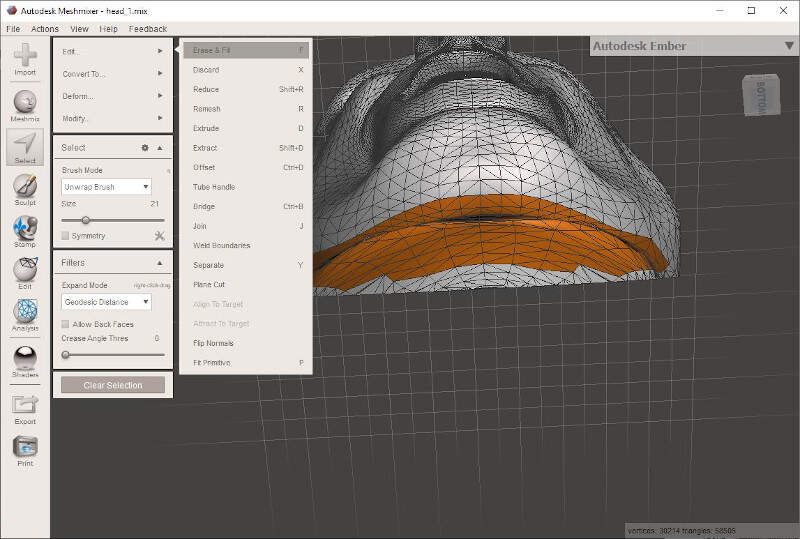
To have a clean cut at the back of the head, it is possible to use the function Plane Cut in the Edit tab.

I also cleaned the neck of the character since this area would not be reachable by the the milling machine.
Finally I exported the head once again as a STL file.
Design of a high density polyurethane mold
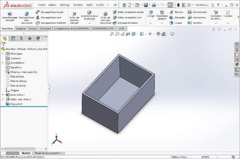
To make my first mold I had a 250x250x50mm block of High Density Polyurethane Foam at my disposal. I used SolidWorks to precisely design my mold container, a box of approximately 100x70x50mm.
Solidworks
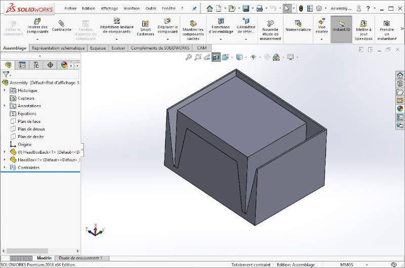
I made a first box for the head.
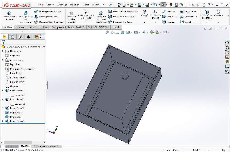
Then I made a second box for the troat.
In an assembly file I checked that both part fit to each other.
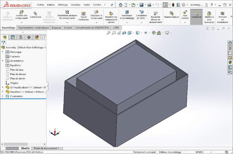
To do that I cut the assembly.
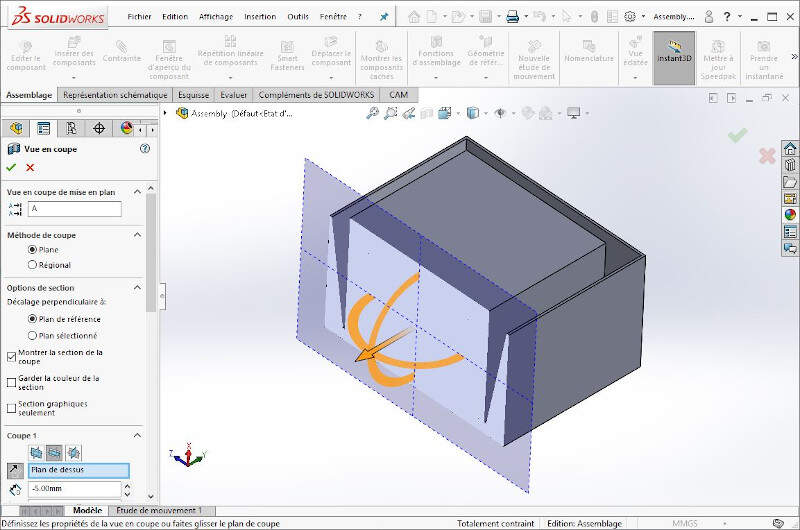
The following picture shows that both part fit to each other.
After I drew in blue and green the part that would be filled with silicone later to validate the conception of the mold boxes.
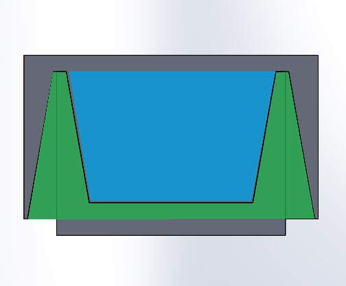
Then I exported both boxes as STL files to use them in Blender and add the head inside it.
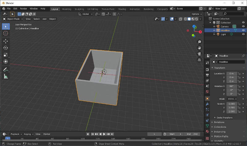
Blender
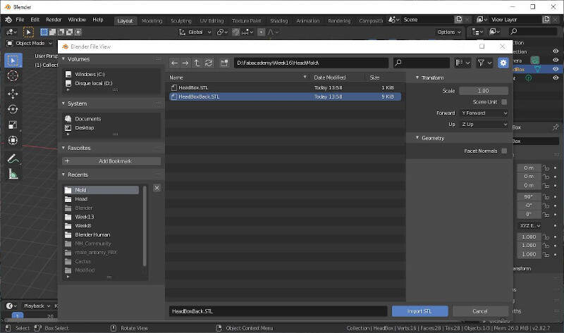
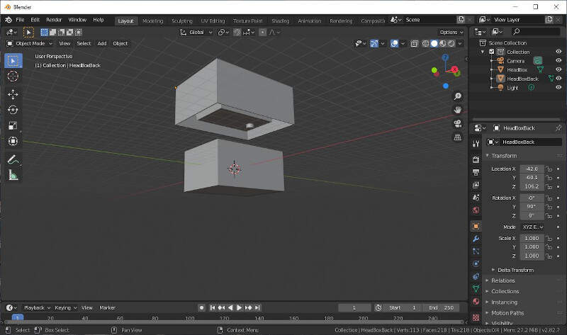
In a new Blender file I imported the head box.
I imported the second box.
I imported the head.
I scaled the head to adapt it to the size of the boxes.
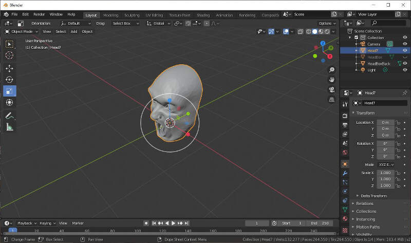
Now it's better.
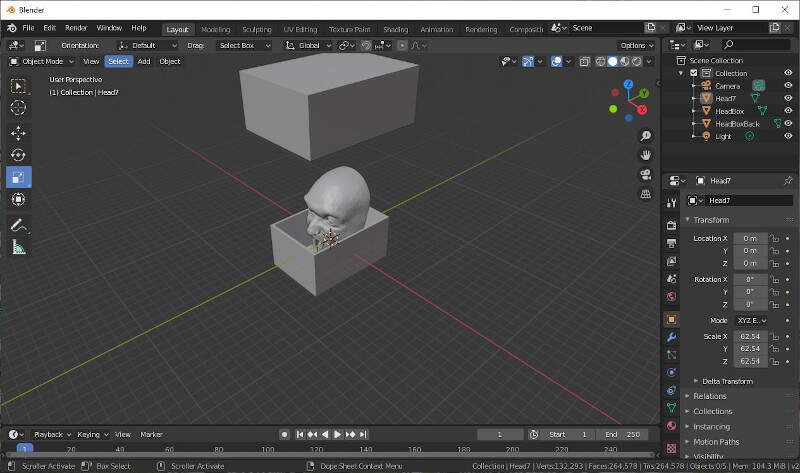
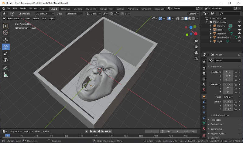
Then I placed the head back right at the bottom of the first box.
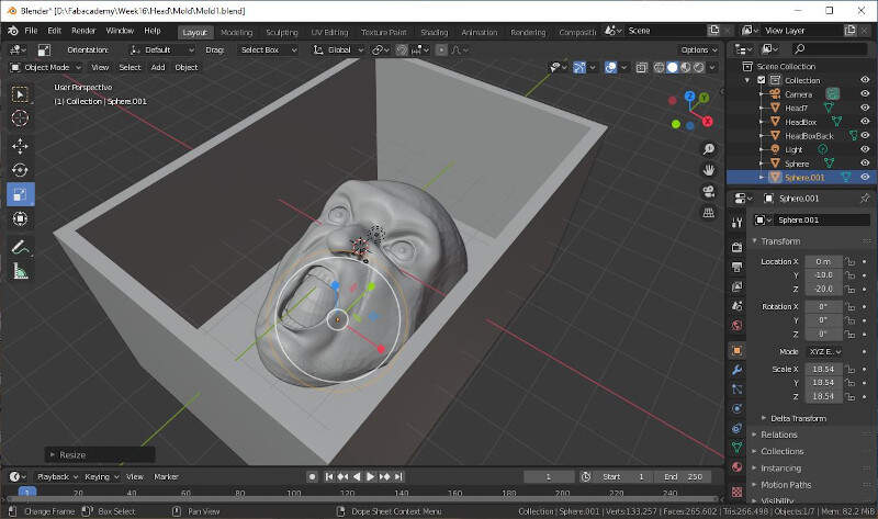
I added a sphere to obstruct the mouth.
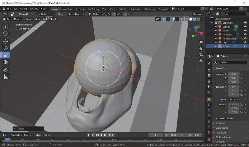
I placed it correctly to keep some details such as the teeth.
I scaled the sphere once more.
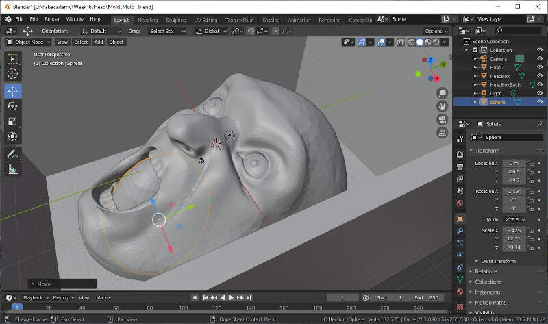
I added a new sphere and merge it with the first one with a boolean modifier.
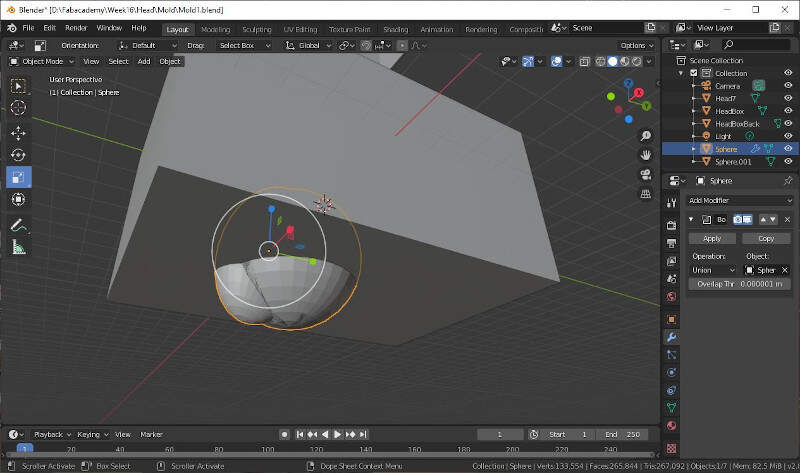
Then I made a mold of the inside of the throat with a second boolean modifier.
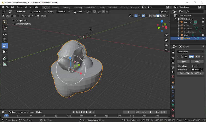
With a cube I cut the throat mold surplus.
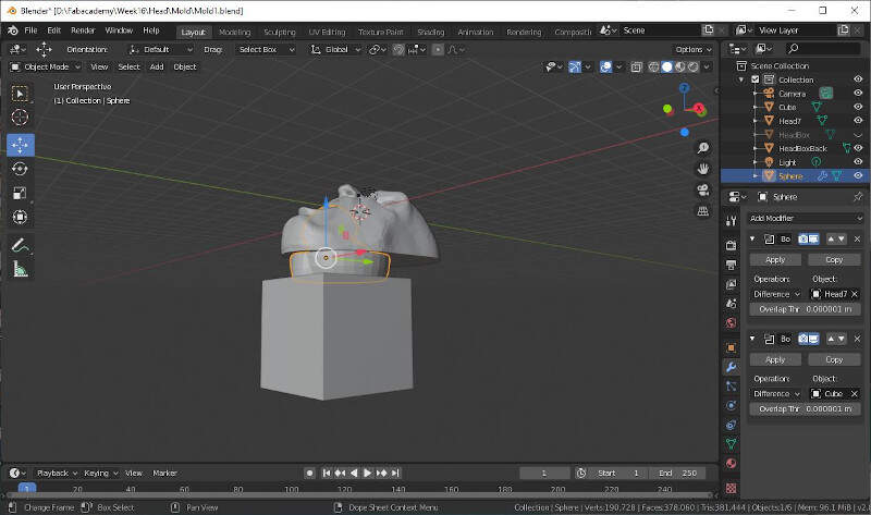
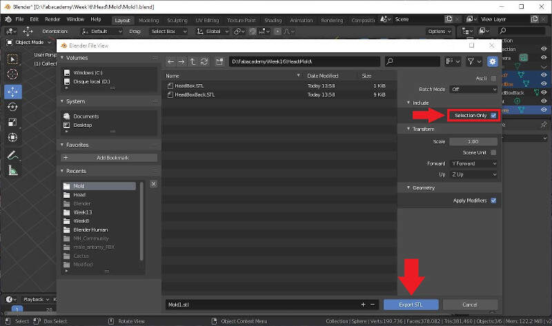
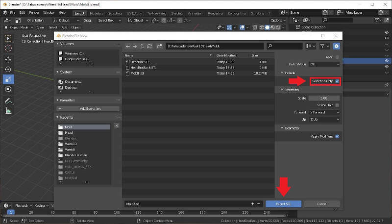
Then I selected the three objects in the right side panel and I exported them as one STL file.
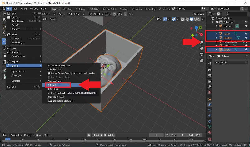
I made sure to tick the check box Selection Only and I saved the file as Mold1.STL.
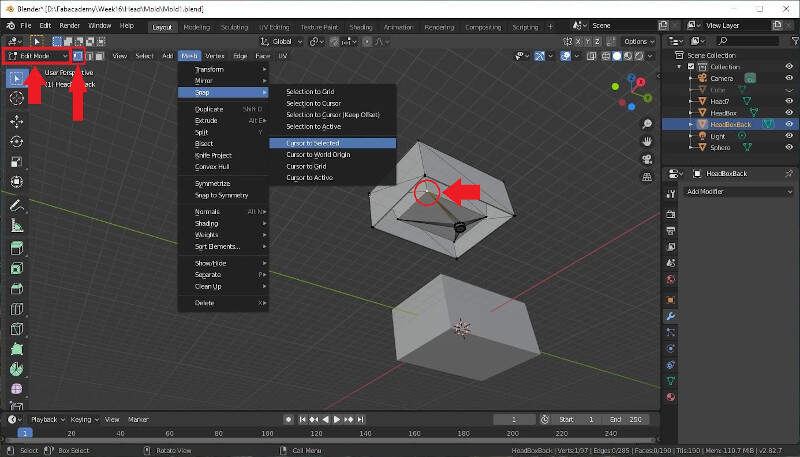
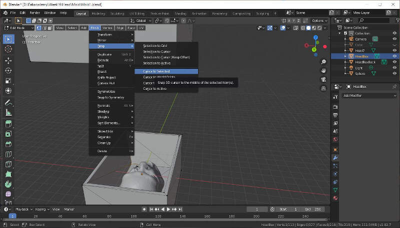
Then I aligned the second box on the top of the other. The procedure in Blender is not straightforward. In first snapped the 3D cursor to the point showed by the arrow in the picture below. Note that this must be done in Edit Mode.
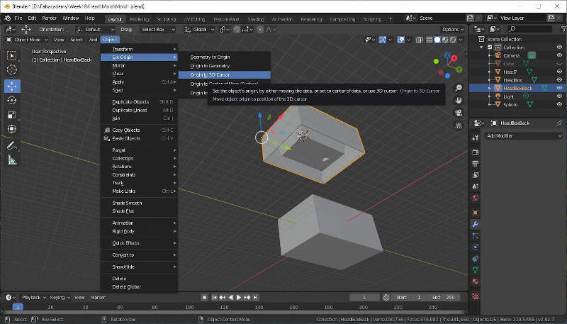
Then I set the Origin of the second box to this point.
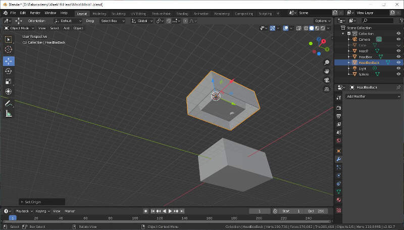
Here is the result.
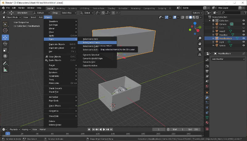
Then I snapped the 3D cursor on the same corner of the first box.
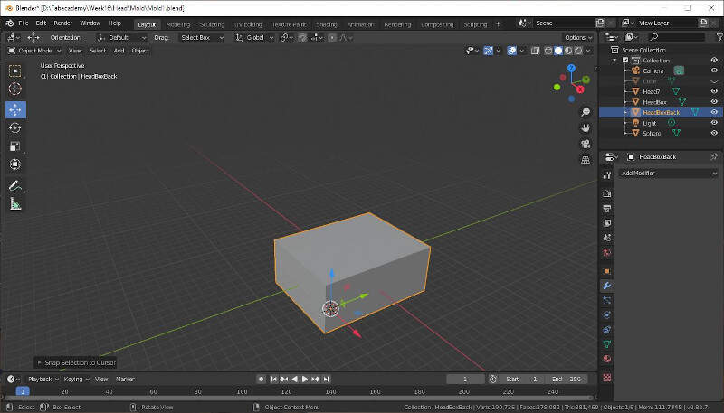
And I moved the second box to this point.
Here is the result.
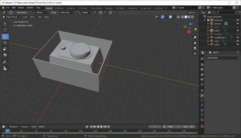
Here is a view when the first box is hidden.
I applied a modifier to remove the throat from the second box.
It was time to export the second mold as a STL file.
Checking of the mesh integrity in Meshmixer
Then I checked the integrity of both molds in Meshmixer.
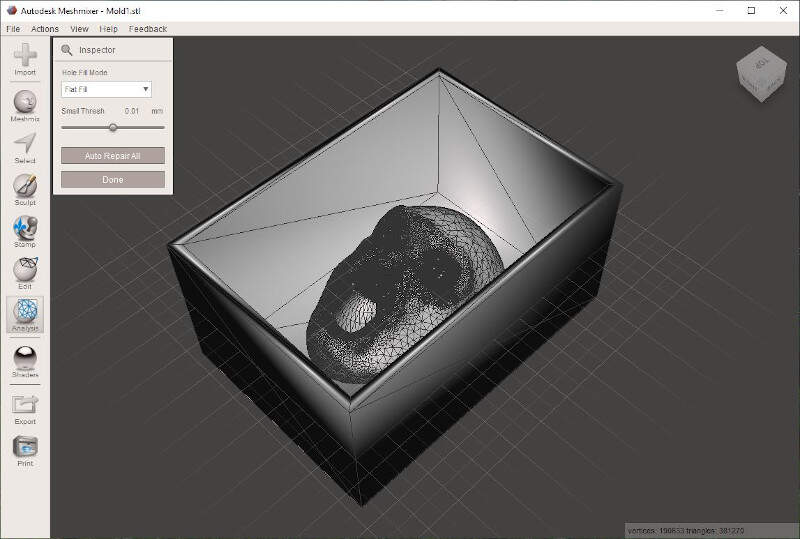
No error was detected.

The files are ready to be milled.
Milling of the high density polyurethane mold
To set the toolpaths I used Fusion then I milled the molds with the high-z s-1000/t CNC Router.
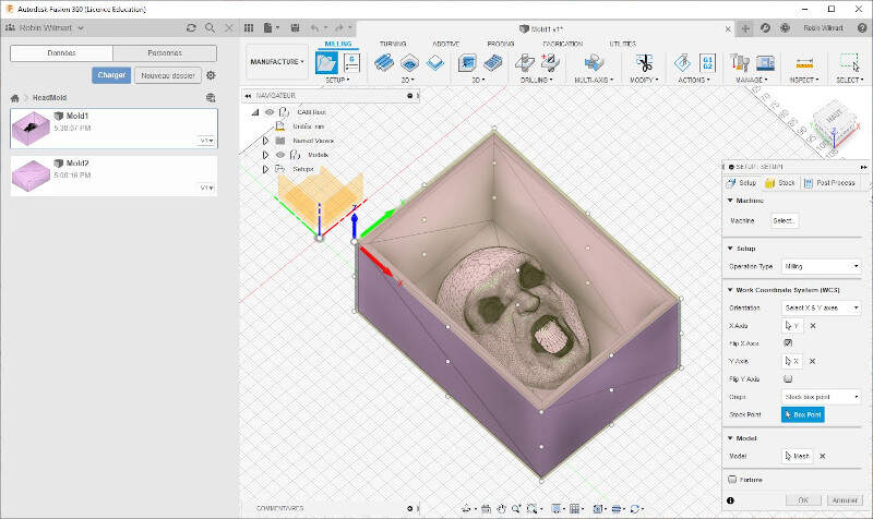
Fusion
In Fusion I first set a new setup in which I defined the stock and set the work coordinates.
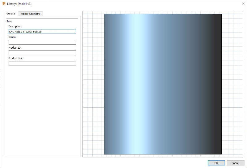
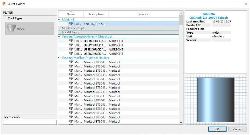
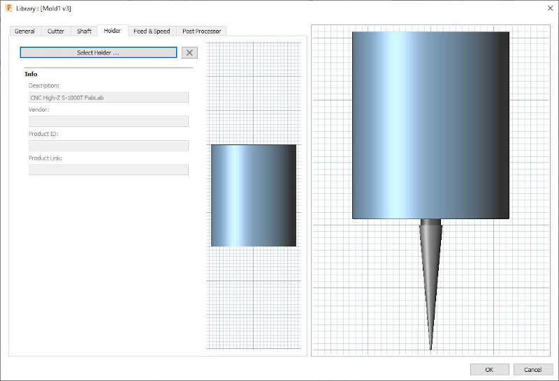
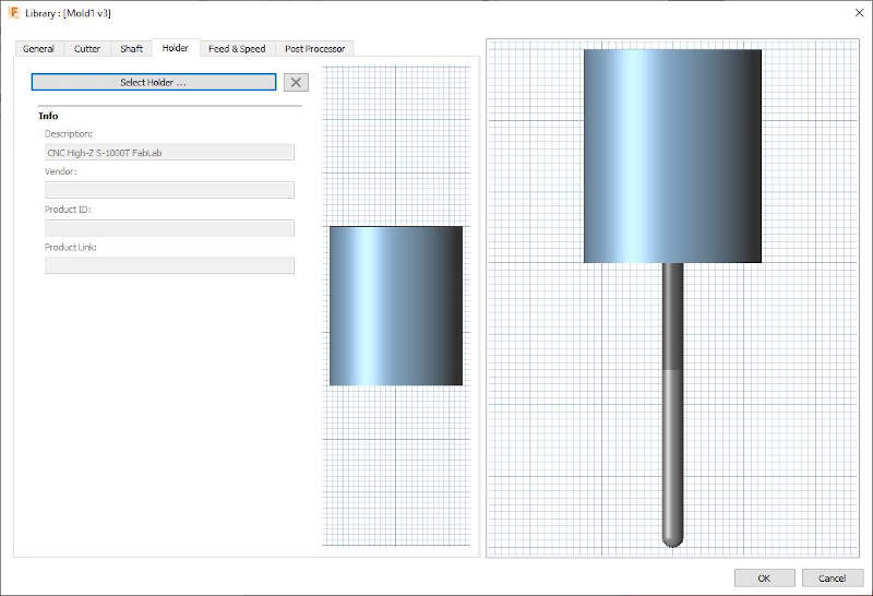
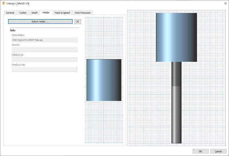
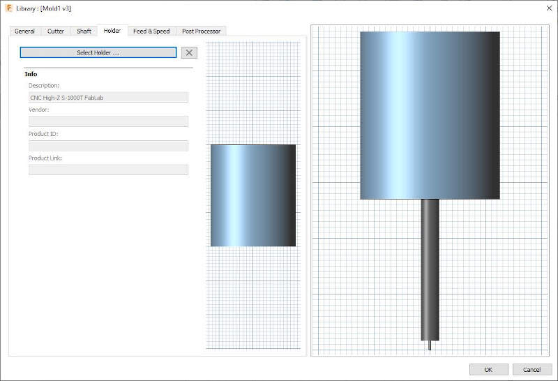
I created a new holder with the size of the FabLab CNC holder.
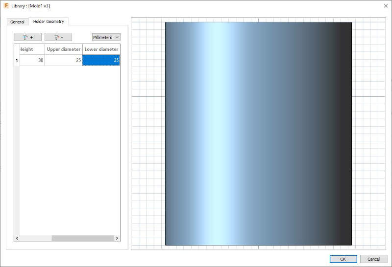
Then I named it to remind it easily.
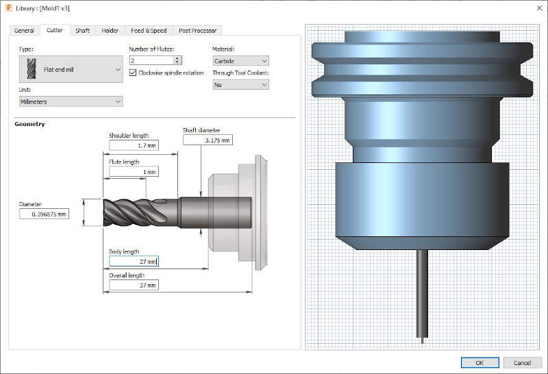
For very small details I planned to used PCB Milling Bits sold by Inventables.
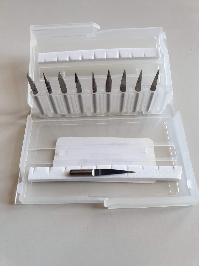
They are made of Carbide and have only one flute. I measured the different parameters such as the shoulder length and the overall length on the actual milling bits and I entered it in Fusion.
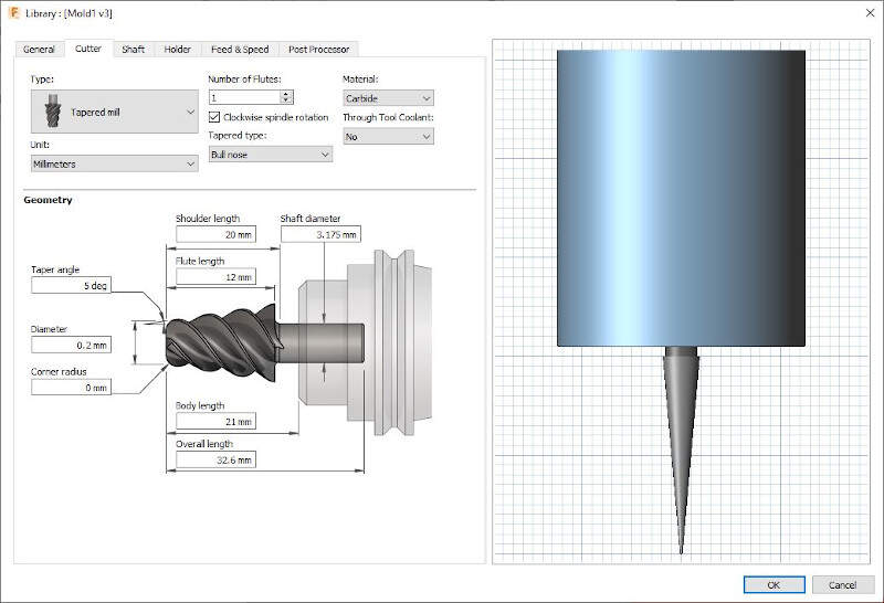
I gave it a name.
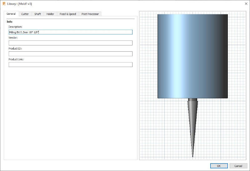
I selected the holder I created later for this tool.
Here is the result.
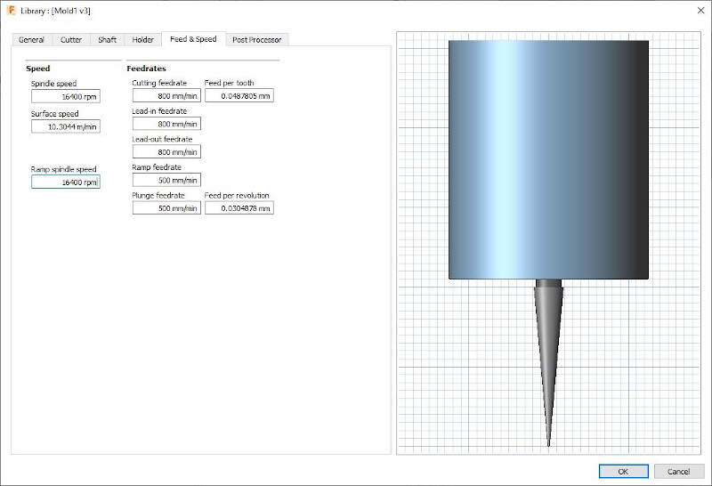
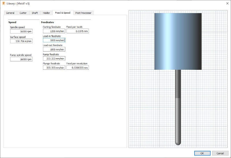
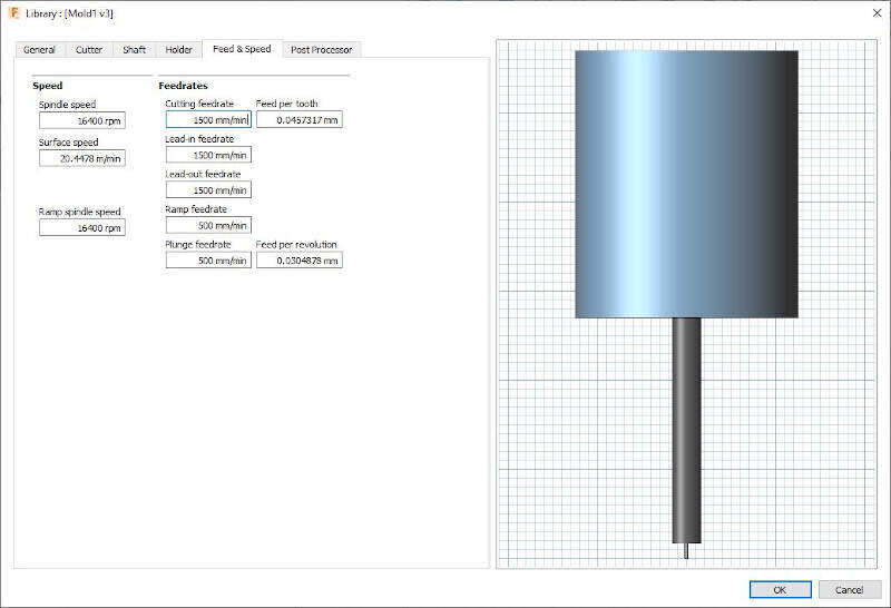
Then I entered the speed and feedrates recommended by BantamTools support for machinable foam.
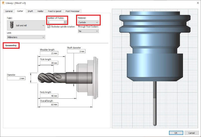
For the first rough cut I decided to use a 6mm flat end mill then a 3 mm ball end mill for a second rough cut.
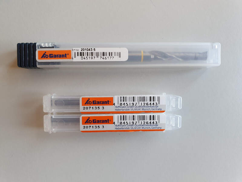
On the website of Garant by looking for the article number on the package "207135 3", I found the datasheet of the 3mm ball end mill.
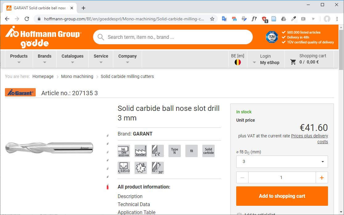
I used the datasheet to set the geometry of the tool in Fusion.
Once again I selected the FabLab CNC holder for this tool.
And I selected the speed and feedrates.
On the same website I found the datasheet of the 6mm flat end mill, article number "201043 6".
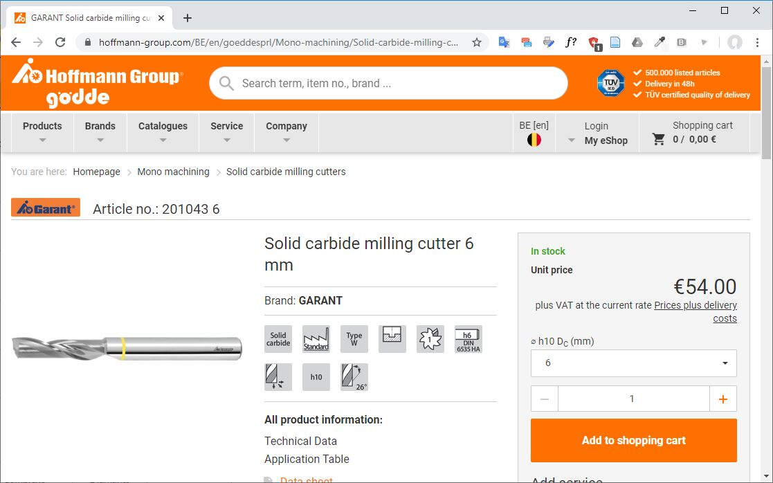
Once again I change the geometry of the tool accordingly to the datasheet.
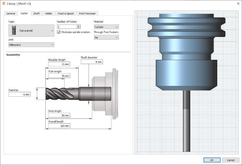
I changed the CNC holder.
I set the speeds and feedrates.

The last tool I planned to used is a 1/64" flat end mill from Bantam Tools. It is an alternative to the PCB milling bits.
I also adapted the CNC holder for this tool.
I changed the speeds and feedrates accordingly to Bantam Tools recommendations for machinable foam.
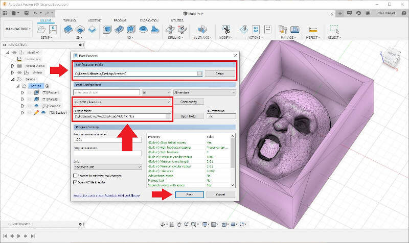
Finally I exported NC files to control the CNC machine by making post processing.
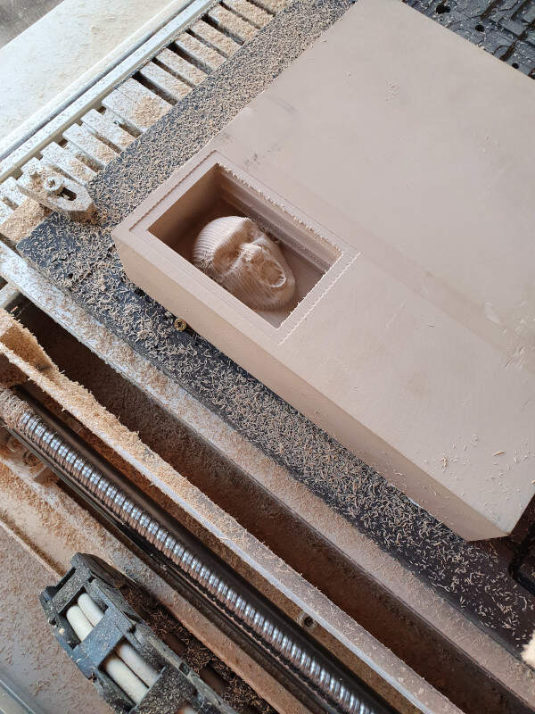
Milling on the high-z s-1000/t CNC Router
To mill my molds I used the HIGH-Z S-1000/T CNC ROUTER. With the milling machine I first made a first cut with a 6mm end flat mill.
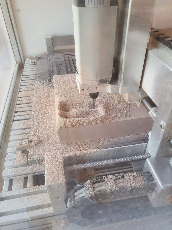
Here is the result after the rough cut.
Then I made a second parallel cut with a 3mm ball end mill.
Here is a video of this cutting.
Milling a second cut with a 3mm ball end mill.
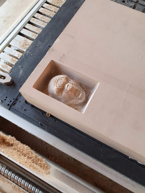
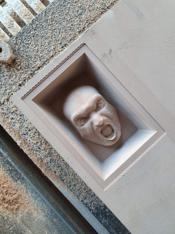
Once the second cut is finished, I made a bit a cleaning to see the result.
Here is the result after cleaning.
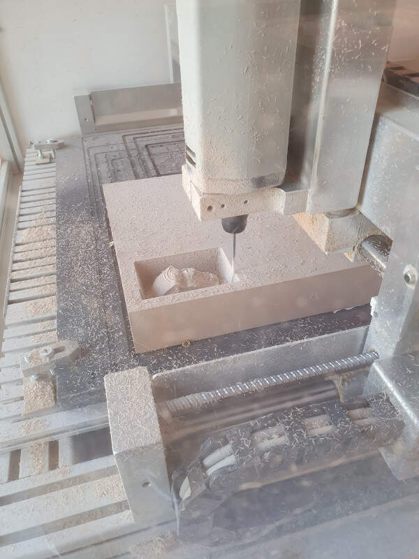
Then I made a new cut with a 1mm flat end mill. As I was satisfied with the surface state of the head I decided it would be the last cut.
Then I cut the edges of the box with a 3mm flat end mill.
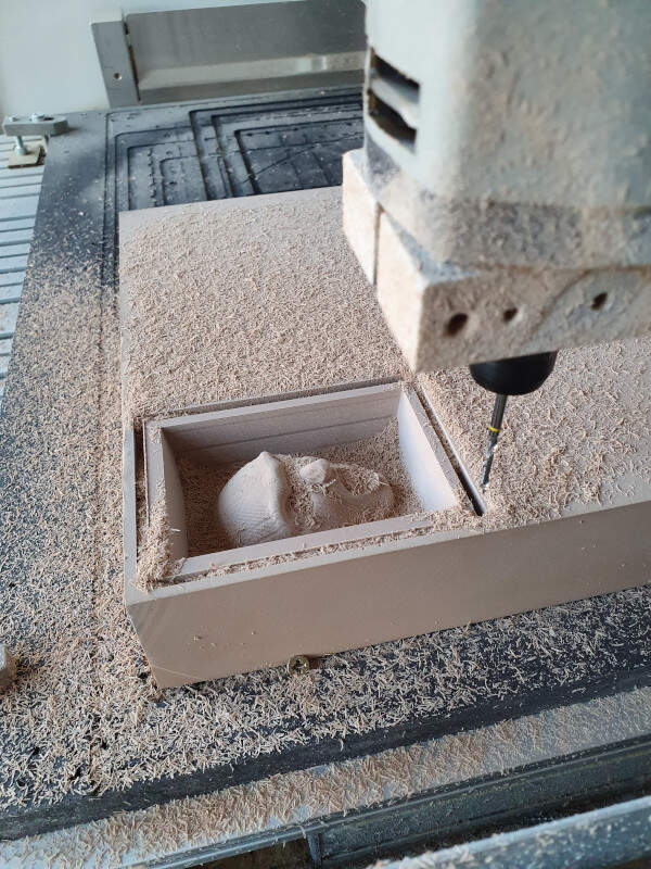
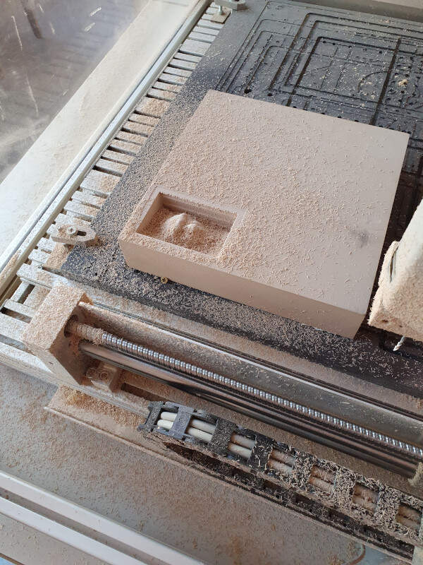
And here is the final result.
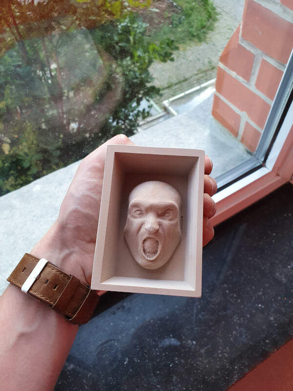
Then I've done the same for the second part of the mold.
Casting the negative molds with silicone
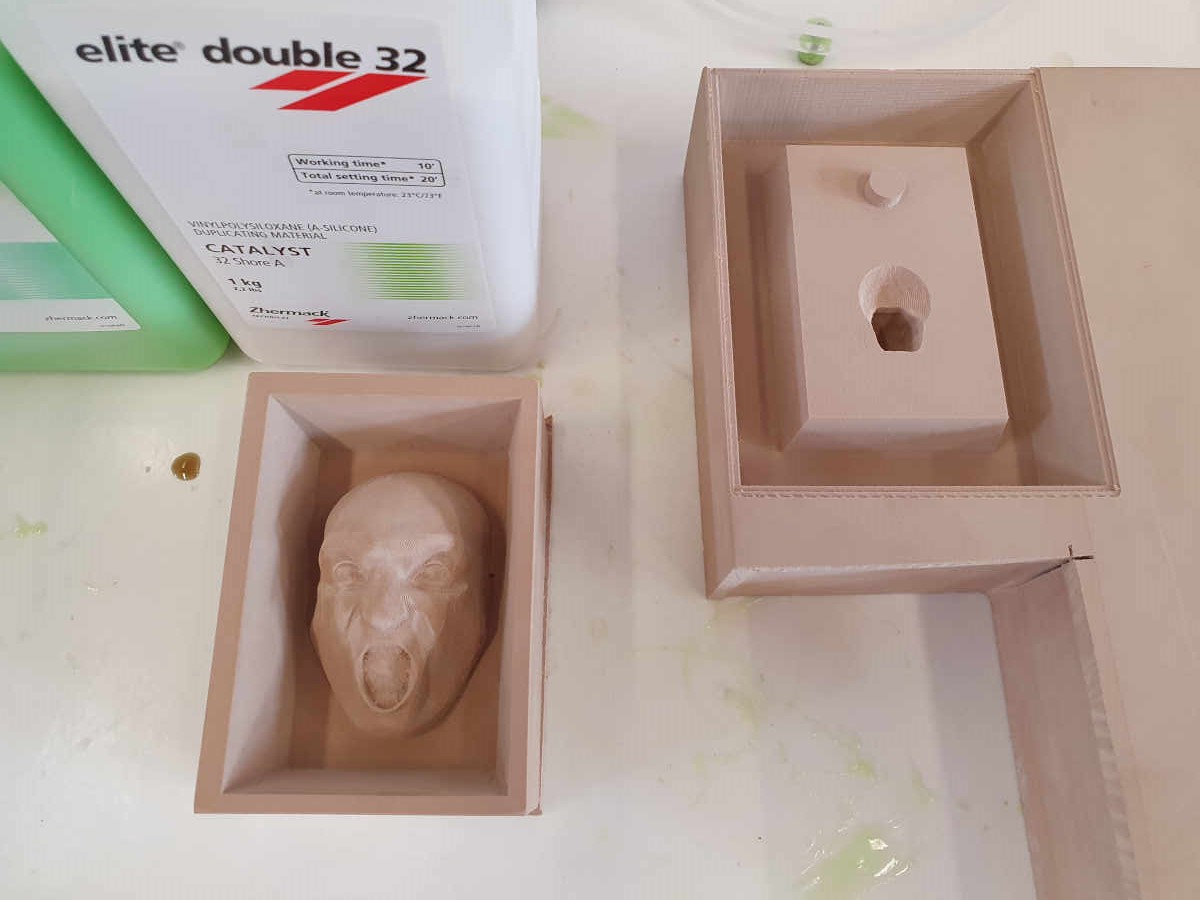
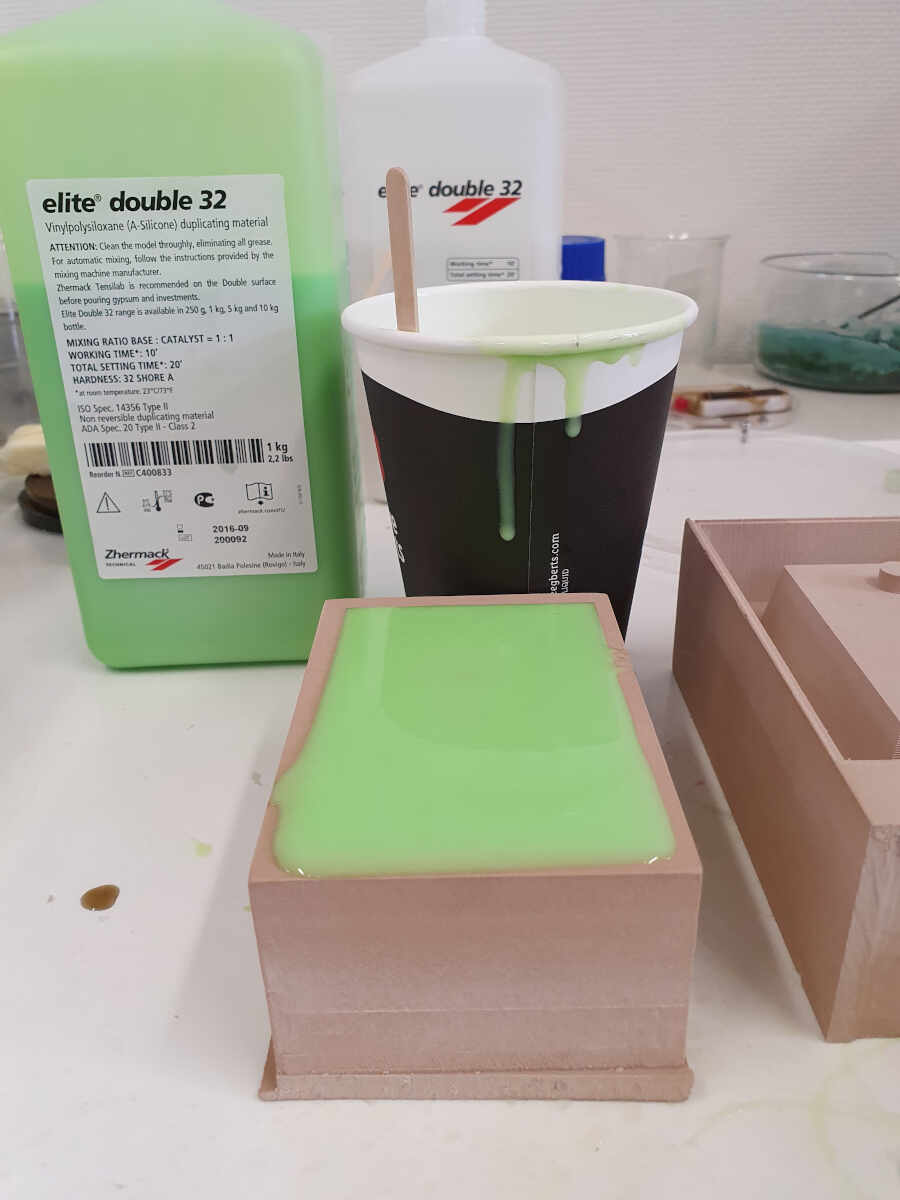
Casting is the act of pouring liquid material into the cavity of a mold. To cast the negative molds with the high density polyurethane foam I used the Elite Double 32 - Zhermack VINYLPOLYSILOXANE, a A-Silicone.

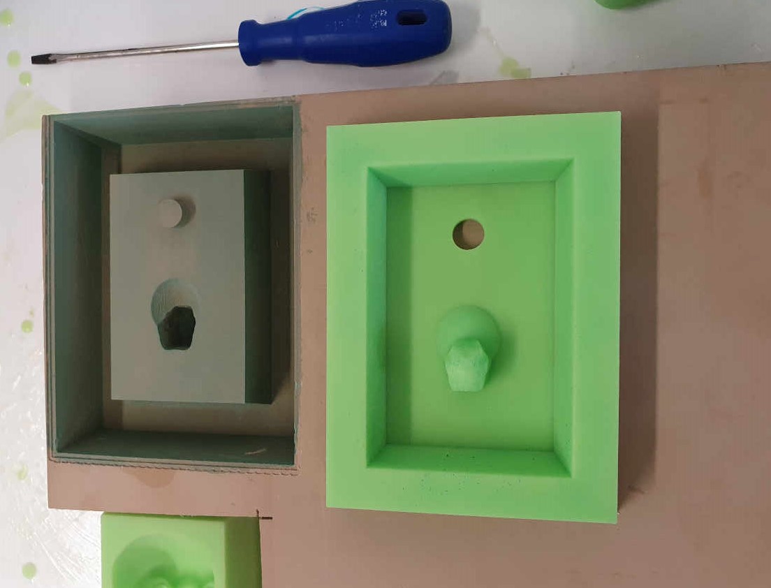
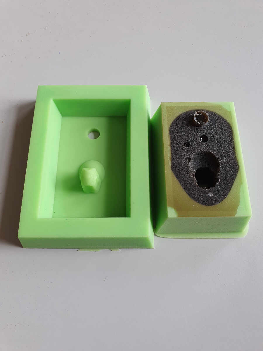
I started with the imprint of the head where I directly put the A-silicone.
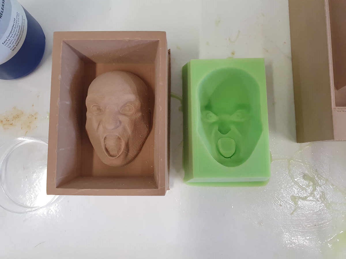
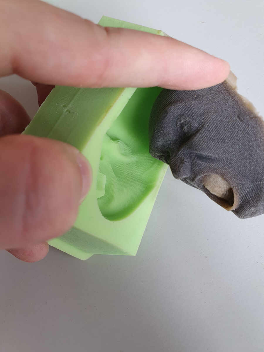
Once the silicone cured I removed it from the imprint with a flat screwdriver.
The task was not easy because the silicone stuck to the polyurethane foam.
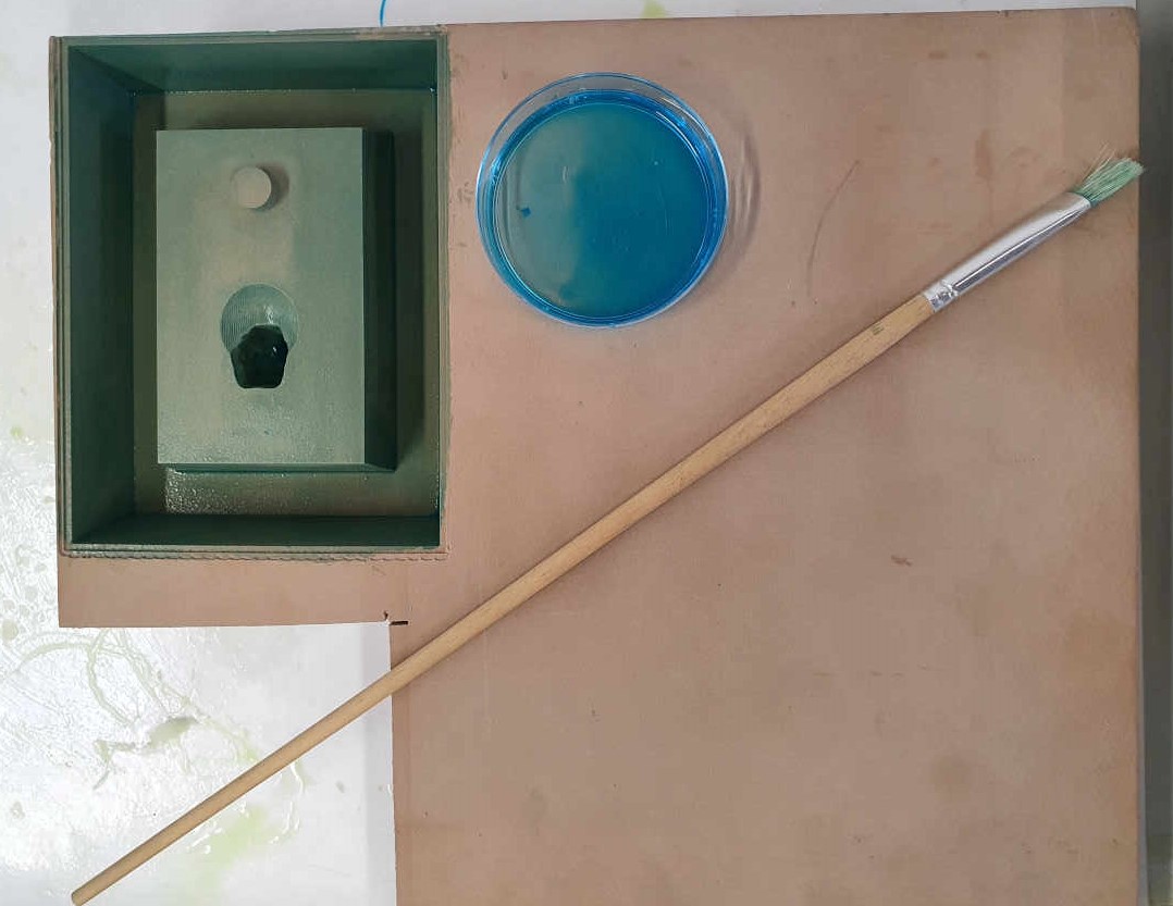
To avoid the same problem with the second part of the mold, I used a release agent (PVA Mould Release Agent 200ml).
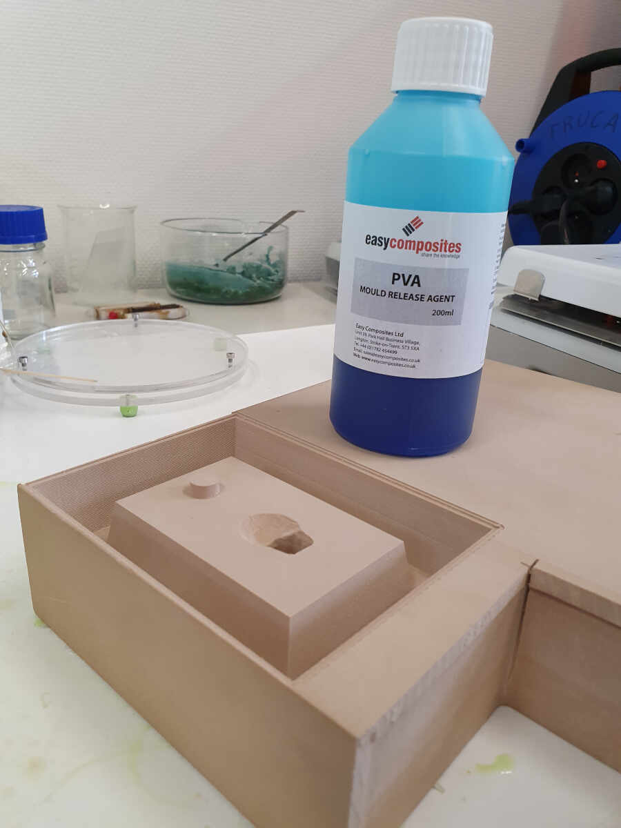
I applied it with a brush before casting the silicone in the mold.
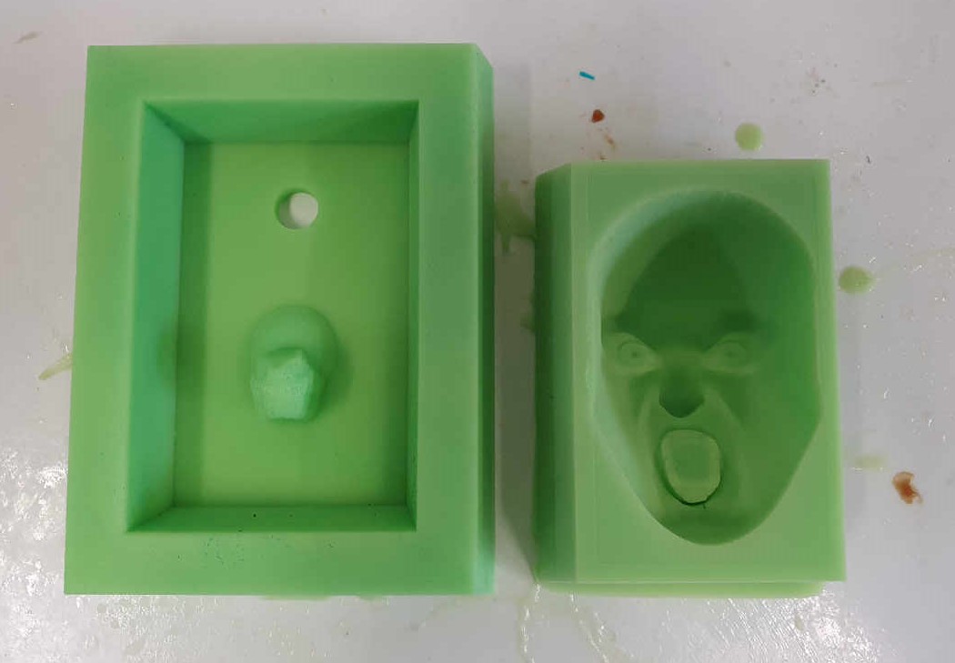
Removing this part of the mold was a piece of cake in comparison with the first one.
Now that I had both parts of the mold it was time to cast the head.
Casting the head with polyurethane
To cast the heads I used a medium flexible polyurethane rubber (Xencast PX60 - Medium Flexible Polyurethane Rubber - 1kg Kit).
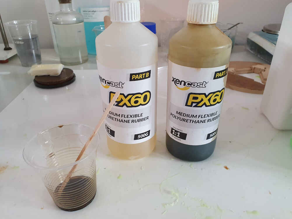
I poured it from a high distance to make the smallest polyurethane trickle as possible to burst the air bubbles, as shown in the video.
Casting the head with polyurethane
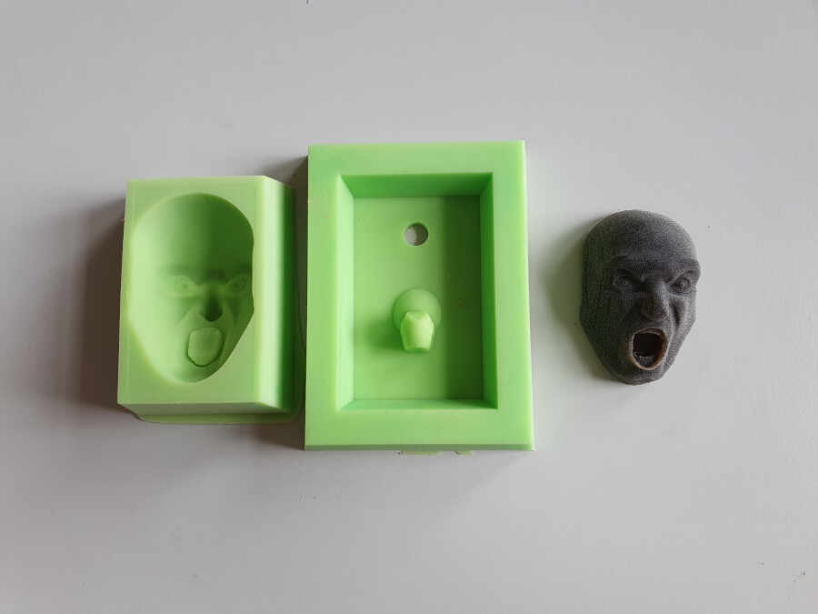
Once the polyurethane cured I removed the first part of the mold.
Then I removed the second part.
I made a little bit of cleaning around the mouth and the head edges. Here is the final result.
If you want to know what this head will be used for, please check my final project page.