Week 15 - Networking and Communications
This week was dedicated to networking and communications.
Networking
IETF
The Internet Engineering Task Force (IETF) is a large open international community of network designers, operators, vendors, and researchers concerned with the evolution of the Internet architecture and the smooth operation of the Internet. The mission of the IETF is to make the Internet work better by producing high quality, relevant technical documents that influence the way people design, use, and manage the Internet.
UDP
UDP stands for User Datagram Protocol. This protocol provides a procedure for application programs to send messages to other programs with a minimum of protocol mechanism. The protocol is transaction oriented, and delivery and duplicate protection are not guaranteed. Applications requiring ordered reliable delivery of streams of data should use the Transmission Control Protocol (TCP).
FAB ACADEMY 2020 source
20200506 networking from Academany on Vimeo.
My Assignment
This week assignment consisted in designing, building, and connecting wired or wireless node(s) with network or bus addresses.
Please follow this link to know about the group assignment.
Serial bus
As a starting point I looked at the examples provided by Neil. Back in the FabLab I'd like to make these boards and stuff them by myself to see to understand how work the code provided. Since I have three arduino boards at home I decided to connect them through the serial bus to make them communicate. To do this I connected each Tx pin together and each Rx pin together. But since on arduino Uno pins 0 and 1 are used for communication with the computer and that connecting anything to these pins can interfere with that communication, (click here for more information about that) I had to make two different codes: one for the first board and one for the two other boards. Because of the interference that can appear on the UNO serial bus, I couldn't use it has a first node. As a consequence I used the Leonardo board that doesn't have that issue. Because of that inference I also had to use the second serial port of the Leonardo to communicate with the UNO boards and its first serial port for USB communication. As a consequence the Tx and Rx of Leonardo are respectively connected to the Rx and Tx of the UNO boards. The following picture presents how the boards are connected.
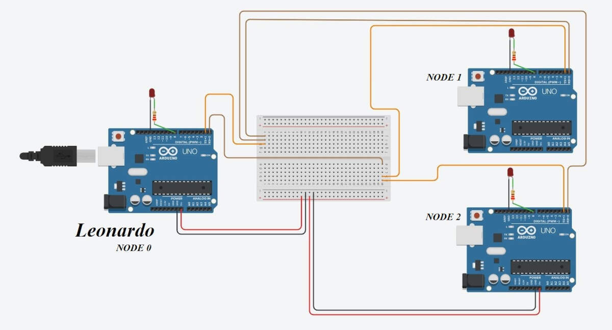
Schematic of the three arduino boards on tinkercad
And here is the mess with the breadboard.
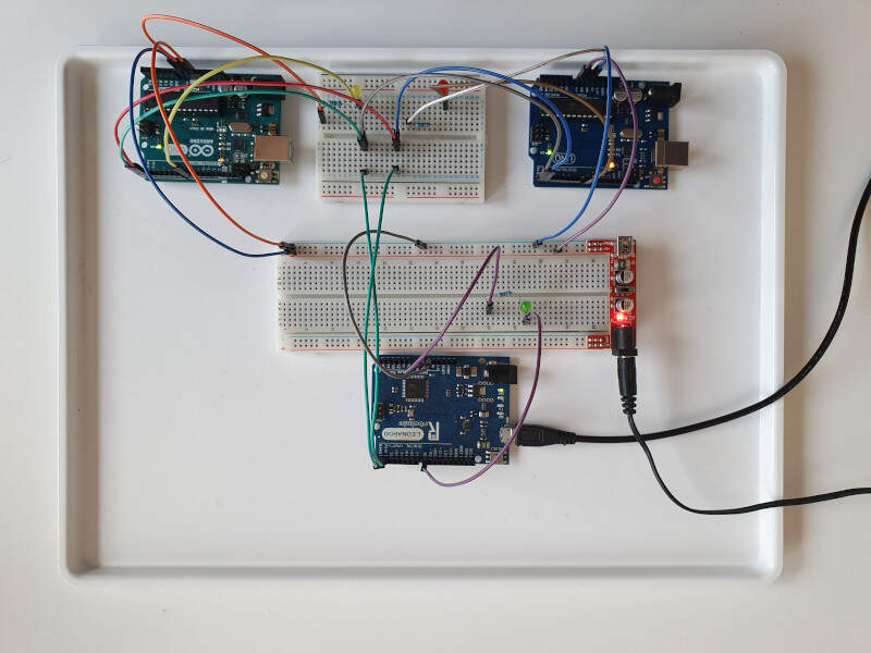
Picture of the three arduino boards
Here is the code I made for the node connected to the computer by the USB port:
#define output(directions,pin) (directions |= pin) // set port direction for output
#define set(port,pin) (port |= pin) // set port pin
#define clear(port,pin) (port &= (~pin)) // clear port pin

#define led_delay() _delay_ms(100) // LED flash delay

#define led_port PORTB
#define led_direction DDRB
#define led_pin (1 << PB4) //Pin IO8


#define node_id '0'

void flash() {
   //
   // LED flash delay
   //
   clear(led_port, led_pin);
   led_delay();
   set(led_port, led_pin);
   }

int message;

void setup() {
  // put your setup code here, to run once:

   Serial.begin(9600);
   Serial1.begin(9600);
   //
   // set clock divider to /1
   //
   CLKPR = (1 << CLKPCE);
   CLKPR = (0 << CLKPS3) | (0 << CLKPS2) | (0 << CLKPS1) | (0 << CLKPS0);
   //
   // initialize output pins
   //
   set(led_port, led_pin);
   output(led_direction, led_pin);
}

void loop() {
  // put your main code here, to run repeatedly:

  flash();


  if (Serial.available() > 0) {

    // read the incoming byte:
    message = Serial.read();
    Serial1.write(message);

    led_delay();
    flash();

    if (message == node_id) {
       led_delay();
       flash();
       Serial.print("node: ");
       Serial.write(message);
       Serial.println();
       led_delay();
       }
    if (Serial1.available() > 0) {
       String chr = Serial1.readString();
       Serial.println(chr);
       }
  }
}
Here is the code I made for the two other nodes connected through serial communication:
#define output(directions,pin) (directions |= pin) // set port direction for output
#define set(port,pin) (port |= pin) // set port pin
#define clear(port,pin) (port &= (~pin)) // clear port pin
#define led_delay() _delay_ms(100) // LED flash delay
#define led_port PORTB
#define led_direction DDRB
#define led_pin (1 << PB0) //Pin IO8
#define node_id '1'
void flash() {
//
// LED flash delay
//
clear(led_port, led_pin);
led_delay();
set(led_port, led_pin);
}
int message;
void setup() {
// put your setup code here, to run once:
Serial.begin(9600);
//
// set clock divider to /1
//
CLKPR = (1 << CLKPCE);
CLKPR = (0 << CLKPS3) | (0 << CLKPS2) | (0 << CLKPS1) | (0 << CLKPS0);
//
// initialize output pins
//
set(led_port, led_pin);
output(led_direction, led_pin);
}
void loop() {
// put your main code here, to run repeatedly:
flash();
if (Serial.available() > 0) {
// read the incoming byte:
message = Serial.read();
flash();
led_delay();
if (message == node_id) {
led_delay();
flash();
Serial.print("node: ");
Serial.write(message);
Serial.println();
led_delay();
}
}
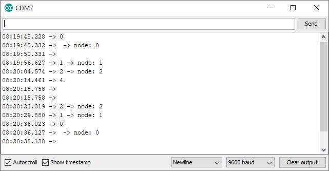
}When a message is sent on the serial port, the LED blinks twice. If the message is the address of one node, this specific node LED blinks three times. The following video presents the results:
Communication between three arduino boards through serial bus
As you can see the microcontrollers behave like expected but unfortunately the message from the two farthest nodes never come back/ It is not displayed on the USB serial and I don't have a clue why. Note that the very same code was not working earlier because I didn't had a common ground for both microcontrollers, so make sure that all boards have the same ground.
This behavior is due to a collision between the nodes 1 and 2 because they both try to impose their state on the Tx line. To solve that issue I needed to set the Tx line of both nodes 1 and 2 as an input while they are not requested to talk. To be able to do that, I changed a little bit the schematic.
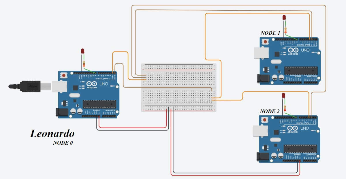
Picture of the three arduino boards
Then I modified the code of NODE 0. With the command (PORTB &= (~(1 << PB4))); I made such as the LED was turned off while receiving data on the serial port.
#define output(directions,pin) (directions |= pin) // set port direction for output
#define set(port,pin) (port |= pin) // set port pin
#define clear(port,pin) (port &= (~pin)) // clear port pin

#define led_delay() _delay_ms(100) // LED flash delay
#define led_delay_receive() _delay_ms(800) // LED flash delay

#define led_port PORTB
#define led_direction DDRB
#define led_pin (1 << PB4) //Pin IO8


#define node_id '0'

void flash() {
   //
   // LED flash delay
   //
   clear(led_port, led_pin);
   led_delay();
   set(led_port, led_pin);
   }

int message;

void setup() {
  // put your setup code here, to run once:

   Serial.begin(9600);
   Serial1.begin(9600);
   //
   // set clock divider to /1
   //
   CLKPR = (1 << CLKPCE);
   CLKPR = (0 << CLKPS3) | (0 << CLKPS2) | (0 << CLKPS1) | (0 << CLKPS0);
   //
   // initialize output pins
   //
   set(led_port, led_pin);
   output(led_direction, led_pin);
}

void loop() {
  // put your main code here, to run repeatedly:

  flash();


  if (Serial.available() > 0) {

    // read the incoming byte:
    message = Serial.read();
    Serial1.write(message);

    led_delay();

    (PORTB &= (~(1 << PB4))); //Turn off the LED

    if (Serial1.available() > 0) {
       String chr = Serial1.readString();
       Serial.println(chr);
       }

    flash();

    if (message == node_id) {
       Serial.print(" -> node: ");
       Serial.write(message);
       led_delay_receive();
       }

    (PORTB &= (~(1 << PB4))); //Turn off the LED

  }
}
Then I modified the code of both NODE 1 and NODE 2 in such as way that the Tx line would be set up as an input (i.e. anything connected to this line is connected to a high impedance) while the nodes are not requested to talk. This was done by emulating a serial communication on pins 2 and 3 with the <SoftwareSerial.h> library and the commands #include <SoftwareSerial.h>, #define serial_pin_in 2, #define serial_pin_out 3 and SoftwareSerial mySerial(serial_pin_in,serial_pin_out);.
In the setup() function, I initialized the serial pins both as inputs with the following commands: pinMode(serial_pin_out,INPUT); and pinMode(serial_pin_in,INPUT);. Then, in the loop() function, under the condition that the message received on Rx is equal to the node id (if (message == node_id)), I set Tx as an output (pinMode(serial_pin_out,OUTPUT);), sent the message (mySerial.write(message);) and close the transmission by setting Tx back to an input (pinMode(serial_pin_out,INPUT);).
#include <SoftwareSerial.h>

#define output(directions,pin) (directions |= pin) // set port direction for output
#define set(port,pin) (port |= pin) // set port pin
#define clear(port,pin) (port &= (~pin)) // clear port pin

#define led_delay() _delay_ms(100) // LED flash delay
#define led_delay_receive() _delay_ms(800) // LED flash delay

#define led_port PORTB
#define led_direction DDRB
#define led_pin (1 << PB0)


#define node_id '1'

#define serial_pin_in 2
#define serial_pin_out 3

SoftwareSerial mySerial(serial_pin_in,serial_pin_out);

void flash() {
   //
   // LED flash delay
   //
   clear(led_port, led_pin);
   led_delay();
   set(led_port, led_pin);
   }

int message;

void setup() {
   //
   // set clock divider to /1
   //
   CLKPR = (1 << CLKPCE);
   CLKPR = (0 << CLKPS3) | (0 << CLKPS2) | (0 << CLKPS1) | (0 << CLKPS0);
   //
   // initialize output pins
   //
   set(led_port, led_pin);
   output(led_direction, led_pin);

   // initialize serial pins
   //
   pinMode(serial_pin_out,INPUT); //close Rx port by setting it as an input.
   pinMode(serial_pin_in,INPUT);  //set Tx as an input.
   //
   // initialize serial
   //
   mySerial.begin(9600);
}

void loop() {
  flash();

  if (mySerial.available() > 0) {

    // read the incoming byte:
    message = mySerial.read();

    led_delay();

    if (message == node_id) {
       pinMode(serial_pin_out,OUTPUT);
       mySerial.write(" -> node: ");
       mySerial.write(message);
       led_delay_receive();
       pinMode(serial_pin_out,INPUT);
       }

    (PORTB &= (~(1 << PB0))); //Turn off the LED
  }
}
As a matter fact, collisions are now avoided. The following picture shows that the nodes are now able to communicate between each other.
The serial monitor finally shows the answer of all three nodes
I²C Communication Protocol
In this section I tested the I²C communication protocol that requires two communication lines: SDA to exchange data and SCL to share a clock signal. Since all the microprocessors share a clock, this communication protocol is said to be synchronous. The location of the SDA and SCL pins is available on the datasheet of the microcontrollers that have ones. On the Arduino boards SDA and SCL are respectively on pins A4 and A5 for the UNO and 3 and 2 for the LEONARDO. Both SDA and SCL require a pull-up resistance. The following picture illustrates the wiring of the three Arduino boards used to test the I²C protocol.
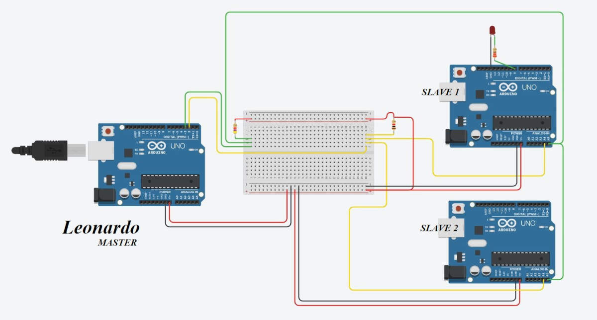
Wiring of the three boards for I²C communication
To help me understand the I²C protocol in general and in particular from a programming point of view I read articles about the <Wire.h> arduino library: I2C, Bibliothèque Wire : I2C, Wire Library, Master Reader/Slave Sender and Master Writer/Slave Receiver. These sources included several examples among which I found a I²C scanner that might be very useful when one doesn't know a slave address. Here is the code of the scanner that I modified to suit to my application. I loaded it on the LEONARDO board, also called the MASTER.
#include <Wire.h>
// NE PAS OUBLIER LES 2 RESISTANCES DE 4,7KOHMS ENTRE SDA ET +5V ET ENTRE SLC ET +5V

void setup()
{
  Wire.begin();
  Serial.begin(9600);
  Serial.println("\nI2C Scanner");
}


void loop()
{
  byte error, address;
  int nDevices;

  Serial.print("Scanning");

  nDevices = 0;
  for(address = 1; address < 127; address++ )
  {
    // La valeur de retour de Wire.endTransmission()
    // est false (0) si le peripherique existe a cette adresse
    Wire.beginTransmission(address);
    error = Wire.endTransmission();
    Serial.print(".");

    if (error == 0)
    {
      Serial.println("");
      Serial.print("I2C device found at address 0x");
      if (address<16)
        Serial.print("0");
      Serial.print(address,HEX);
      Serial.println("  !");
      nDevices++;
      //break; // commenter cette ligne si plusieurs peripheriques I2C coexistent sur le bus
             // sinon le test s'arrete des le premier trouve
    }
    else if (error==4)
    {
      Serial.println("");
      Serial.print("Unknow error at address 0x");
      if (address<16)
        Serial.print("0");
      Serial.println(address,HEX);
    }
    delay(50);
  }
  if (nDevices == 0)
  {
    Serial.println("");
    Serial.println("No I2C devices found\n");
  }
  else
    Serial.println("done\n");

  delay(3000);           // on attend 3 secondes et on recommence
}
The other two boards (the UNO ones) were configured as slaves. To the first slave I gave the address 121. In the setup(), I defined two interrupts: Wire.onReceive(receiveEvent); and Wire.onRequest(requestEvent);. The first one (Wire.onReceive(receiveEvent);) will be called each time the slave receives something from the master. In this particular case, the slave will receive a byte from the master and save it in a register. Afterwards it will increment an event count. The second function void requestEvent() will be called each time the master requires a value from the slave. In this particular case, the slave will send a value that is computed independently by the slave. This value is between 0 and 64.
#include <Wire.h>
// NE PAS OUBLIER LES 2 RESISTANCES DE 4,7KOHMS ENTRE SDA ET +5V ET ENTRE SLC ET +5V

int Windex = 0;
byte I2Cdata[1];
int EventCount=0;
byte val = 0;

void setup() {

  // Initialisation de l' I2C
  Wire.begin(121);
   // rejoindre le bus avec l'adresse #121
  Wire.onReceive(receiveEvent);
   // enregistrement du handler "receive"
  Wire.onRequest(requestEvent);
   // enregistrement du handler "request"

}

void loop() {

  val++;
  if(val == 64) // if reached 64th position (max)
  {
    val = 0;    // start over from lowest value
  }
  delay(500);

}

//------------------------------------------------------
// réception d'un événement I2C
// mode Esclave
// cette fonction "handler" a été enregistrée dans le setup()
//------------------------------------------------------

void receiveEvent(int howMany)
{
  byte c;

  while(Wire.available()) {

  c = Wire.read();
   // reçoit un octet
  I2Cdata[Windex++] = c;
   // stockage dans un tampon circulaire
  if (Windex == 64) Windex = 0;
  }
  EventCount++;
}

//------------------------------------------------------
// réponse à une requête I2C
// mode Esclave
// cette fonction "handler" a été enregistrée dans le setup()
//------------------------------------------------------

void requestEvent()
{
  Wire.write(val);
   // répond par un message d'un octet
}
The second slave address is 7. This slave also has two types of interrupts. On the receiveEvent() function, it will read a byte from the master and, depending on the value of this byte, the slave will turn on or off a LED on pin 8. Afterwards the slave will increment an event count value. On the requestEvent() function, the slave will send a char and an int. The char is a letter that also evolves independently in the slave between 'a' and 'z' in the alphabetic order. The int is the value corresponding to the event count.
#include <Wire.h>
// NE PAS OUBLIER LES 2 RESISTANCES DE 4,7KOHMS ENTRE SDA ET +5V ET ENTRE SLC ET +5V

int Windex = 0;
byte I2Cdata[1];
int EventCount=0;
char val = 'a';
int LED = 8;

void setup() {

  // Initialisation de l' I2C
  Wire.begin(7);
   // rejoindre le bus avec l'adresse #7
  Wire.onReceive(receiveEvent);
   // enregistrement du handler "receive"
  Wire.onRequest(requestEvent);
   // enregistrement du handler "request"

  pinMode(LED, OUTPUT);

}

void loop() {

  val++;
  if(val == 'z') // if reached 64th position (max)
  {
    val = 'a';    // start over from lowest value
  }
  delay(500);

}

//------------------------------------------------------
// réception d'un événement I2C
// mode Esclave
// cette fonction "handler" a été enregistrée dans le setup()
//------------------------------------------------------

void receiveEvent(int howMany)
{
  byte c;

  while(Wire.available()) {

  c = Wire.read();
   // reçoit un octet
  I2Cdata[Windex++] = c;
   // stockage dans un tampon circulaire
  if (Windex == 64) Windex = 0;
  }
  EventCount++;

  if(c > 127) digitalWrite(LED, LOW);
  else digitalWrite(LED, HIGH);

}

//------------------------------------------------------
// réponse à une requête I2C
// mode Esclave
// cette fonction "handler" a été enregistrée dans le setup()
//------------------------------------------------------

void requestEvent()
{
  Wire.write(val);
  Wire.write(EventCount);
}
The following picture shows a display of the serial monitor when the master (connected to the computer via USB) is scanning the devices on the I²C bus. As a result, it provides the addresses of both slaves in hexadecimal: 0x79 = 121 and 0x07 = 7.
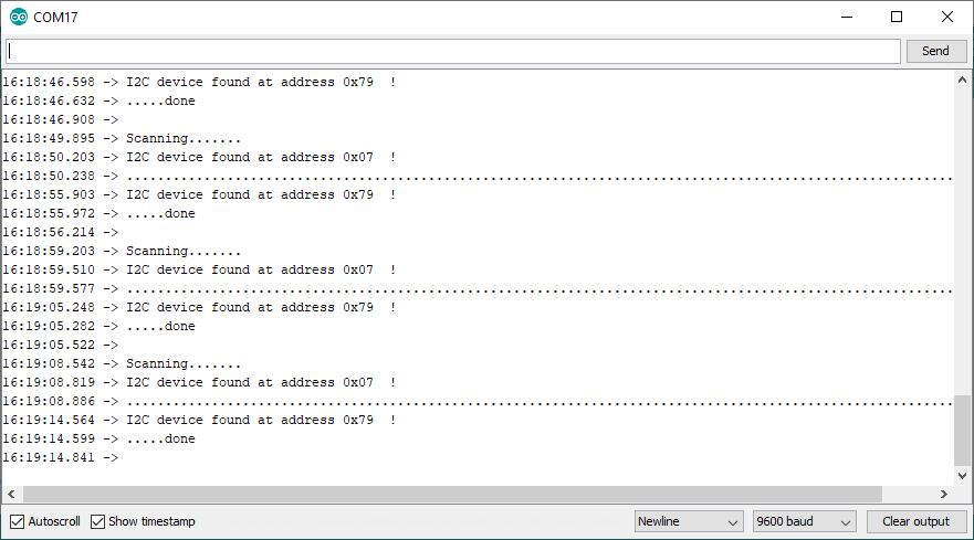
Result of the scan on the serial monitor
Then, to communicate with the slaves, I loaded a different code on the master. In the loop(), it will first send a request to the first slave and ask for an answer of one byte only. Then, as long as the connection is available (i.e. as long as the master has not received 1 byte from the slave), the master will read the answer and print it on the serial monitor. Afterwards, the master will make a transmission to the second slave (Wire.beginTransmission(7);) and send it a value between -10 and 10. The transmission ends with the command Wire.endTransmission();. Finally the master will send a request to the second slave and except an answer of two bytes. The answer will be printed on the serial monitor.
#include <Wire.h>

int val = 0;

void setup()
{
  Wire.begin();
   // initialisation de la liaison I2C
  Serial.begin(9600);
   // initialisation de la liaison série vers la console
}

void loop()
{
  Wire.requestFrom(121, 1);
   // demande à recevoir 1 octet du périphérique d'adresse #121 (0x79)

  while(Wire.available())
   // attente des octets
  {
    byte c = Wire.read();
    // réception des octets, un par un
    Serial.print("Device 121: ");
    Serial.println(c);
    // envoi à la console
  }

  Wire.beginTransmission(7);
   // début de la transmission au périphérique d'adresse #7 (0x07)
  Wire.write(val);
   // envoi d'un octet val
  Wire.endTransmission();
   // envoi de la somme de contrôle et fin de transmission

  Wire.requestFrom(7, 2);
   // demande à recevoir 2 octet du périphérique d'adresse #7 (0x07)

  int i = 0;

  while(Wire.available())
   // attente des octets
  {
    byte c = Wire.read();
    // réception des octets, un par un
    if (i == 0){
      Serial.print("Device 7 - Alphabet: ");
      Serial.println(char(c));
      // envoi à la console
      i++;
    }
    else{
      Serial.print("Device 7 - EventCount: ");
      Serial.println(c);
      // envoi à la console
      i=0;
    }
  }

  val++;
  if(val == 10)
  {
    val = -10;
  }

  Serial.print("Value: ");
  Serial.println(val);

  delay(200);
}
The following picture shows the serial monitor where we got one value from the first slave (device 121) and two values from the second slave (device 7). The serial monitor also shows the value that is sent to the second slave. If this value is negative, the LED turns off. On the contrary, the LED turns on.
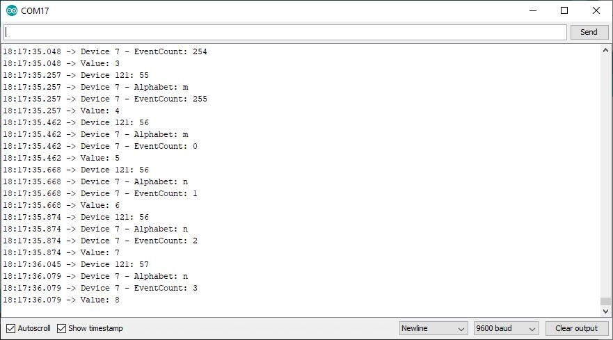
I²C exchange of data printed on the serial monitor
The following video shows the LED blinking because the value that the second slave receives, periodically changes of sign.
Communication between three arduino boards through I²C
Open a port on my modem
To know if I had either a public or a private IP address I followed this procedure. In a web-browser I typed the following IP address http://192.168.0.1/. As explained here the username was "voo" and the password was beneath the VOO modem next to "Password (WPA)".
By following this procedure I found my modem IP address. As this procedure depends on each Internet provider I didn't find useful to explain it here. As my IP address is not starting by 10.xx my IP address is not private. That's a good news!
Then I followed this procedure to manually open a port on my modem by adding a NAT rule. I entered the IPv4 address of my computer that I found with the command ipconfig in the command prompt and I chose a UDP port.
After that I was finally able to communicate with the outside world.
What I want to do
Serial bus
- Use a simple asynchronous serial bus (RS-232,RS-422,RS-485) to communicate (through wires between my microcontrollers).
- Use I2C to detect device plugging.
- Use SPI to read a SD card .
- Use LUFA to make the device look as a midi device or an audio device while connected to a computer through USB.
Physical media
- Read about Neil lecture about physical media.
- Read about wired modules and wireless (Bluetooth, Wi-Fi, LiFi,...).
Modulation/Channel sharing/ errors
- Read more about these three sections.
Networking
- Read the book Computer Networks.
- Test TCP