Electronics Design
I’ve chosen to use Eagle for this assignment due to tutorial availability on the fab academy tutorial site and for it’s functionality. Eagle is a great software for designing PCB’s it has functions like auto routing that helps allot when laying the microchips on your board.
Installation:
- Install Eagle
- Install Fab libraries (Eagle Library folders are located in Documets- Linux user)
To read:
Attiny44
Parts:
- LED (1)
- 6 Pin Programming Header (1)
- Microcontroller Attiny44(1)
- FTDI Header(1)
- 20Mhz Resonator(1)
- 10K Resistor(2)
- Resistor 499 ohms(1)
- Capacitor 1uf(1)
- Tactile 6mm Switch(1)
Fab Academy Tutorial
-
First thing we want to do is to choose the parts needed for this board by clicking on add parts icon located on the left toolbar

-
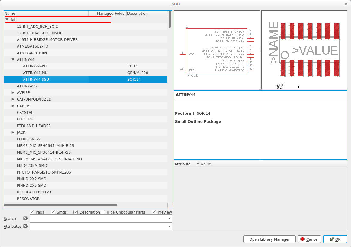
Clicking on add parts will open the Eagle library – choose fab archives and add parts to the schematic window.
-
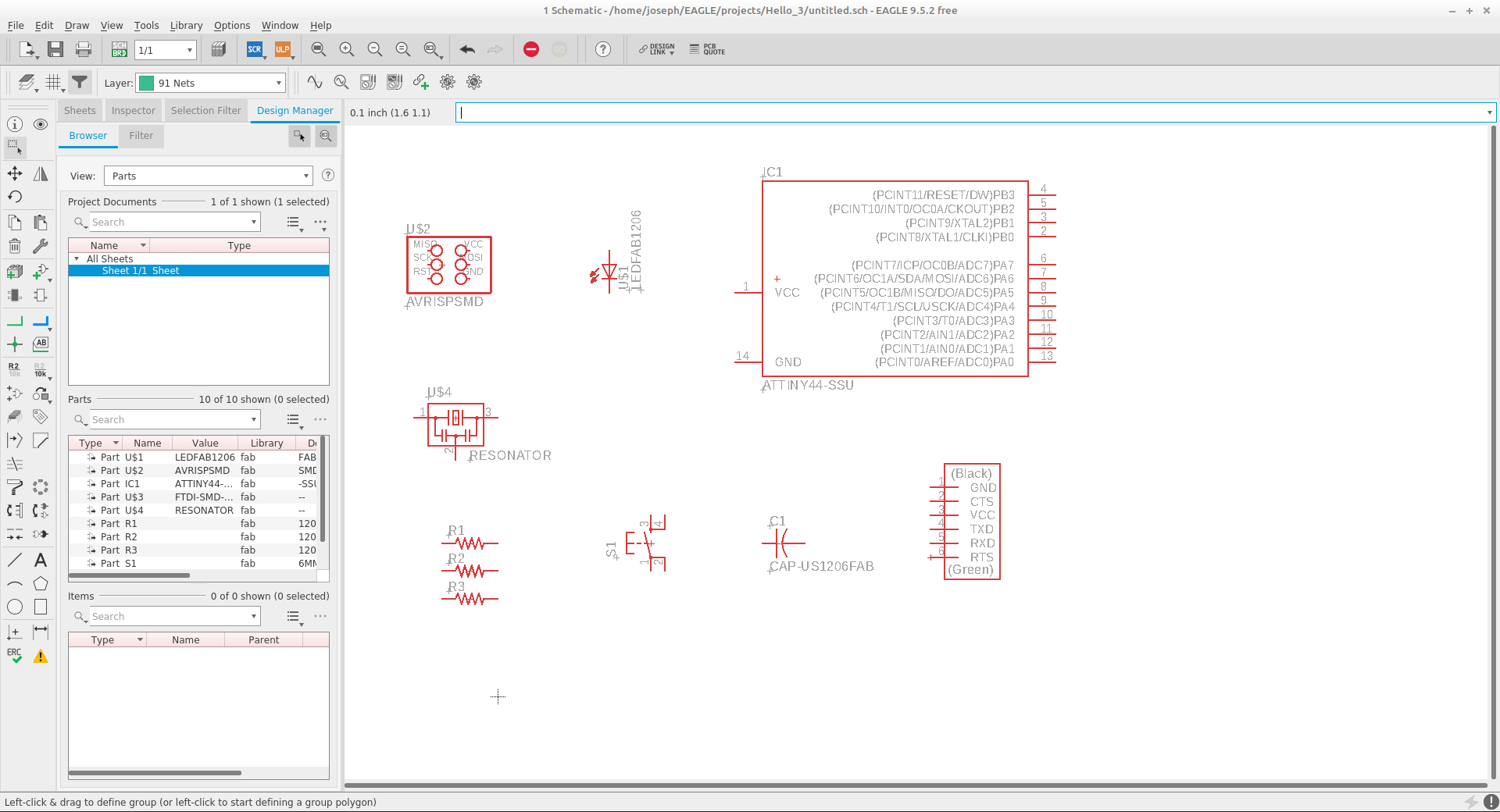
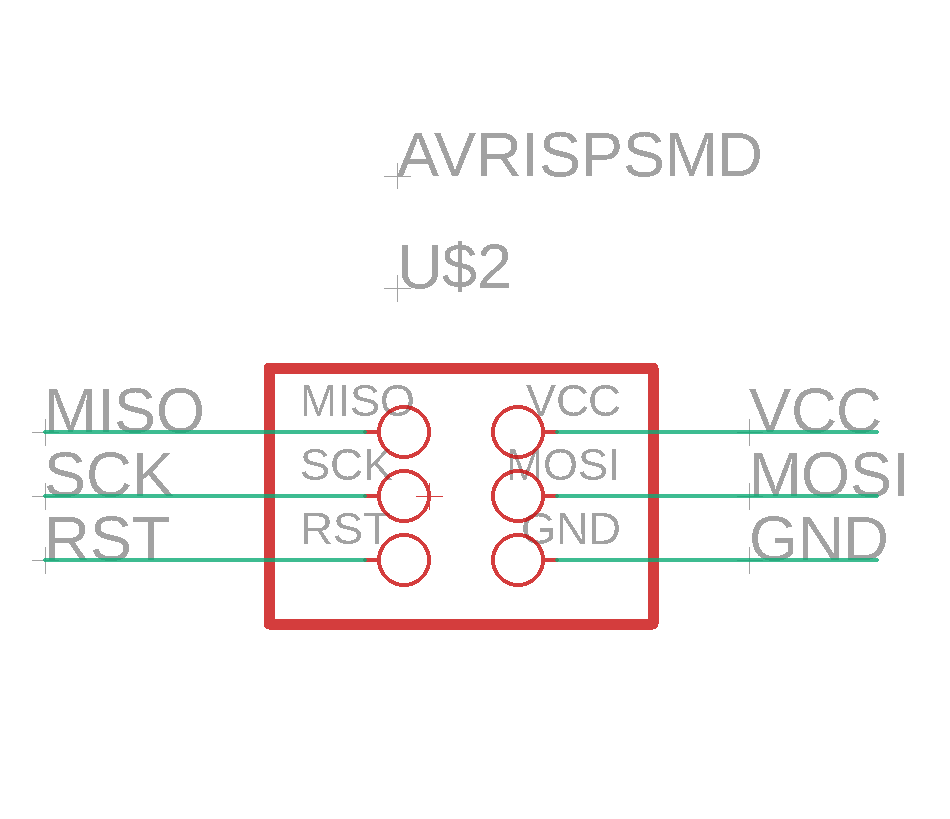
After adding all the components the next step will be to connect them using net and naming the components.


-
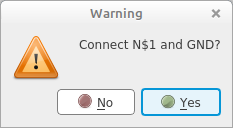
While connecting your components Eagle will confirm connection click yes to connect.
-
Here's a final schema of the Attiny44
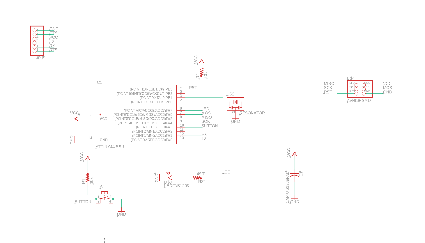
-
After finishing the schematic and connecting all the parts click on switch to board located on the top of the program

-
Your board will look like this at the beginning because it’s still not routed. Use move to move the parts relatively close to their connection points and rotate to get simple lines as much as possible, this will ease the routing process.
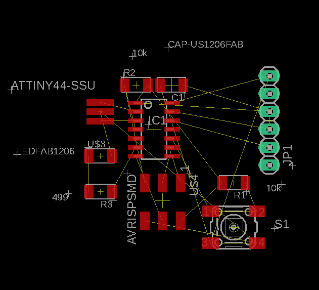
-
After moving the parts as relatively lined as possible- go to tools/ auto router. I found auto router very useful, I still didn’t use it on other schematics it’s a useful tool to help imagine the design possibilities. Since ill be designing the top layer of the board click n/a for the bottom layer.
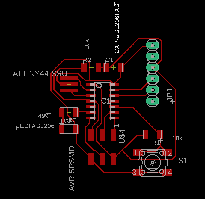
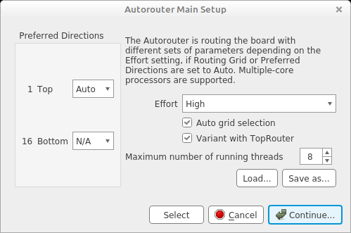
-
Run design rule file which was included with with fab library to check if the design is correct.

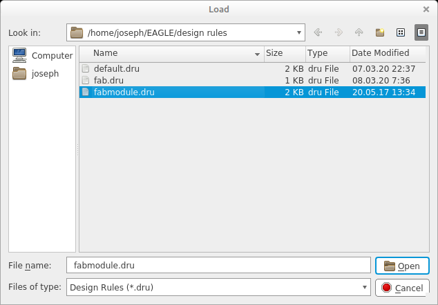
-
Export file at 500dpi, select monochrome and export. Crop image if needed.
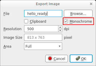
Results:
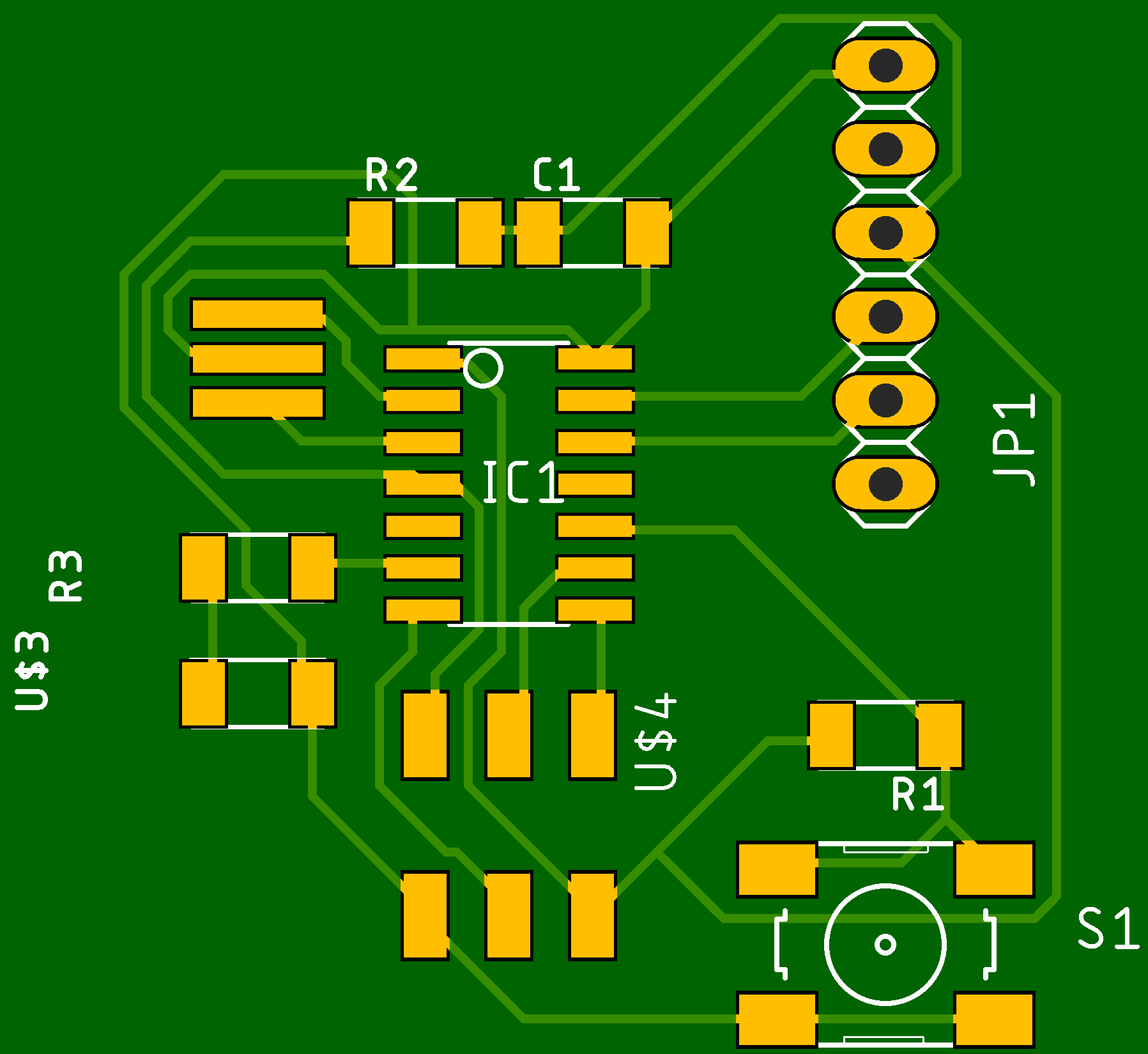
FAB Modules
We need to modify the file before using Fab Modules by using Gimp for getting clean traces and outlines by enlarge the canvas boarders by 20px and keep he image in the center.
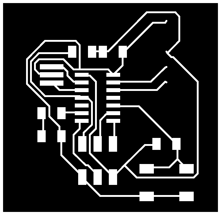
Traces
- Open the png.file in Gimp
- Click on image and select canvas size
- Add 20px on width and height and click on center then resize
- Click on image – flatten image.
- Export
Outline
Using the same file in Gimp.
- Select bucket tool.
- Fill in white traces in black, leave canvas border intact.
- Export.

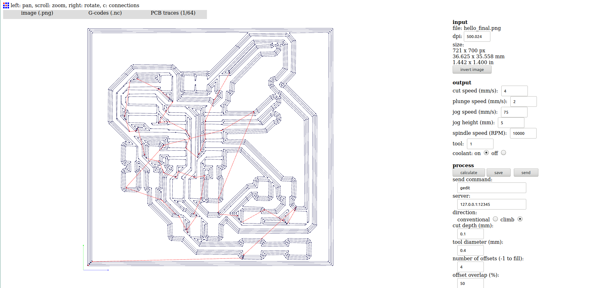
Using fab modules we’re going to generate tool paths for the milling process using G-code.
Generating Traces
- Select input - PNG
- Select output - G-codes
- Select process - PCB traces (1/64)
- Select Calculate
- Select Save
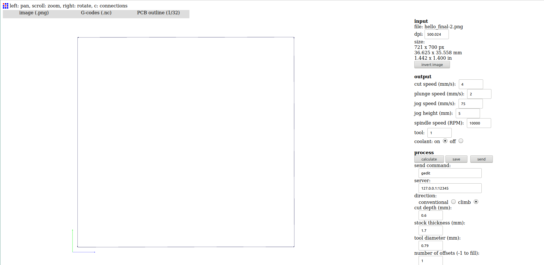
Generating Outline
- Select input - PNG
- Select output - G-codes
- Select process - PCB traces (1/32)
- Select Calculate
- Select Save
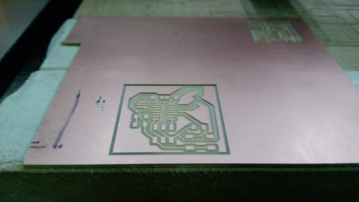
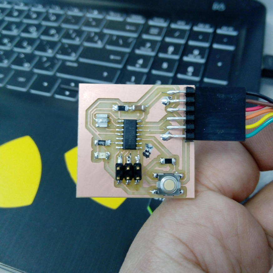
Results:
Conclusion
The tutorial on the fab academy page was very helpful since I didn’t know electronics well. The reason I liked the tutorial is that it explains step by step the process on EAGLE and allows you to check your PCB before taking further actions, it makes you go back to your design and check if there’s anything is missing and correct your design.
Design Files
| Name | Type |
|---|---|
| Hello Board | .brd |
| Hello Board Schematics | .sch |

This work is licensed under a Creative Commons Attribution-NonCommercial-NoDerivatives 4.0 International License.