Electronics Production
Using CAM “computer aided manufacturing” we can design, cut program and prototype either single sided or double sided PCB.
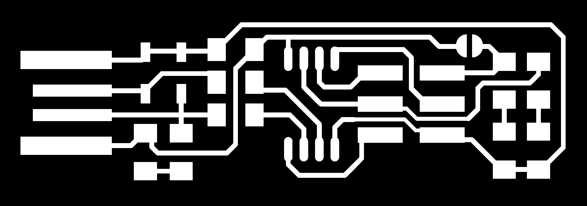
A milled PCB “printed circuit board” is a structure for microchips and electronic components. PCB are similar to brain structure where information moves from one point to another as a network of a city where there is roads, streets, highways similar to a city scape. This week I'll be milling and soldering a single layer PCB which consists of a solder mask, copper layer and a substrate.
FAB Tiny ISP
An ISP “in system programming” is a tool that is capable of programming logic devices, micro controllers and other embedded devices. The use of the ISP is for building and coding your own microchips and boards without having the need of a specialists or manufactures.
FAB Modules
Dowload ISP files the trace and cut files.

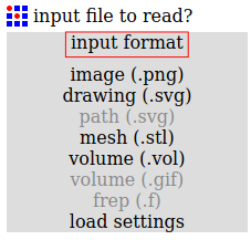
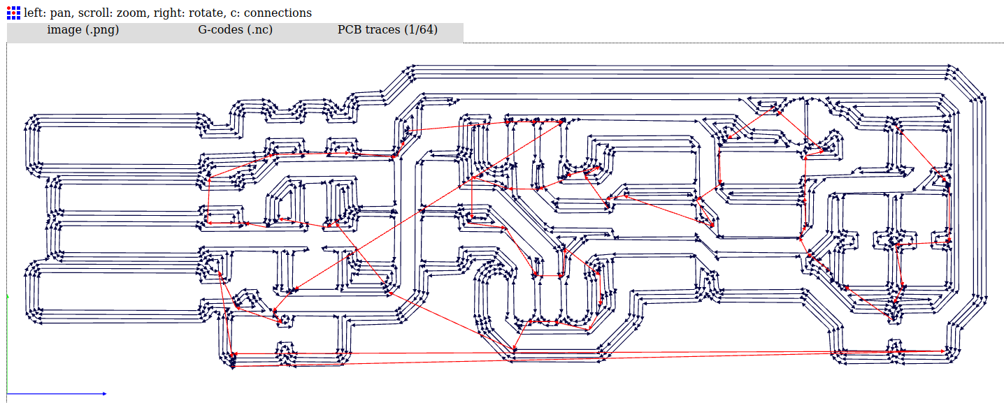
Using your browser go to the FAB Modules page and choose your input in this case we're uploading a .png file.
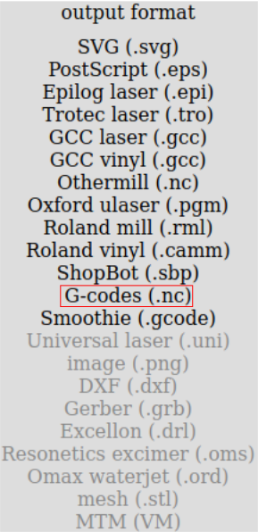
Select G-codes.
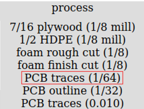
Choose the type of process for the mods to calculate, in this case we'll be tracing so choose 1/64 mill for tracing.
Click on calculate to calculate the tracing process and save the G-codes to your computer.
Repeat the same steps for the cut file by changing process from 1/64 to 1/32.
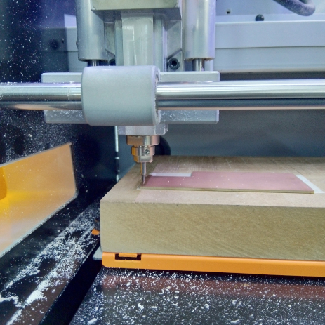
Roland SRM-20
The Roland SRM-20 is a compact desktop milling machine that has three axis it is capable of milling 2D/3D prototypes. It is capable to work on different types of materials such as modeling wax, wood, foam and PCBs. It’s a user friendly machine that comes with a computer software for adjusting and setting the machine.
Now that we have the G-codes on our computer we can start by setting up the milling machine to cut the PCB.
Read the operation manual.
Download and install the Roland SRM-20 V-Panel software to operate the machine.
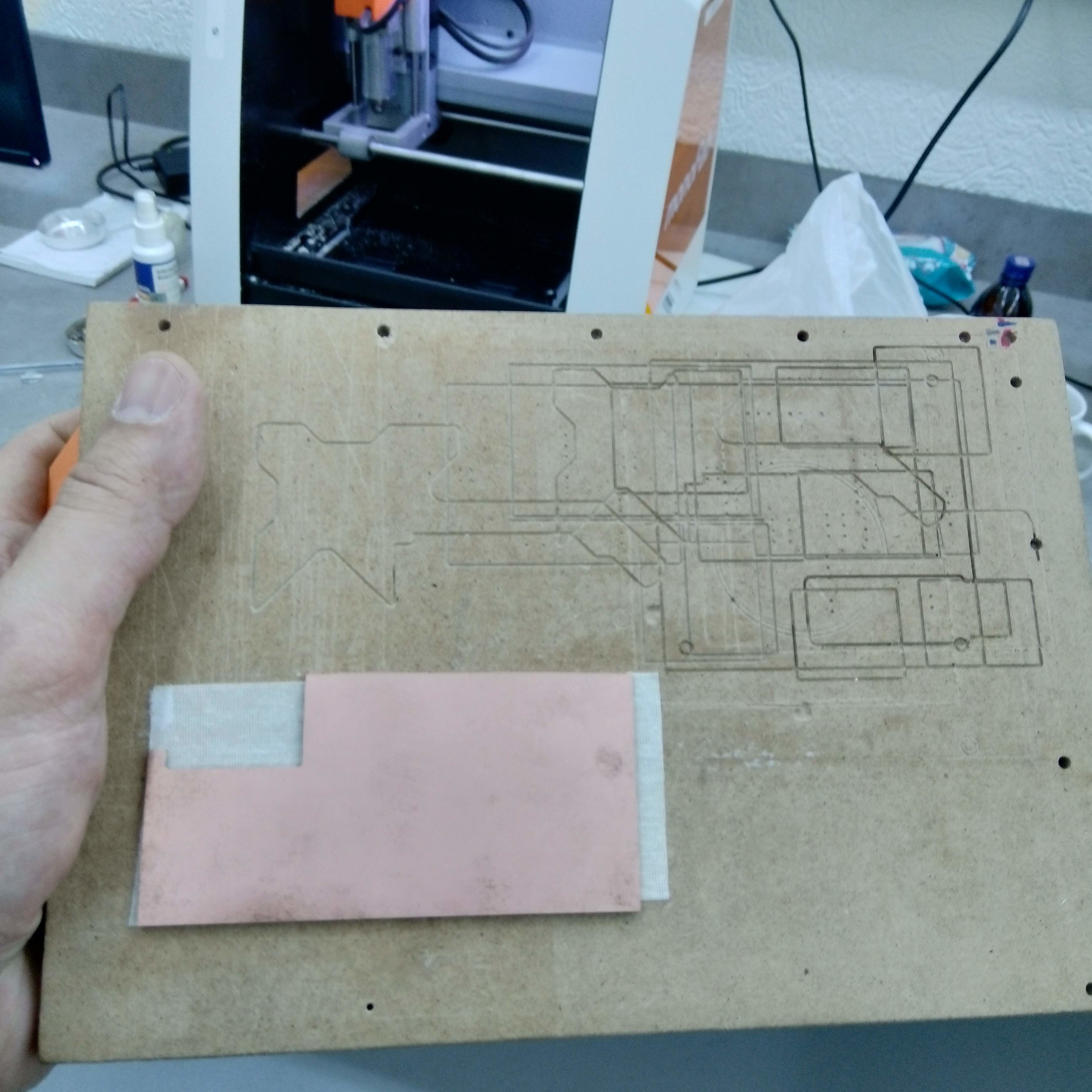
We need to stick our board well on the sacrifice board using double stick tape and ensure that it well fitted. I used to wood boards and coverd the pcb with a cloth and stood on it for about 3 minutes.
Tighten back the sacrifice board to the machine.
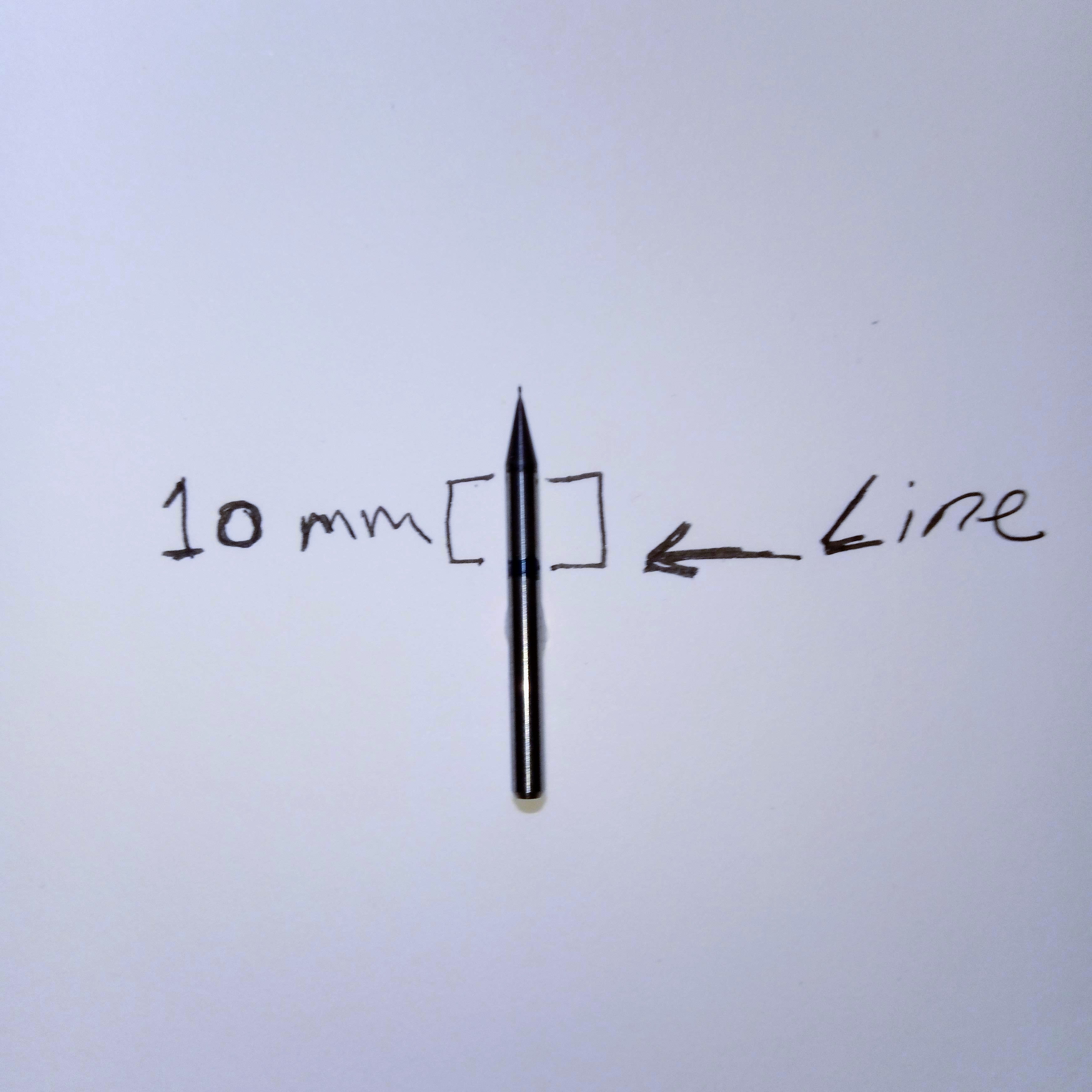
I used a technique where I measured the drill depth and marked a 10mm to aim the correct amount for the Z axes.
Install the 1/64 for milling the traces of the board and tighten it to the collet using the wrench provided.
V-Panel
The Vpanel is a dedicated software to run the machine so make sure it's installed and that the machine is on. Now that everything is set we can start by configuring the VPanel and start drilling.
Setting up the origin point for the X/Y/Z axis
A good tip I read is to warm up your machine for 10 minutes before doing anything. I think it's a good tip to check that everything is working.
For Setting up the origin point for X/Y axis you need to use the Vpanel XY cursors to set the origin point on the board, use a few of mm offset for a clean cut.
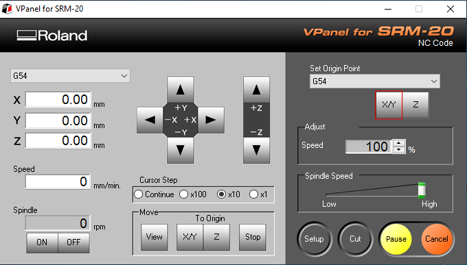
After setting the origin point click on the XY axis origin point on the Vpanel.
Now we need to set the Z axis and this is where I found that this technique works. Since I marked my drill I can see exactly where the 10 mm line is. I set the Z axis to the board and then loosen it.
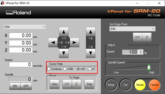
Now that the drill is free I set the Vpanel cursor step to x10 or x1 for and click along for a perfect 10mm aim and tighthen the drill.

Click on set origin for z axis.
G-code
G-code is a numerical programming language for controlling computer aided manufactuing to control automated machine tools. The G-codes is a map for the machine that tells the motors how fast to cut and where to move. Yes, it was first implimented in MIT. Now that the machine is set and ready for cutting the final step of this proccess is to load our generated G-Code to the Vpanel.
On the Vpanel click on cut.

Click on Add to add the G-codes.
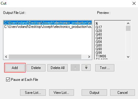
I will use pause on each file in this situation to switch the drill tip from 1/64 to 1/32 for cutting the board.
Click Output to commit.
Results:
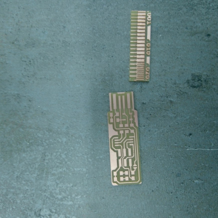
Note: Wash the board after cutting and aviod touching surface, touching the surface can leave stains and oils so keep it clean for good soldering results.
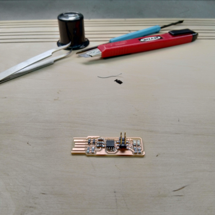
Soldering
To solder is to bond two metals together using high temperatures, soldering takes some time to master and I found it to be a meditative job. Warming up the point where you want to solder using iron is a good start, I found it useful for working with small microchips, by applying a bit of solder just to cover the surface and later finish by adding a bit more to solidify the parts together. For microchips with feet it’s good to top foot from one side and the lower foot from the other side to strengthen the solder. My first try was not successful when it came to programming the ISP I tried changing the diodes and checked the ISP with our node to figure out the problem. Everything seemed to be soldered fine and we spent allot of time trying to figure what was wrong, at the end we decided to solder another board and it was successfully programmed.
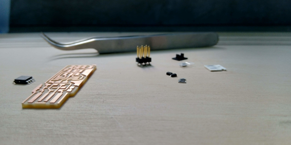
List of items
- 1x ATtiny45 or ATtiny85
- 2x 1kΩ resistors
- 2x 499Ω resistors
- 2x 49Ω resistors
- 2x 3.3v zener diodes
- 1x red LED
- 1x green LED
- 1x 100nF capacitor
- 1x 2x3 pin header
Result:
Software Installation
For this board we need to setup the development environment by installing the AVR.
Using the command line: sudo apt-get install avrdude gcc-avr avr-libc make
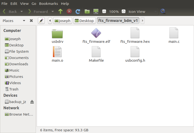
Download the firmware source code and cd into the directory and run make.
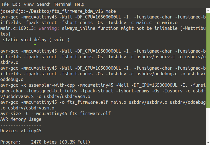
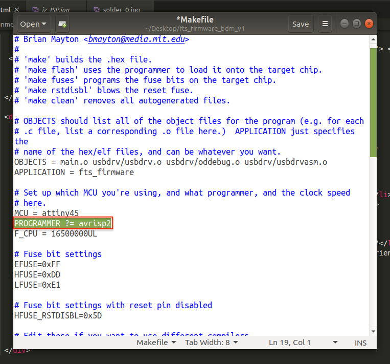
Edit the Makefile by changing the line PROGRAMMER ?= usbtiny to PROGRAMMER ?= avrisp2 and run command gedit
Save the file and plug in the board to the usb port using a short extension cable, the LED must lit up if soldered correctly.
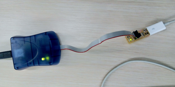
Connnect programmer to the ISP head "ISP pin heasd 1 must be at at the right orientation check diagram and plastic head".
Run make flash (to erase the chip and program with ".hex" file).
Run make fuses command.
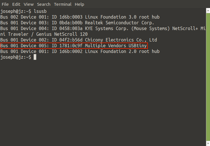
Run lsusb to check if the device is listed "Multiple Vendors USBtiny"
By running these last two step we seal the microchip from being programmed again.
Run make rstdisbl
Run avrdude
Blow the reset fuse!
Conclusion
The phases that we went through from milling to soldering to testing and programming were fed to us without knowing what we’re eating. I enjoyed the process of bringing these new abilities together.

This work is licensed under a Creative Commons Attribution-NonCommercial-NoDerivatives 4.0 International License.