Computer Controlled Cutting
Starting up with this assigmnet I have leared a new term called "RTFM".
The user manual is important to read to know how to use the machine and It’s a good start to learn about what the machine can or cannot do. Safety comes first! so make sure that the surroundings of the printer is dust free, clean and far from falling objects.
Disconnect the printer if you’re not using it for long and keep your hands away while the machine is printing. Before printing anything I need to load the material correctly and initiate a test cut to determine how much force is needed to perfectly cut out a shape from the material.
Note: “The material used must be clean, dust free and flat! Flatten and clean the material before use.”
ROLAND GX-24
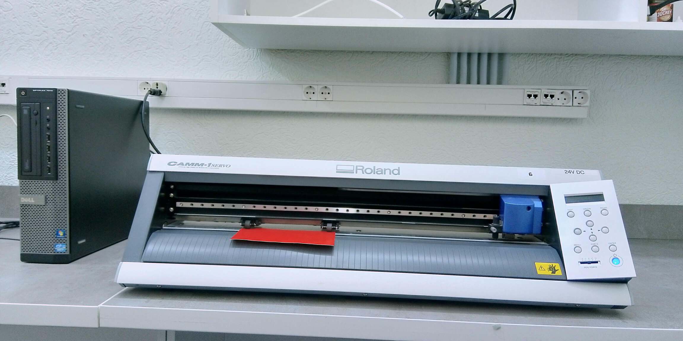
Loading the material
- Load the material into the ROLAND GX-24 by lowering the loading level located at the back of the printer.
- There are grits on the printer that are guidelines for the printer to determine where it will be cutting.
- Place the material so it’s aligned with the grits.
- Place the pinch rollers on their verification marks.
- Align the material so it’s parallel with the guidelines of the printer.
- Raise the loading level to lock on the material.
The needle was pre-installed and ready to go, but we took a moment and investigated how the needle is loaded and functions.
Test cut
The test cut is the most important step taken in the cutting process because we determine how much force is needed to cut through the material. Make sure that the correct drivers are installed and that connection to the vinyl cutter are right.
- Turn on the printer.
- Set the pen force to (0) located on the printer.
- On printer display choose the type of sheet you’ll be using and press enter.
- The cartridge moves, determines and shows the dimensions of the piece on the display.
- Press the test button for two seconds and the machine should commit the test.
- Press the down button on the printer to feed the piece towards you.
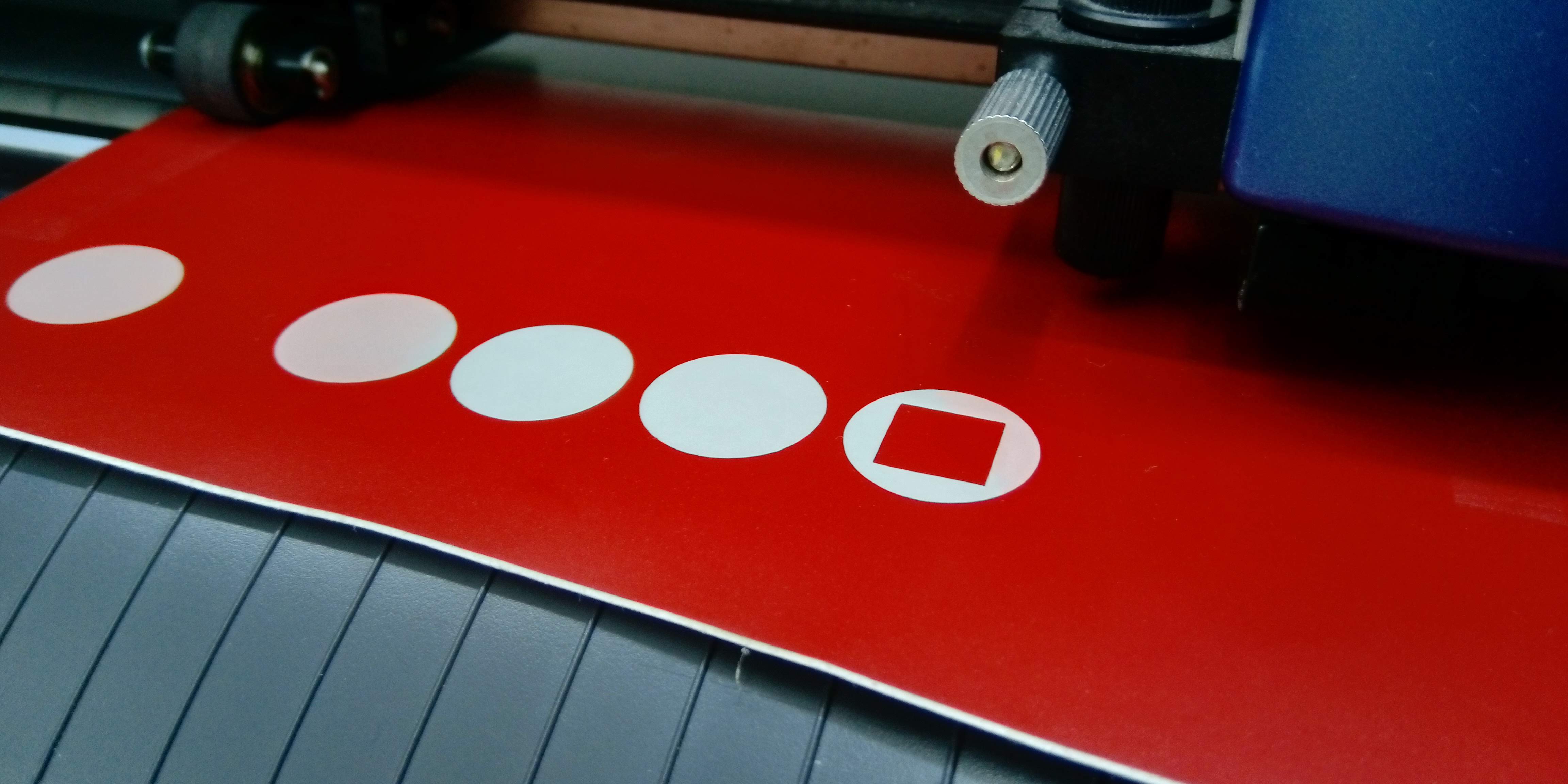
2th the rectangle, the force was set to 50 GF.
I repeated the process to do another test with 55 GF and the circle came off clean.
To change the force of the you need to:
- Press the force button located on the printer.
- Using the left and right arrow to increase or decrease value.
- Press enter.
- Using the arrows you can locate the next cut. “Keep it close to the first location you tested.”
- Press the test button for two seconds again
Result:
Cutting
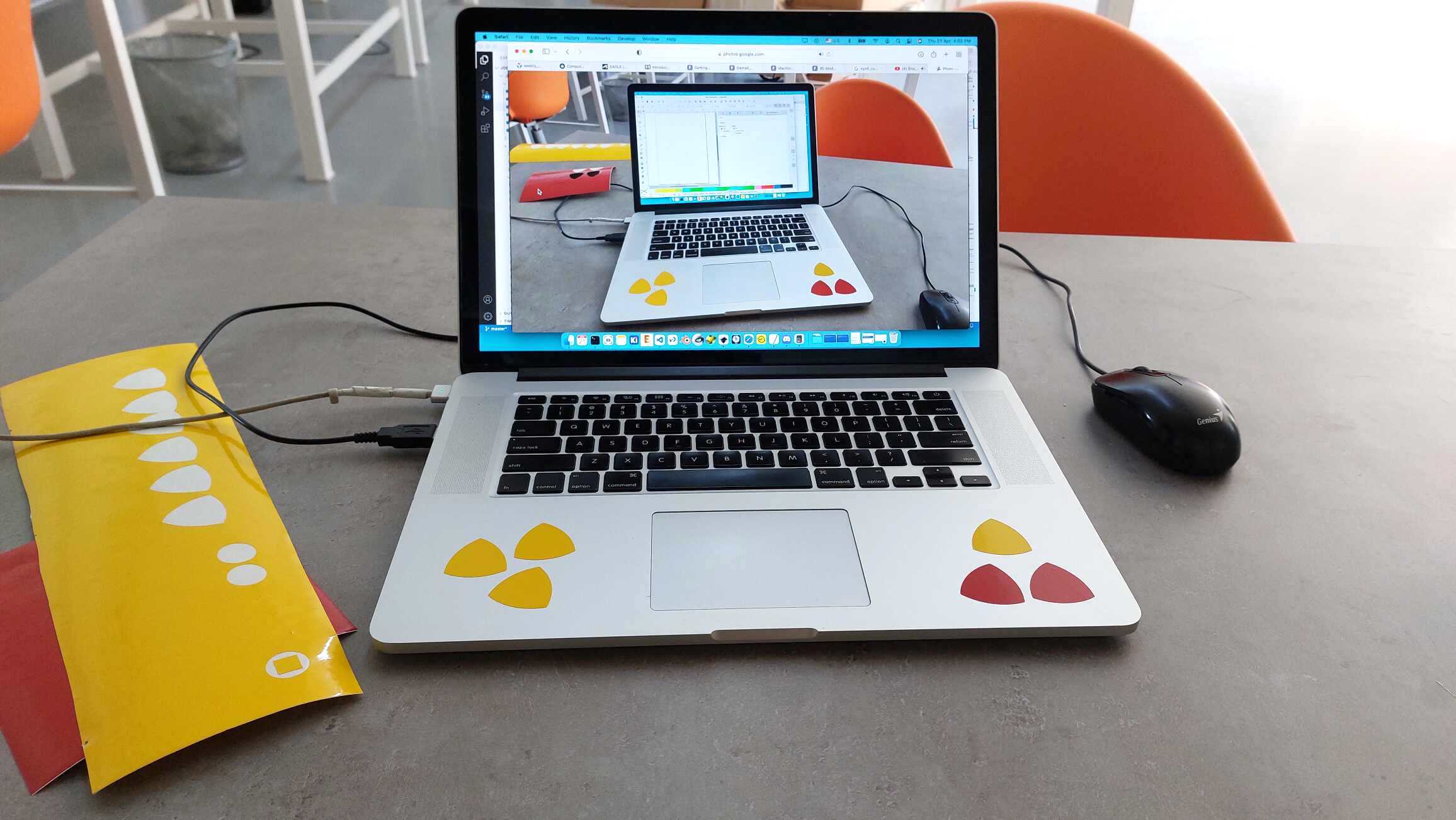
For cutting I’m going to use the triangle I designed on the computer aided design week.
-
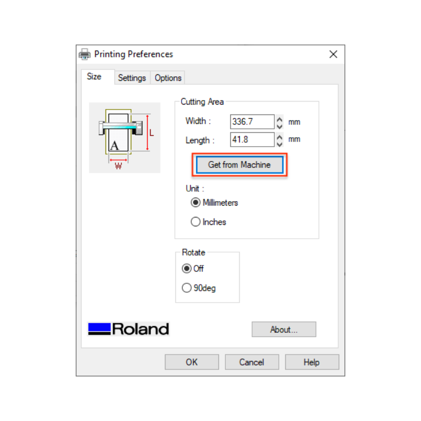
First we need to set the height and width of the paper we get the dimentions from the printer once we load the paper.
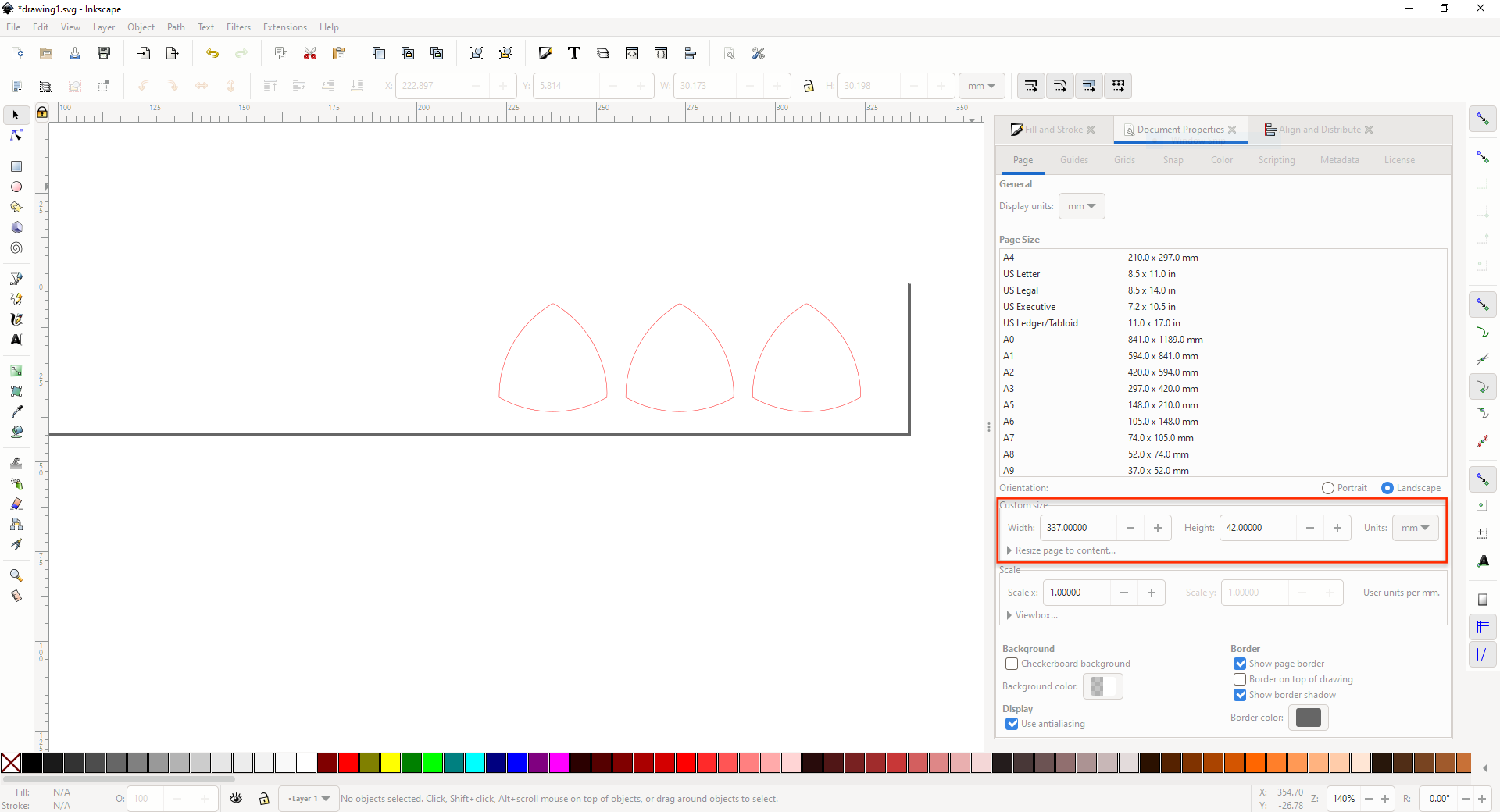
-
Since we are cutting we only going to need the strokes, set stroke width to Hairline.
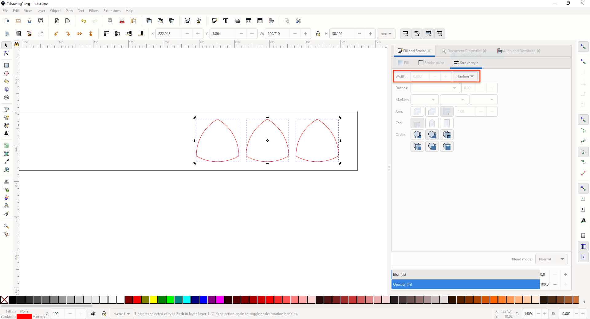
-
For printing on the correct dimentions go to printing prefrecences and click on get from machine and then print.
Result:
Parametric Press-Fit Construction Kit
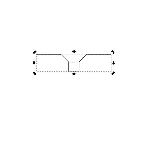
Inkscape
For creating the fit kit I went through the Fab Academy tutorial I find them very useful and helpful.
- Start by drawing a square.
- Draw a smaller rectangle and center align it with the square.
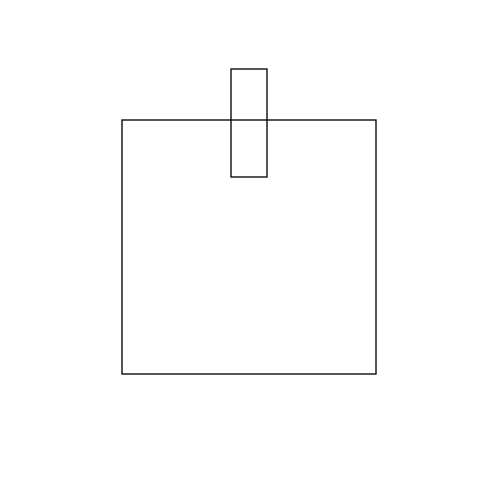
- Click on the rectangle and go to: object/ raise to top.
- Select both object and go to: path/ difference.
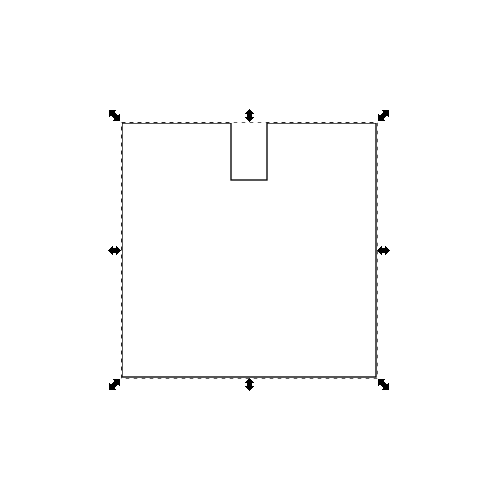
- Create a square and object/ transform 45 degrees and overlay it on the offset we created.
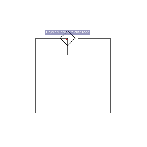
- Use snapping to lay the square in the middle of the intersecting object.

- Select both objects and go to: path/ difference.
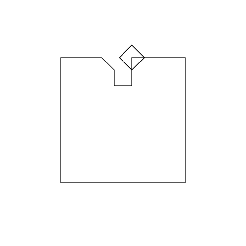
- Repeat step 5,6 for other side of the object.
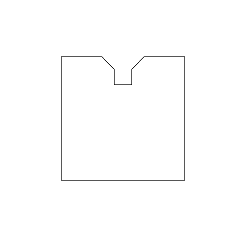
- Select object go to: path/ object to path.
- Select nodes and then click on break path.

- Ctrl – Shift – K to commit the function.
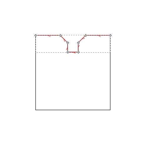
- With this part i'll be able to create different shapes for my press kit.
Results:
OpenSCAD
During last weeks recitment our regional mentor Ohad asked me to check a 3D modeling software called OpenScad. OpenScad works on code, making all the parameters entered symmetric. I found plenty of information regarding this beautiful software right in it’s help menus cheat sheet. Going through the cheat sheet you can find plenty of information and video tutorials, what I really liked about this software is it’s simplicity and precision.
I'm using Ubuntu and OpenScad doesn't support it’s newer versions due to build failures but you can download OpenScad PPA repositories which work just fine.
Installation:
- sudo add-apt-repository ppa:openscad/releases.6
- open software update and edit OpenScad repositories and change distribution from cosmic to bionic.
- sudo apt-get update
- sudo apt-get install openscad
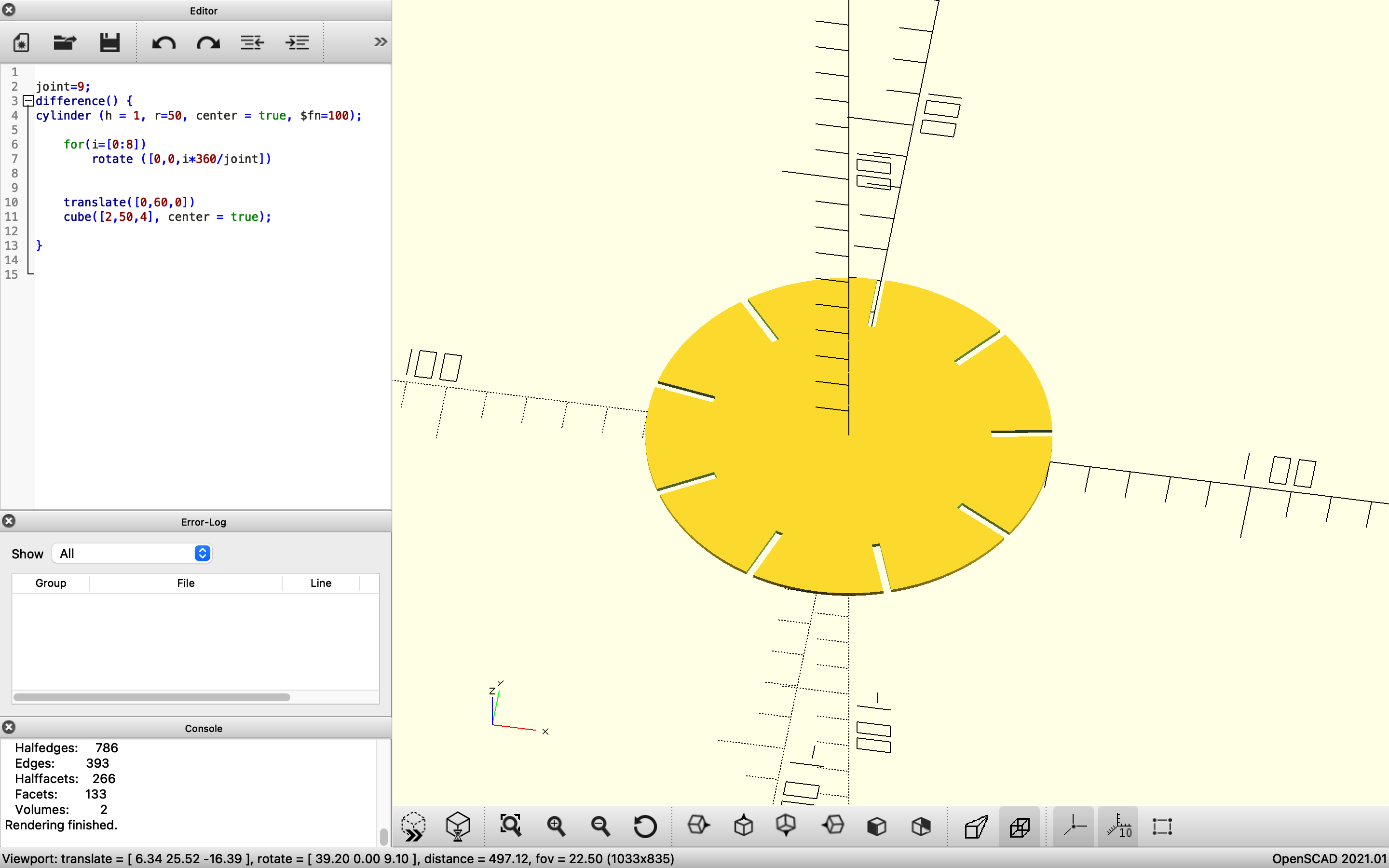
Code
joint=8;
difference() {
cylinder (h = 1, r=50, center = true, $fn=100);

    for(i=[0:512])
        rotate ([0,0,i*360/joint])


    translate([0,60,0])
    cube([2,50,4], center = true);

}
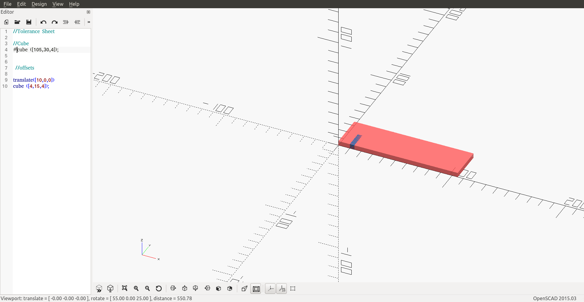
Tolerance Sheet
After doing a couple of tutorials I got a picture of what I need to create a tolerance test sheet.
I used simple commands to create a test comb, the commands I used are cube, translate and difference.
- I started by creating the cube and setting the dimensions of the rectangle.
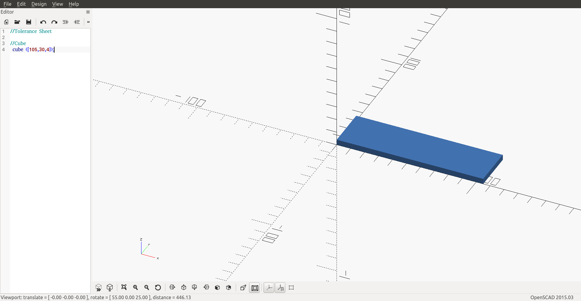
- Creating another object to define it’s dimension - offset @ 4 mm.
- Duplicating the cubes and dropping the offset @ 3.60 mm
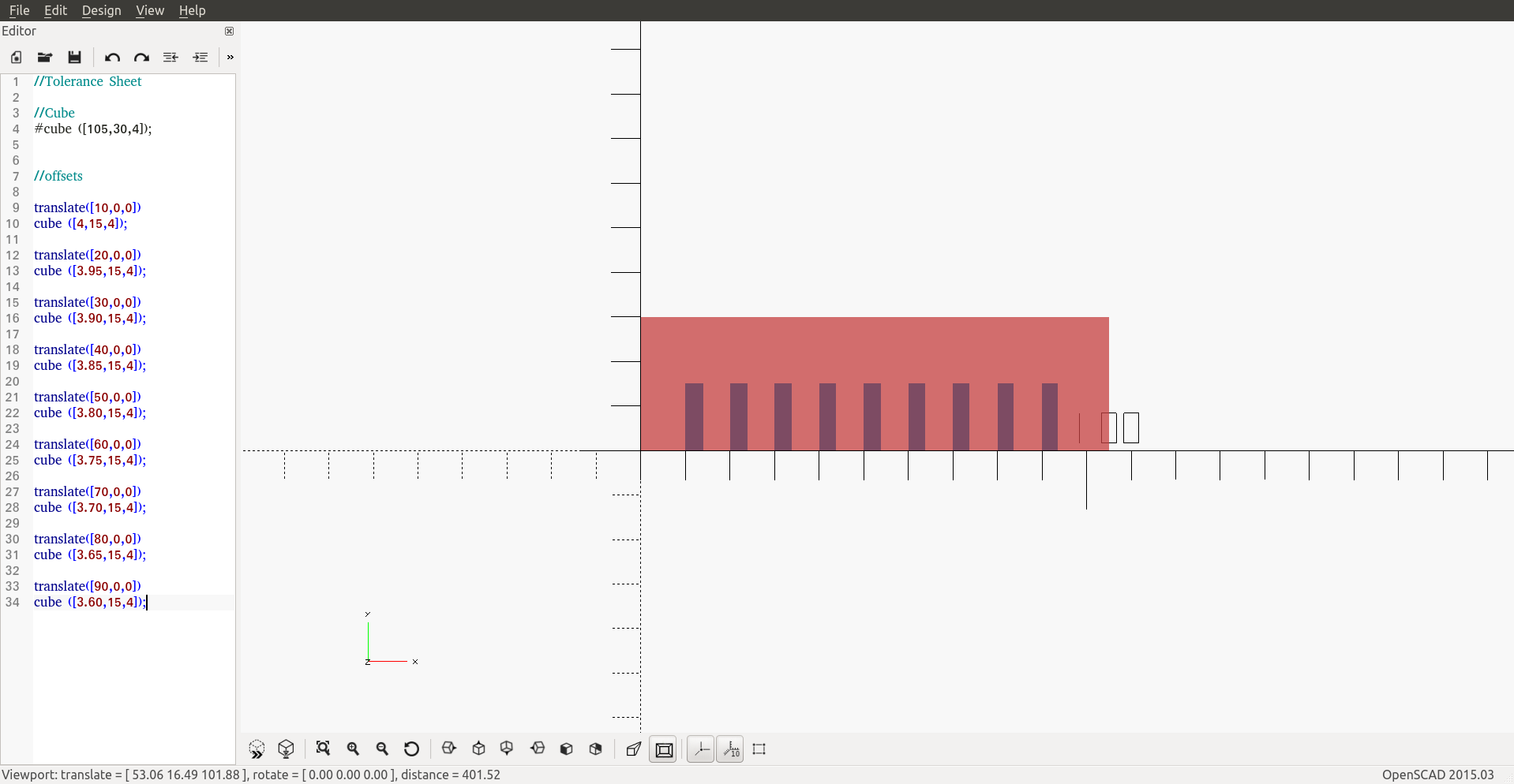
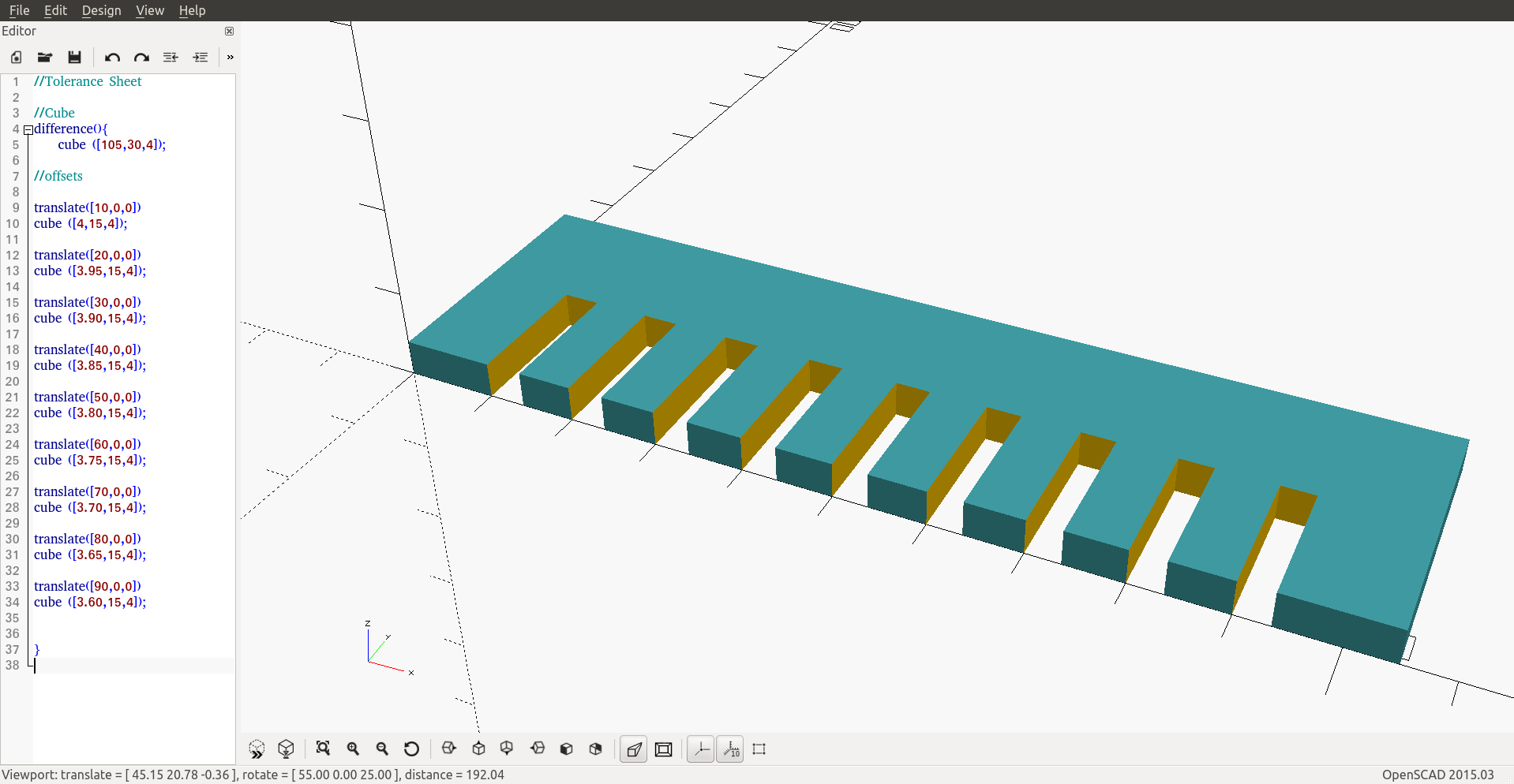
- Adding the command “difference” to subtract the from the primary object.
Code
//Tolerance Sheet

//Cube
difference(){
    cube ([105,30,4]);

    //offsets

    translate([10,0,0])
    cube([4,15,4]);

    translate([20,0,0])
    cube([3.95,15,4]);

    translate([30,0,0])
    cube([3.90,15,4]);

    translate([40,0,0])
    cube([3.85,15,4]);

    translate([50,0,0])
    cube([3.80,15,4]);

    translate([60,0,0])
    cube([3.75,15,4]);

    translate([70,0,0])
    cube([3.70,15,4]);

    translate([80,0,0])
    cube([3.65,15,4]);

    translate([90,0,0])
    cube([3.60,15,4]);

}
Note:
Use this command to export your files to DXF projection(cut=false) import("/Users/josephzakarian/desktop/ts.stl");
this is a good documentation OpenSCAD to DXF on how to convert your OpenSCAD files.
Laser Cutting
The most important thing is safety! The laser system uses high intensity beam light that can generate high temperatures when it comes into contact with materials being engraves or cut. Some materials are highly flammable when using never keep the laser unattended, keep the area around the machine clean, always keep maintained and have a fire extinguisher close to the machine. Read the Epilog Mini Helix - 40 Watt manual before use.
Group Assignment
Testing the lasercutter’s focus, power, speed and frequency rate using cardboard. knowing the thickness and type of the material will help us determine the speed and power recommended to cut or engrave the material. If you're using the 40 Watt - Epilog Mini/Helix open the owners manual to page: 197 for speed and power recommendations.
The thickness of the carbboard varies from 3.85cm - 4.00cm.
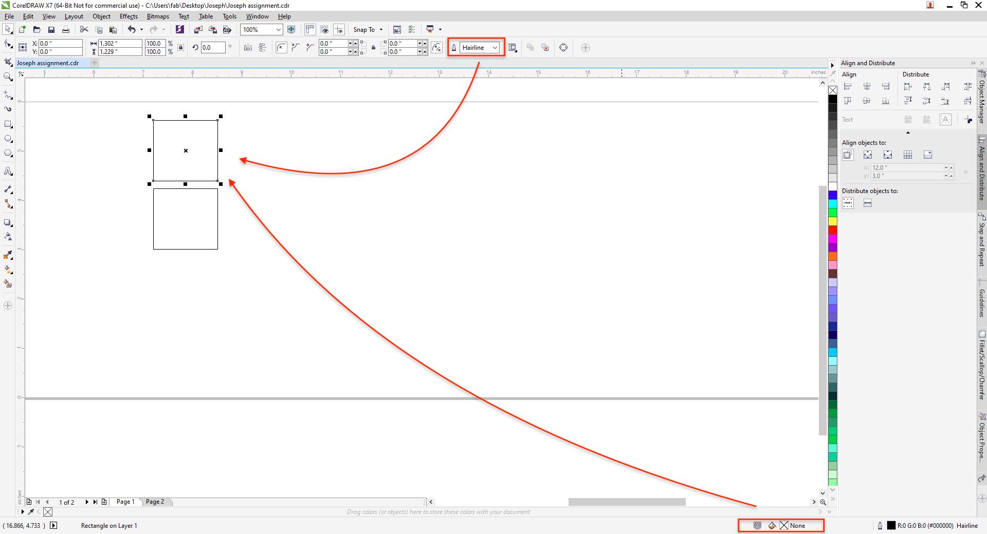
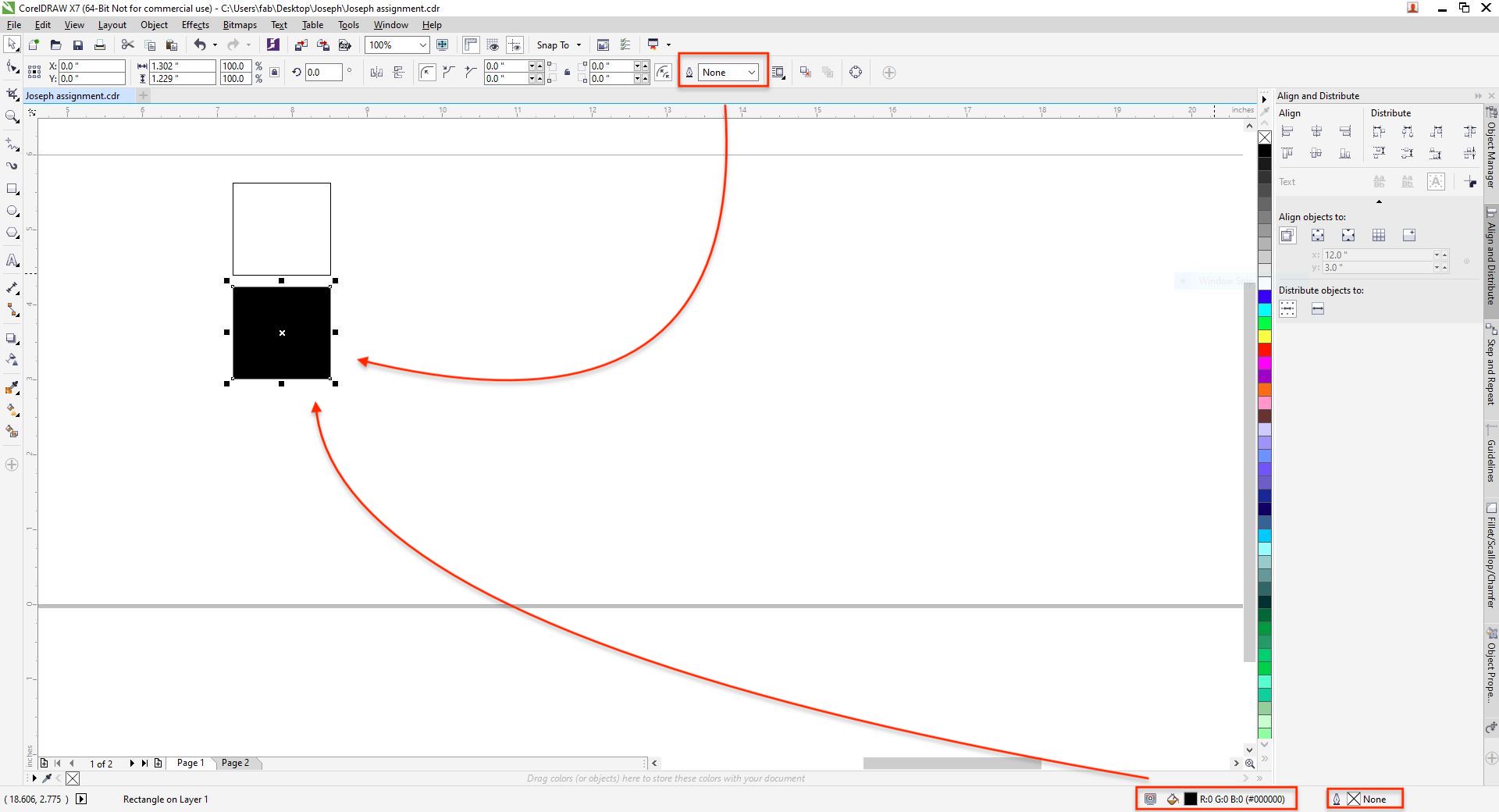
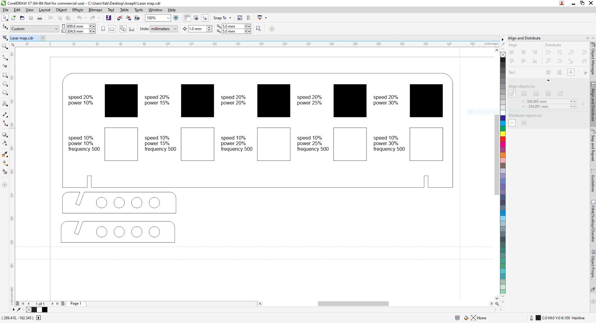
We want to create a range of tests with speed, power and frequency by drawing an object and values, a test sheet. For cuting an object you need to select the outline width to Hairline and for engraving by selecting a Solid Fill to the object.
Hairline, no fill for vector cutting...
 Solid fill, no hairline for engraving...
Quick Start
Test Sheet
-
Turn on the power and wait for a "Beep".
-
Load the material to printer alligned with the rulers on the upper corner.
-
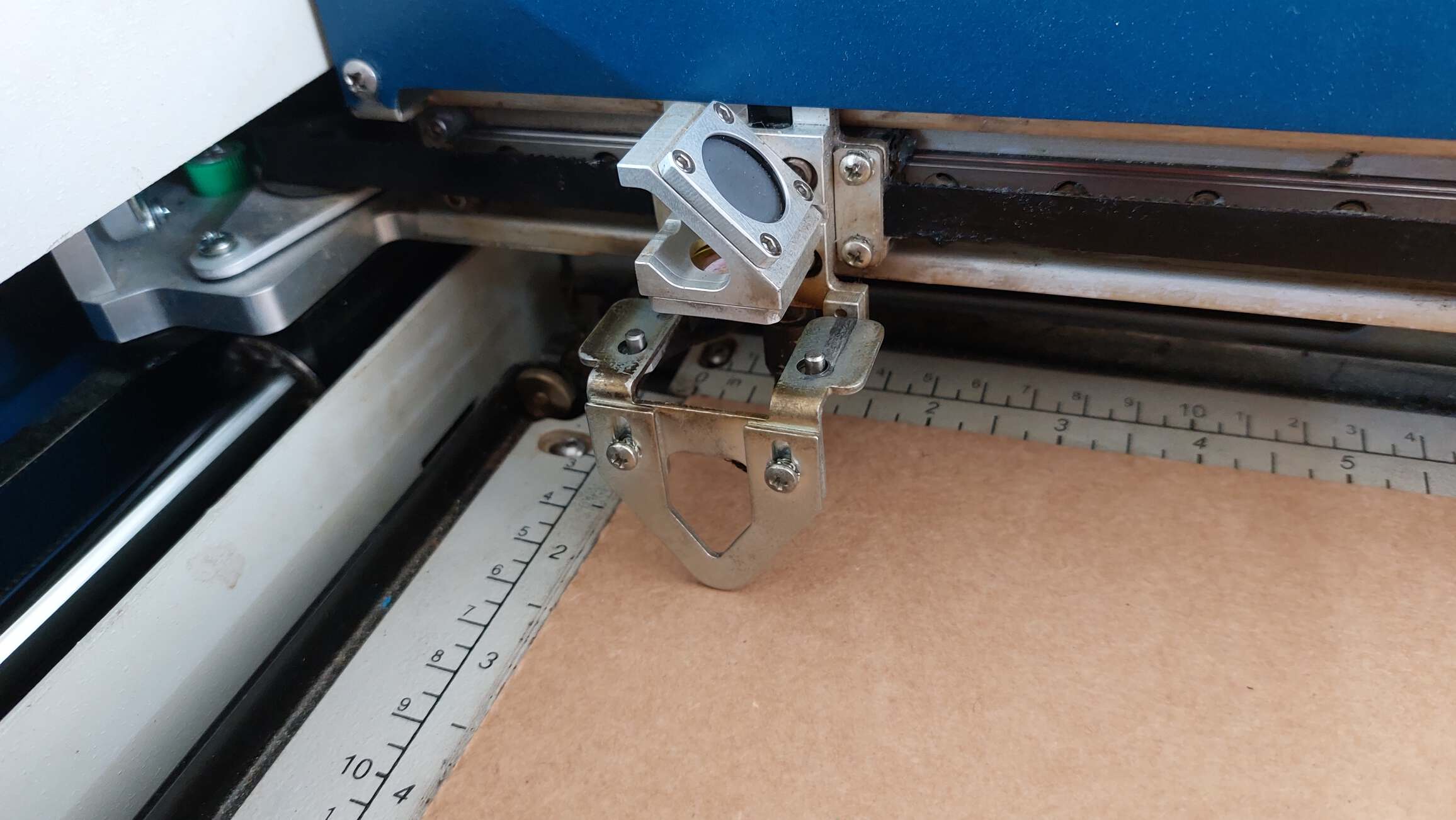
Using the Manual Focus Gauge we need to manually set the focusing point of the laser to have clean cuts and results, on printer control panel select focus and by using the arrows on the panel make the triangle close to the material, once done flip back the gauge.
-
Turn on the exhaust and filter.
-
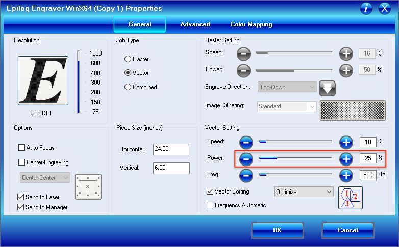
Close the door and on your software go File, Print select your printer then click on Preferences.
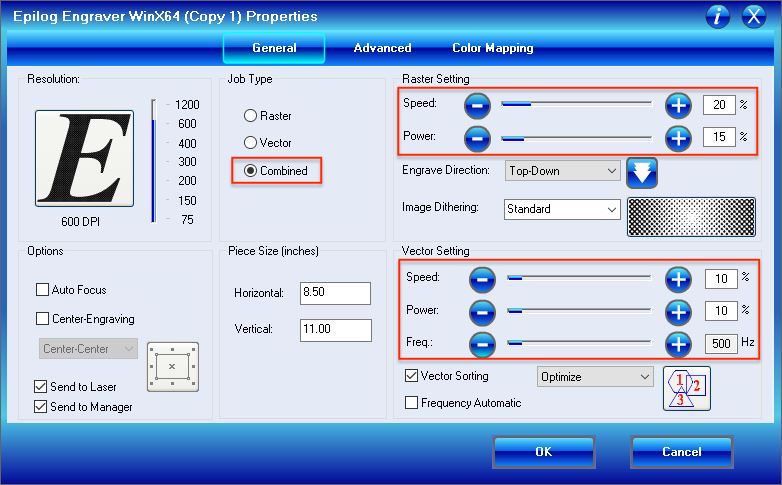
-
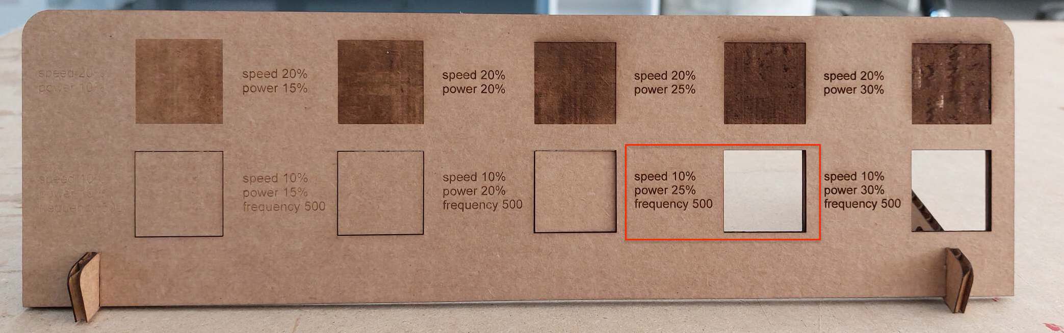
By changing the values from low to high, this is the result we got which will help us determine the power, speed and frequency used.
By adding the values to Corel Draw one by one we were able to determine the right power for the material.
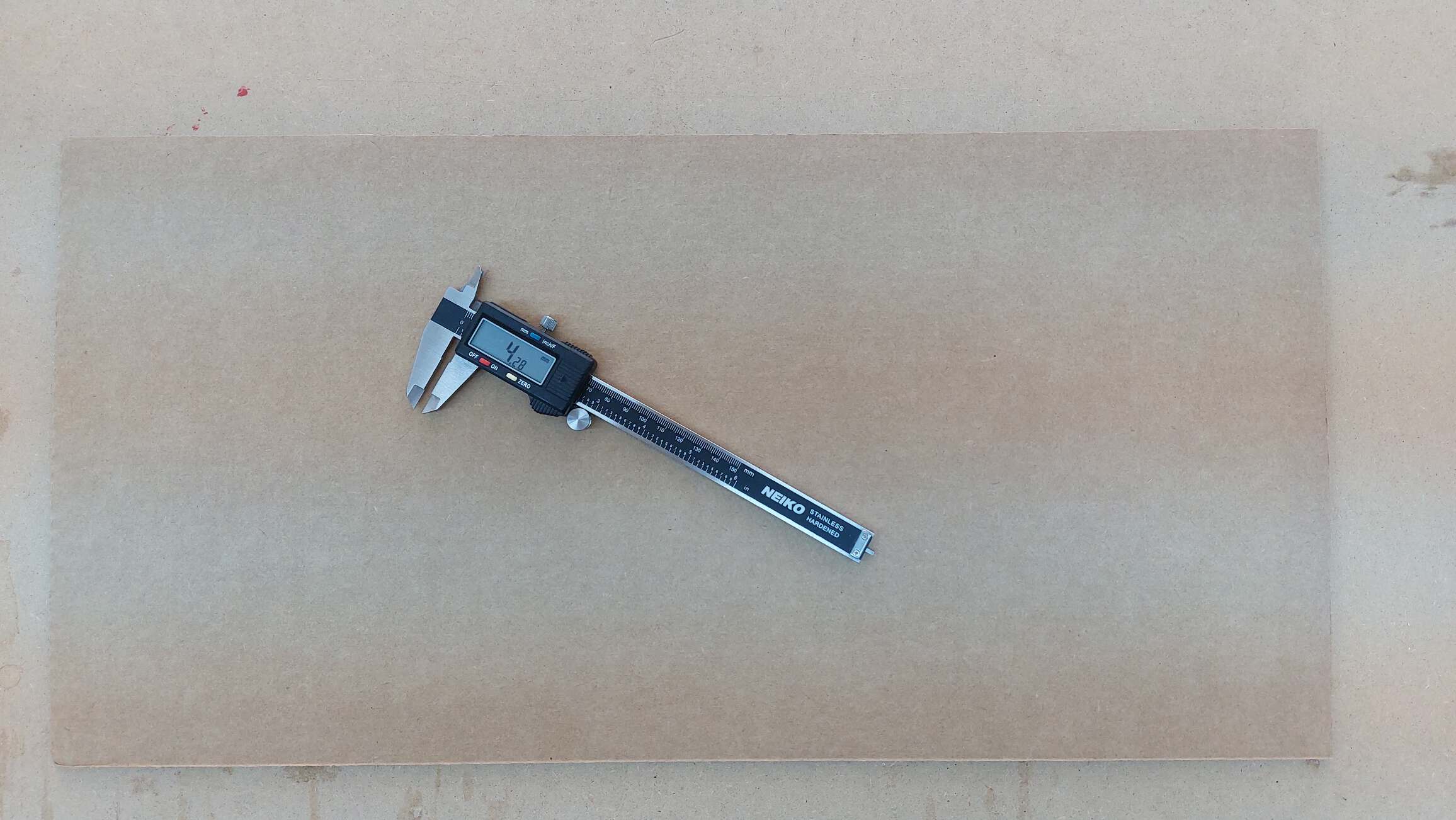
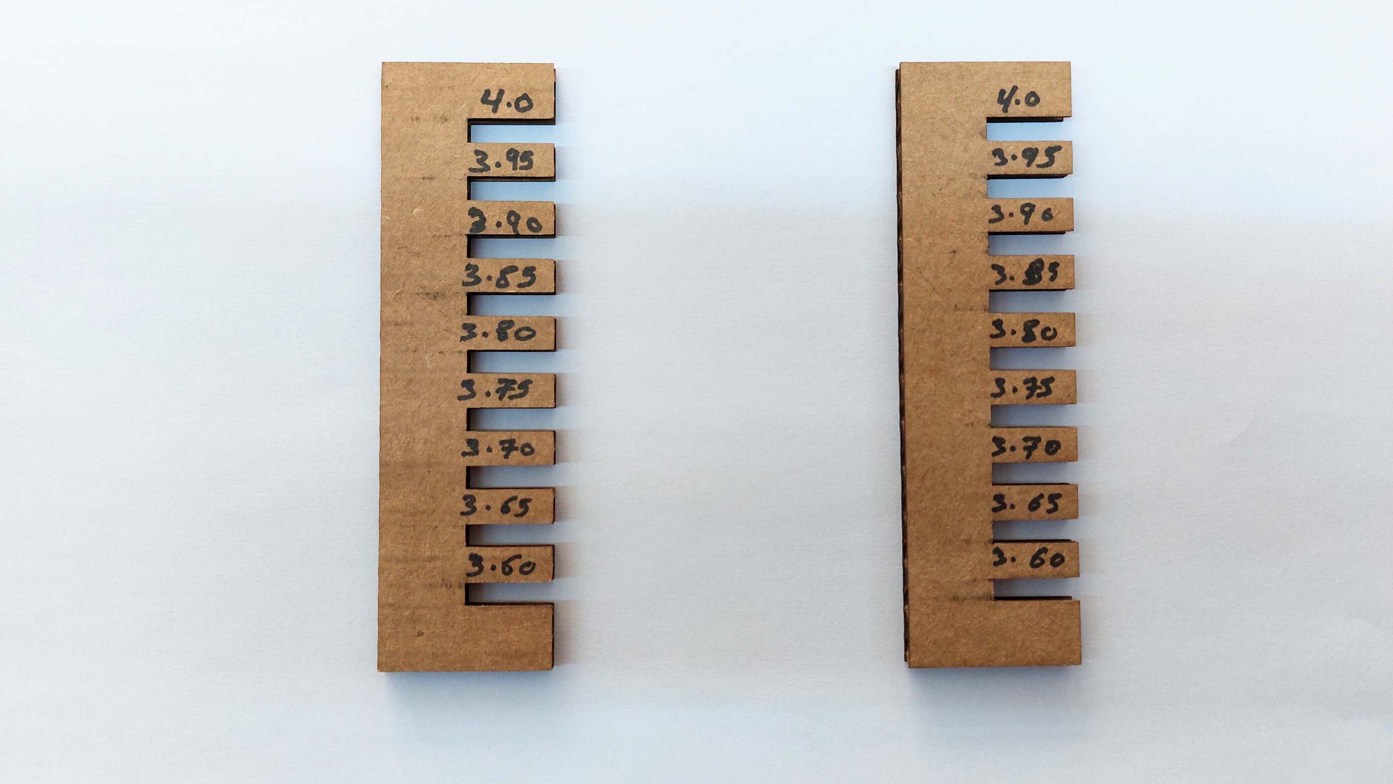
Tolerance Sheet
The after cutting the sheet which I designed beforehand on OpenSCAD we found out this the value of 3.60 mm is the the best overall because it fit perfectly, I will use this number for my press fit kit.
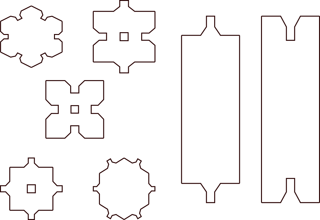
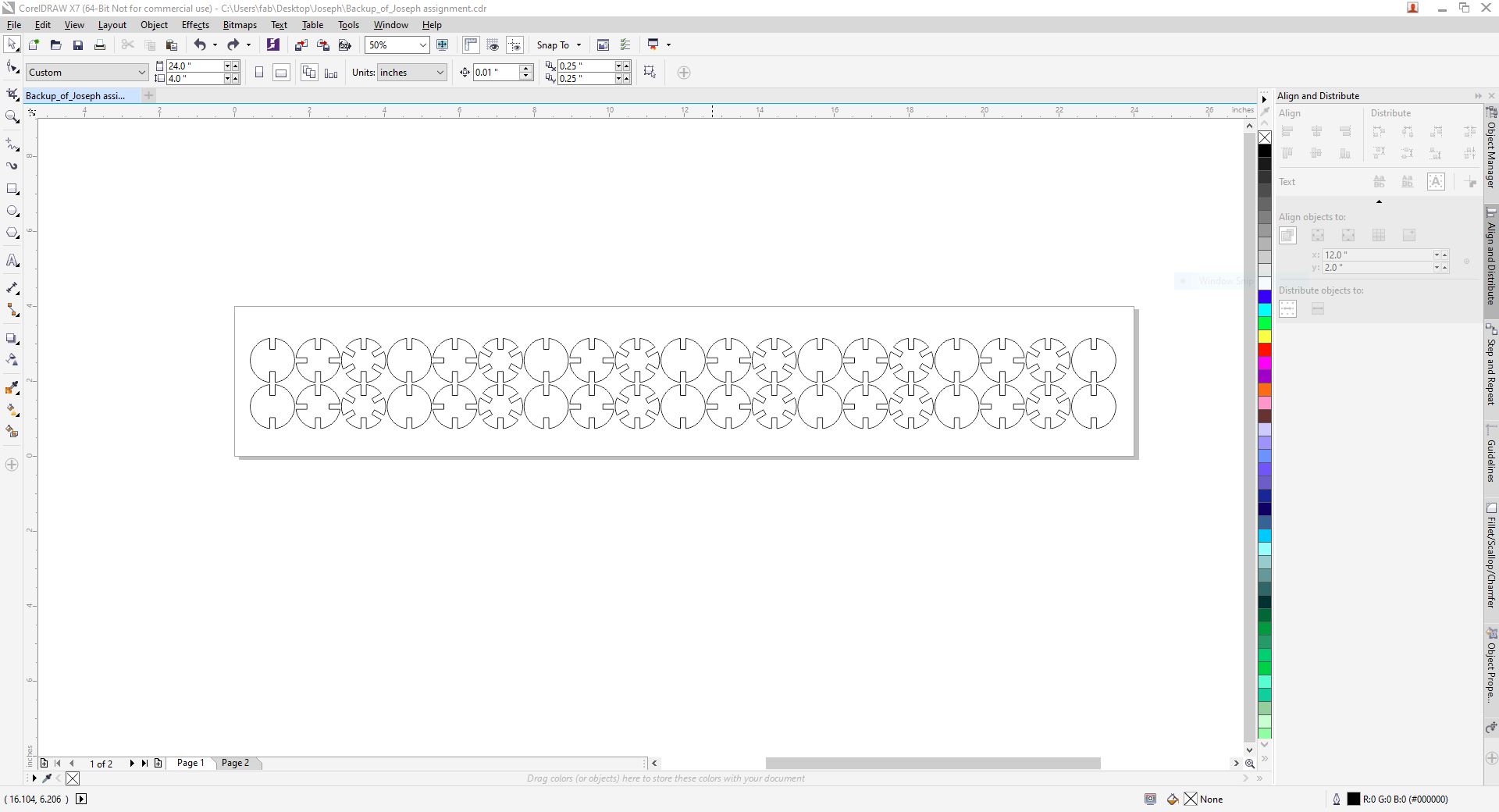
Press Fit Kit
Here are the shapes I created on OpenSCAD imported on Corel and aligned accordingly.
-
The first try was not successful because I didn't re-focusing the gauge. always refocus the printer even if you’re using the same material.
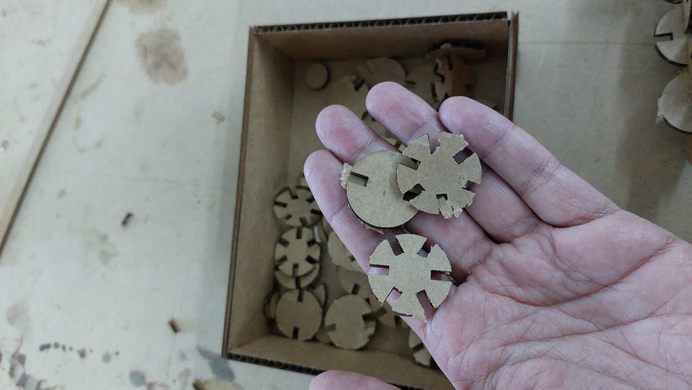
-
I'll go through the same process again, but before cutting the whole board I did a test and found out that I need to increase the power by 5% and found the results to be excellent.
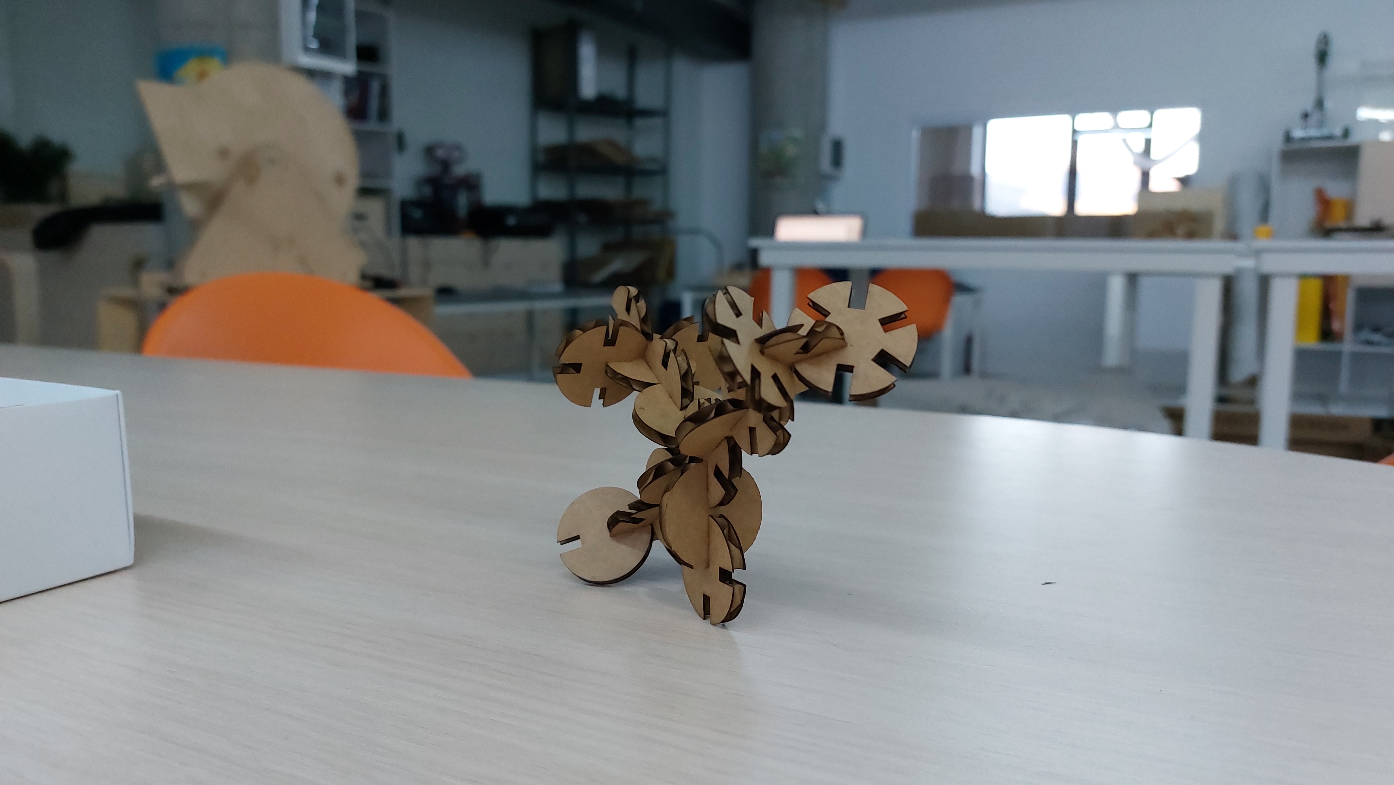
Hero Shot
Conclusion
Going through the lab machines I found the laser cutter to be on top of the list favorite machine due to its speed and precision. These are great machines that can bring ideas to reality. The process from starting with a parametric 2D object on your computer and having that file as a real 3D object is the most exciting part. Getting to know more about open-source CAD softwares made me think twice about paid softwares. Coding an object on OpenSCAD without having a background in coding is a great way to learn coding “fact”.
Design Files
| File | Type |
|---|---|
| Tolerance Sheet | .scad |
| Press Fit Kit - OpenSCAD | .scad |
| Inkscape - Press Fit Kit | .FCStd |

This work is licensed under a Creative Commons Attribution-NonCommercial-NoDerivatives 4.0 International License.