5. 3D Scanning and Printing
W5.1 : Characterize 3D printer
W5.2 : Design and Print a small object
W5.3 : 3D Scan an Object (Castle)
W5.1 : Characterize 3D printer
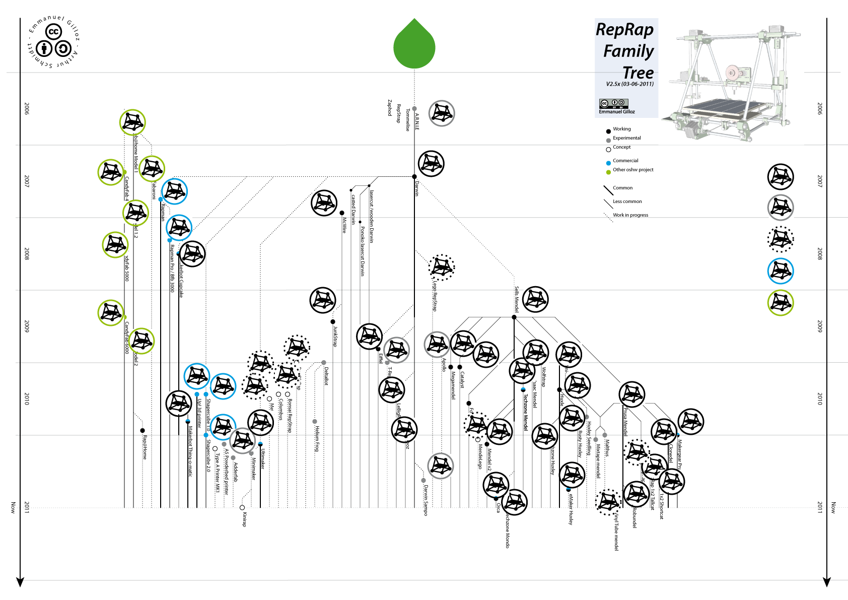
Rep Rap Family tree
Originally built by Andrian Bowyer. The Rep Rap was designed to be a machine that could self-replicate. In that it could print its own parts. Since then the open source community has developed many variations on the original design and continue to document and publish them.
Rep Rap Prusa-i3 ML3
Built from kits by Nicolo Gnocci for the Green Fab Lab, the Prusa-i3 are the most reliable 3D printers we have had. The component parts can be downloaded in OpenSCAD format and assembled and the machine costs less than 350 euros. Documentation and limitations of the Printer can be found on The Prusa Website Support page.
- Print Bed Area : 250 x 210 mm
- Print Height : 250 mm
- Nozzle width : 400nm
| PLA | ABS | NYLON | |
|---|---|---|---|
| PRINT TEMP ˚C | 180 < 230 | 210 < 250 | 220 < 260 |
| BED TEMP ˚C | Non | 50 < 100 | 50 < 100 |
| MOVE SPEED mm/s | 20 < 80 | ||
| EXTRUDE SPEED mm/s | 2.2 < 3.4 |
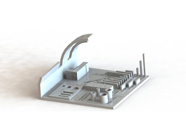
I had downloaded this all in one 3D test piece licenced by madja107 from Instructables as it seemed to be a good option to test the calibration of the Prusa-i3 MK3 in one go.
The Week 5 Class Pages provides test STLs that may be also be used to test the following design rules of the printer:
- Supported overhang
- Supported clearance
- Unsupported overhang
- Unsupported clearance
- Unsupported bridging
- Wall thickness
- Dimensions
- Anistropy
- Surface Finish
- Infill
In an ideal world we should also test each of these design rules for the multitude of filament types. For this week I will use PLA this week, it is a plant based plastic.
Using PRUSLICER
To generate the G-code needed to run the printer, we need to prepare the Calibration test STL file using a slicer. This is a CAM software that processes the STL geometry into readable g-code for the machine to follow. This type of software is called a Slicer as it essentially sections the model into slices that can then be built up in layers by the printer.
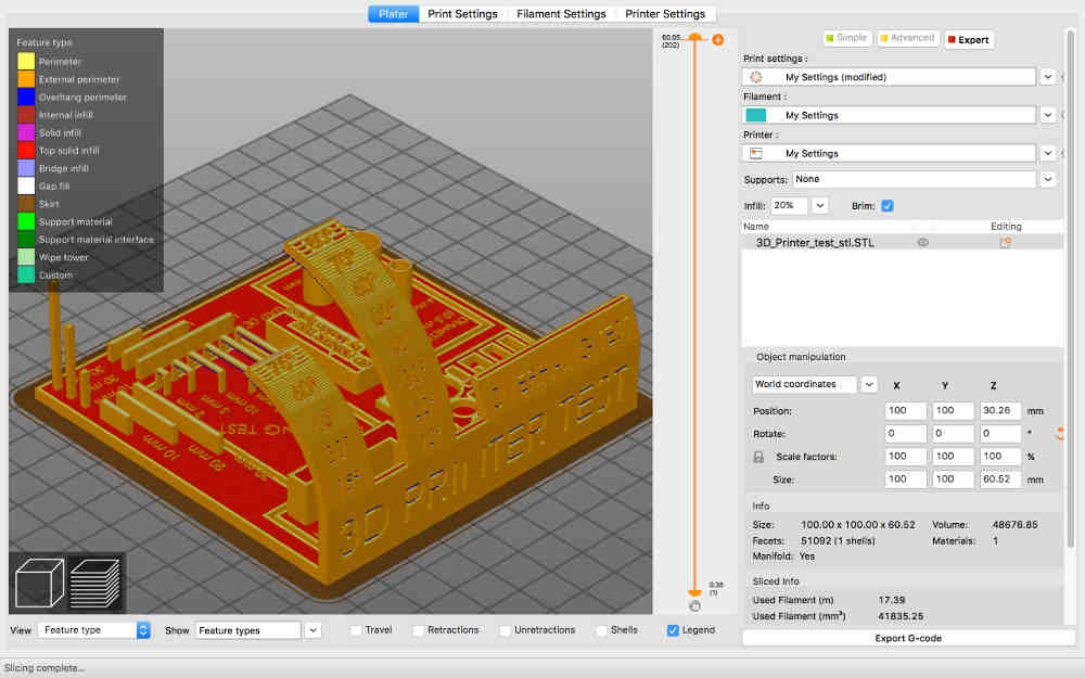
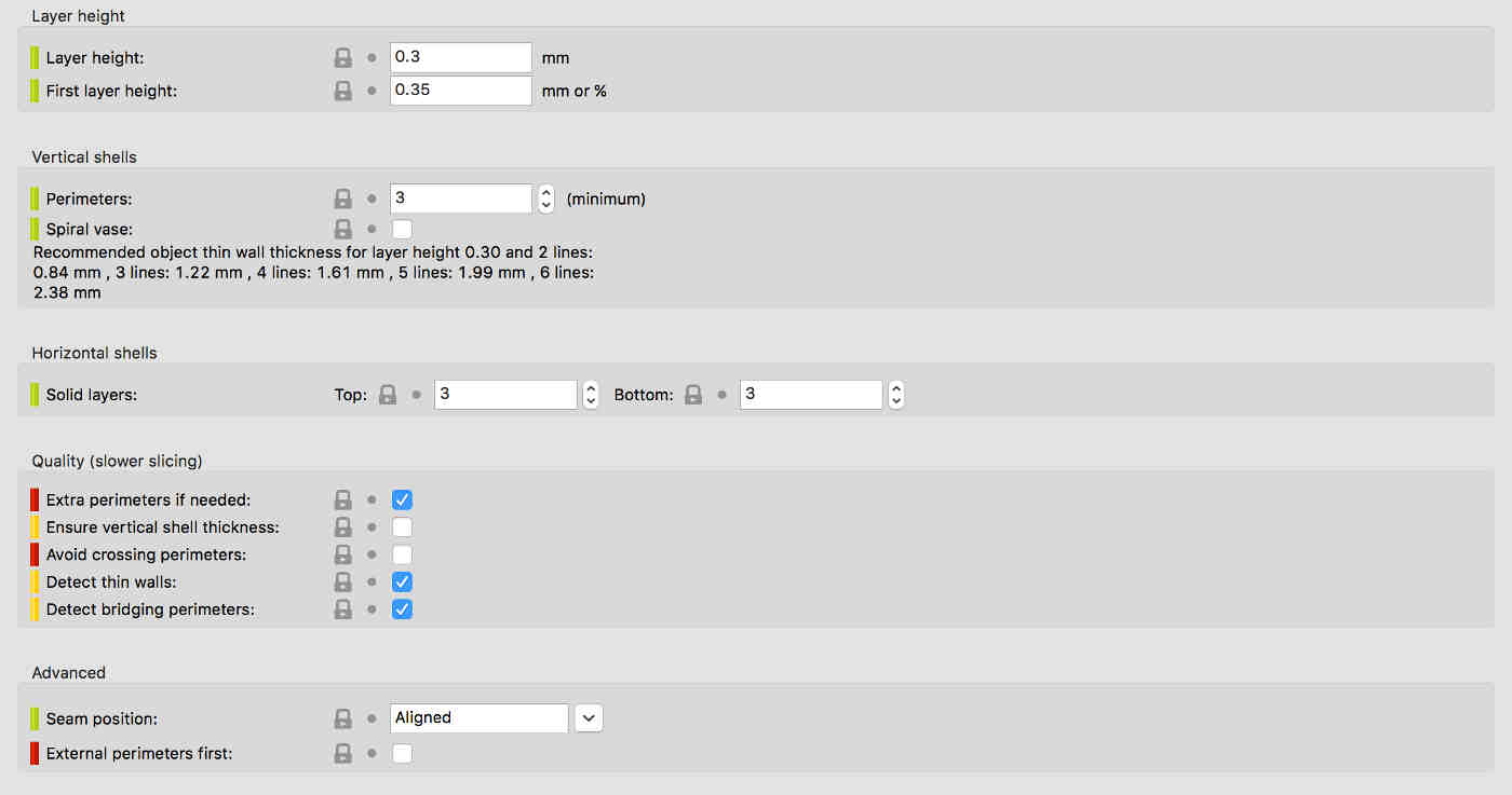
The advanced settings in Pruslicer can be set to control a wide range of CAM settings including:
- Addition of a base plate / brim or raft.
- Addition of support material.
- Control of feeds and speeds for particular filiments
- Control of temperatures
- Control of Solid and Gap infills
In addition to the main interface the download of pruslicer also includes some under the hood software called Pontiface. This allows for some extra configuration and coding options.
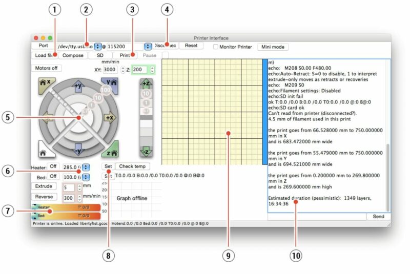
Figure 10 shows the dialogue box for reading code sent.
W5.2 : Print a Small Object
Gimbal Component
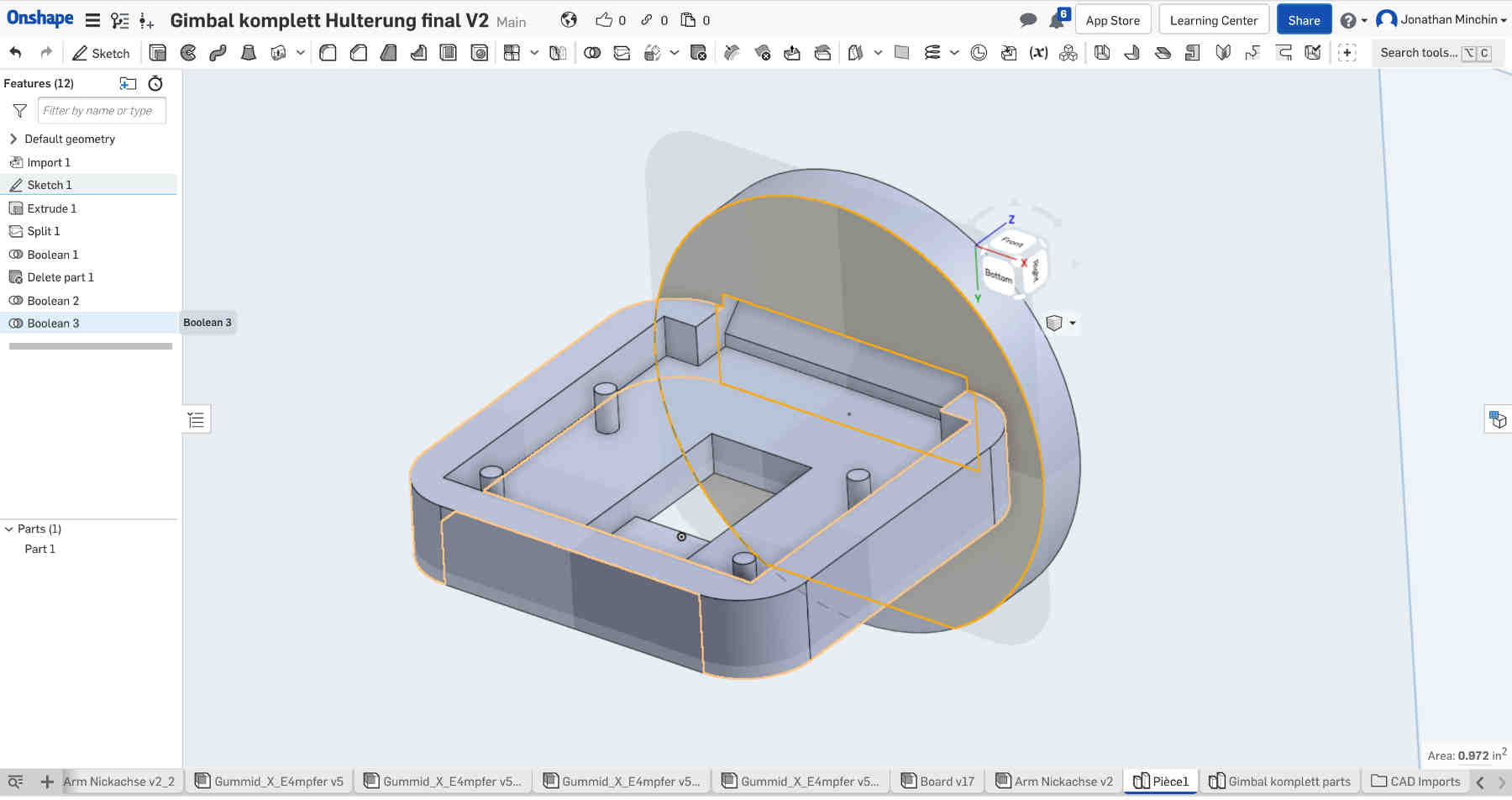
During Week two I had downloaded a PI CAM support by Yassin Klass from Grab Cad file now imported into Onshape. The next task was to merge the design into the ROMI gimbal and then print it.
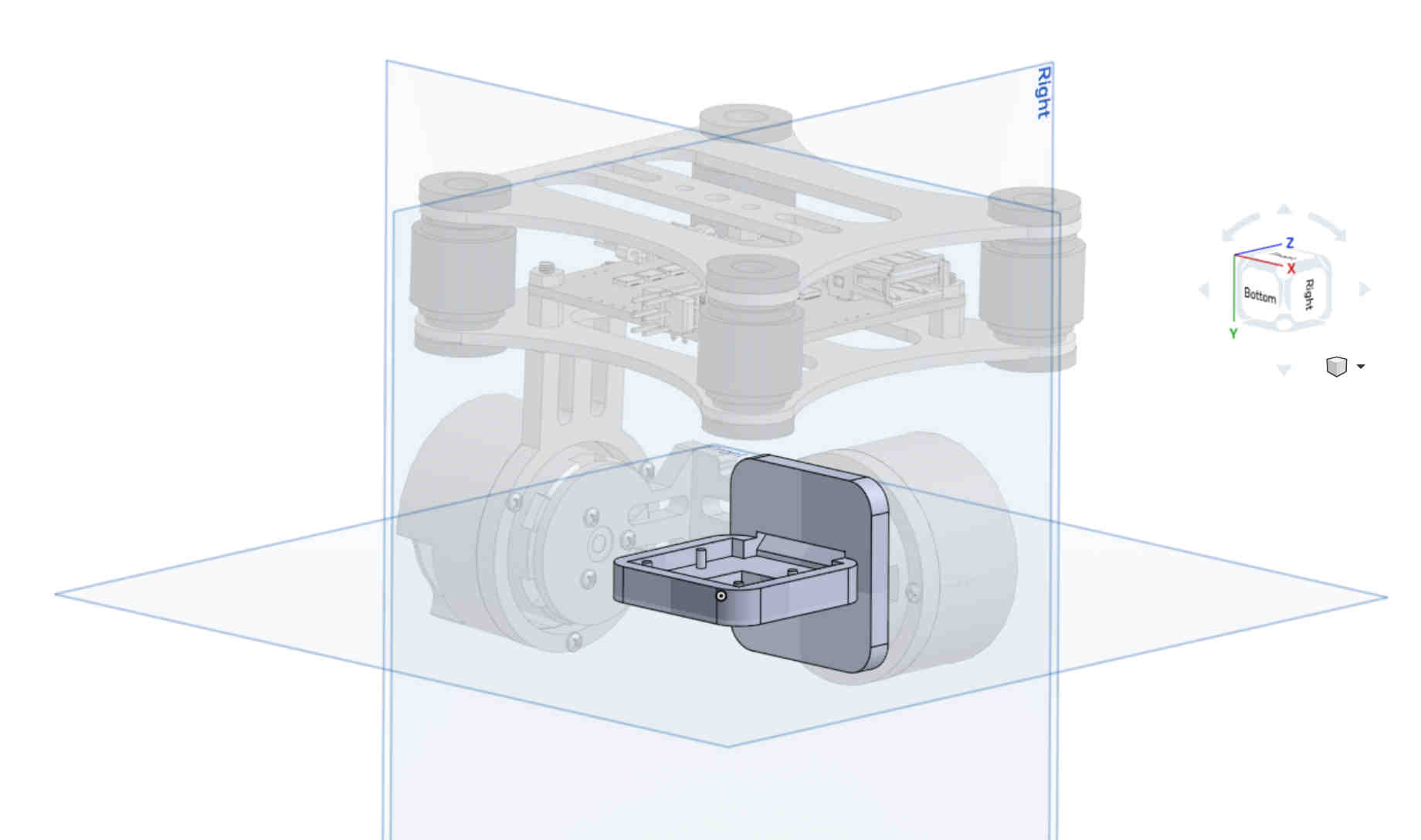
After mating the pi support to the central axis of the second motor i then made a sketch onto the component and removed the unwanted square edges with a boolean command. Finally I could download the part as an STL.
- To download the STL right click on the part tab at the bottom of the screen and select export.
I have uploaded the model to Sketchfab and embedded the model here at the bottom of the page.
Using OCTOPRINT
Octoprint is an open source Slicer software that allows users to run network their machines and run them remotely through the use of Rasberry Pi. This sits well with my academy objective of running machines through Single Board Computers (SBCs). My objective here is to print the Pi Support using an UDOO board with Linux installed.
The OctoPI Download and installation guide gives detailed instructions as to how to setup the system across various platforms and OS. and here is a video to explain how OctoPI can be installed and run on a Rasberry pi 3.
W5.3 : Scan in 3D
3D Scanning with a Drone
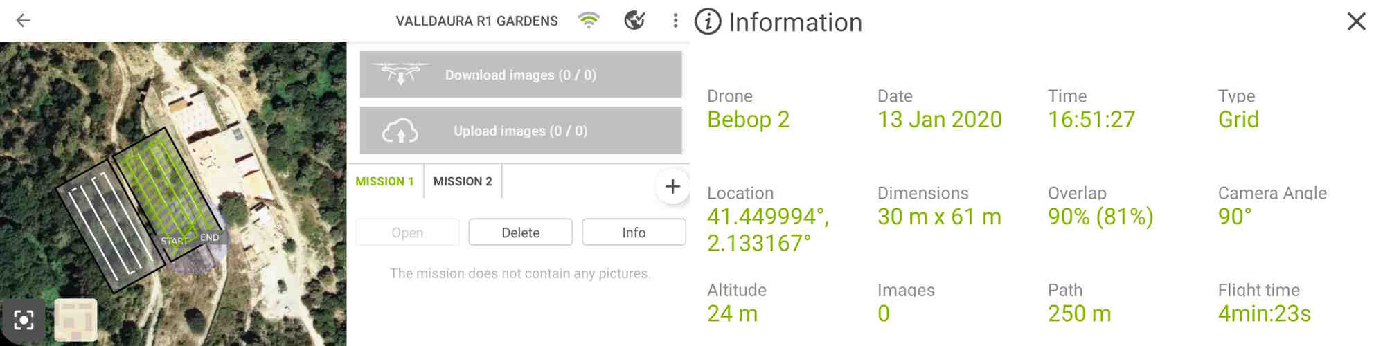
Free Flight Pro a is smartphone app used here in conjunction with Pix4Dcapture to design and program an automated flight path, in this case for a commercial Bebop2power Drone.
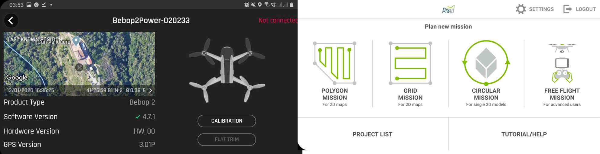
Pix4D can also be used to calibrate in a detailed way the camera angles, the location and height of the scan as well as organize path types and motion sequences.
Photogrametry using Metashape
Metashape by Agisoft and open source build for using photogrametry with point clouds. These means to calculate 3D points from 2D images by finding intersecting points between two images and stitching them together. By triangulating those images together with the position of the camera then a model of a scanned object can be made using those points.
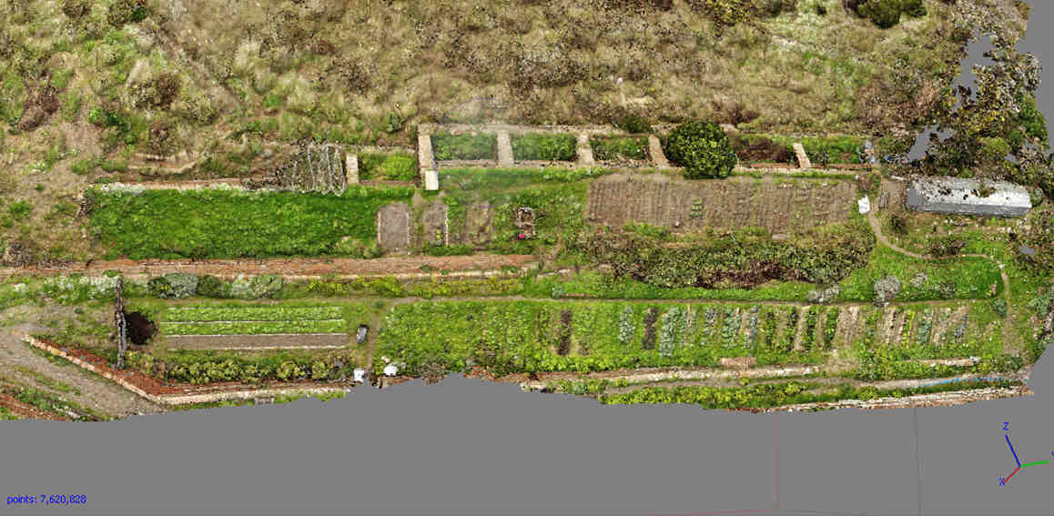 The RGB scan has 7620000 points.
The image above shows the results of the scan conducted at 50m height using the Bibop RGB camera. The image below shows the same land being scanned with a Mapir camera at the same height. The Mapir records a spectral range heigher to that of the RGB and can be analysed for NDVI : Normalised Data Vegitation Index.
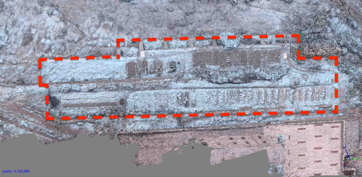 The NDVI analysis scan has 4760000 points.
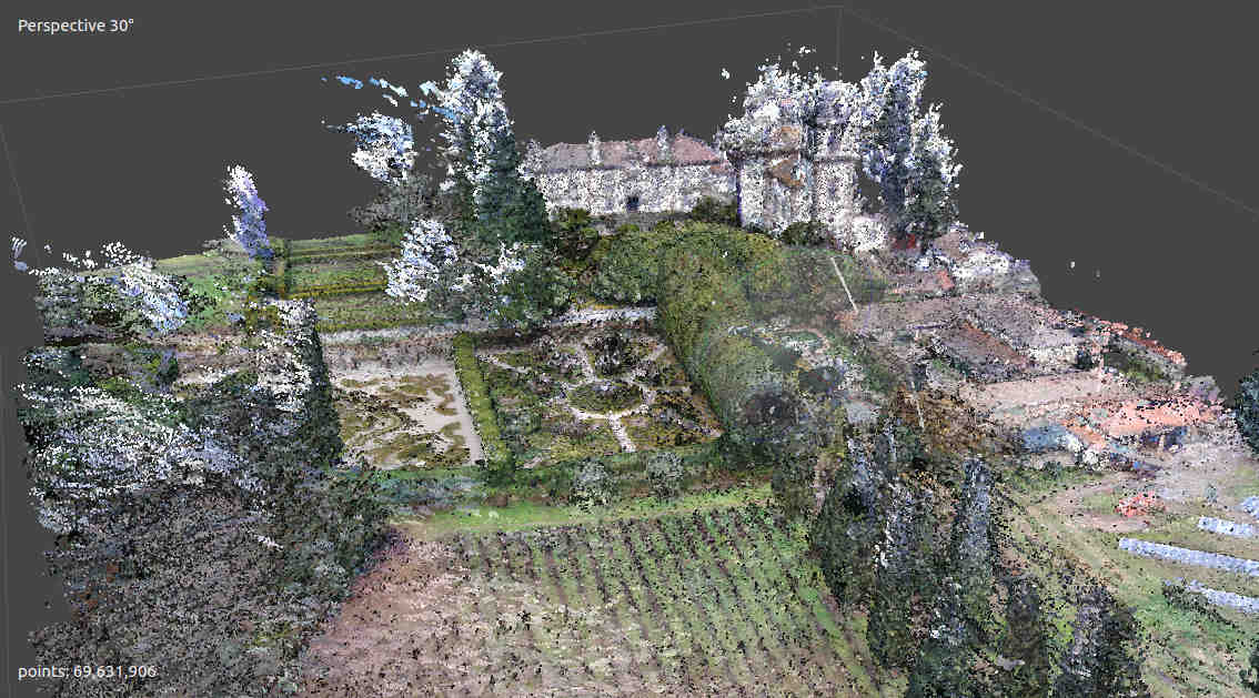
Here is a point cloud of a Scan over the Casa de Mateus Gardens in Porto, Portugal. (Soon to be another Green Fab Lab)
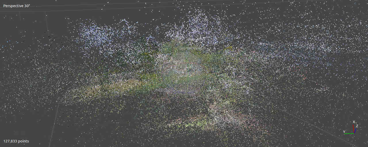
The image took over a day to generate and has 127,833 points.
I had discovered that the fish eye lense of the camera was not accounted for in the settings and so adjusted the settings to account for that.
- Stitch Images
- Build Point Cloud
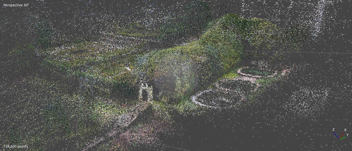
The image took over a day to generate and has 158,600 points.
After sucessfully mapping the images into a Dense point cloud I was finally able to toggling between views that show the points and a photo mapping of those points.
- Build Dense Pointcloud.
- Toggle to photo view.
Computational Tools with Potree
Potree Image of Valldaura Gardens and a link to the online version of the image from the ROMI documentation page :
Valldaura Gardens NDVI scan in Potree
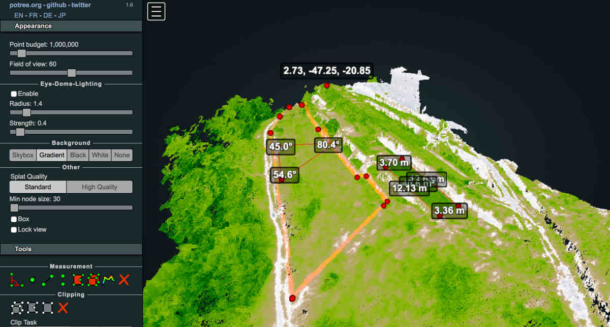
The image took over a day to generate and has 69,631,906 points.
3D Reconstruction of Plants with ROMI Phenotyping Scanner
Visualizing of Plant Data with ROMI web apps
3D Reconstruction of Plants with Skannect.
Digitizing leaf data with the MDX 20
Useful links
Class Questions :
- Placing of the Div class in the page breaks all subsequent text and links.
3D Models
- I had uploaded the STL to Sketchfab and then used the embedd code they provide to link the image to this site. I have had problems with code not workign after the iframe however.
<div class="sketchfab-embed-wrapper">
    <iframe title="A 3D model" width="640" height="480" src="https://sketchfab.com/models/a4bd676b4eaf423b9972230af43f9d9e/embed" frameborder="0" allow="autoplay; fullscreen; vr" mozallowfullscreen="true" webkitallowfullscreen="true"></iframe>