3. Computer Cutting
Processes of cutting in two dimensions. Primarily using a vinyl cutter and also a laser. Precision tools. Stencils, stickers, circuit boards with the Knife of a laser. The Laser being one of the most used tools in a Fab Lab with the Vinyl being one of the least.
Kerf, laser has a spot size (to 0.01 / inch) and the Knife of the Vinyl has a edge thickness. (to be within 0.5 / inch)
LASER is an Acronym :
“Light Amplification by Stimulated Emission of Radiation”
WK 3.1 : Characterize Vinyl cutter settings and make a test cut patch
WK 3.2 : Design for cutting 2D
WK 3.3 : Cut a sticker using Mods with Vinyl Cutter
WK 3.4 : Characterize Laser cutter settings and make a test cut file
WK 3.5 : Designing 2d for 3d assembly
WK 3.6 : Cut a construction kit using a Perez Camps laser cutter
WK 3.7 : Design and Cut a 2d for 3d Textile pattern
WK 3.1 : Characterize Vinyl cutter settings.
Type : Roland CAMM-1 Vinyl Cutter
Model : GX
Language : HPGL
Note : 22”
Material : Vinyl
Depth :
Force :
Speed :
WK 3.2 : Design for cutting 2D
Use Inkscape edge trace directly to the vinyl cutter.
For this task I will use a Roland CAMM-1 Vinyl cutter directly from Inkscapes’ post processor option. Here i am taking direction from this useful Inkscape Image preparation Tutorial.
I had chosen to use different types of ROMI logo for this task as there designed to demonstrate a ‘tool path’ as part of their concept. (The rover moves along set CNC routes).

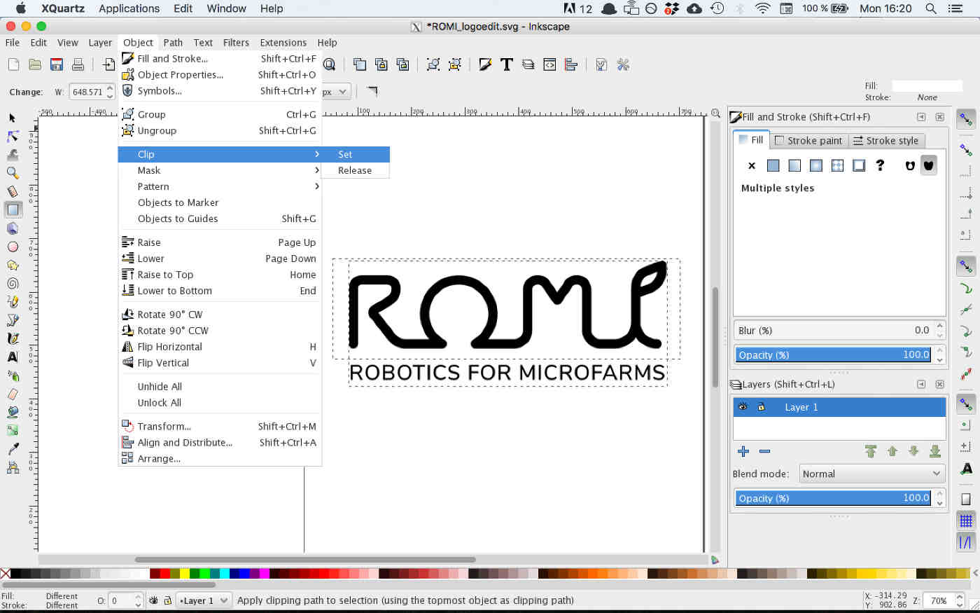
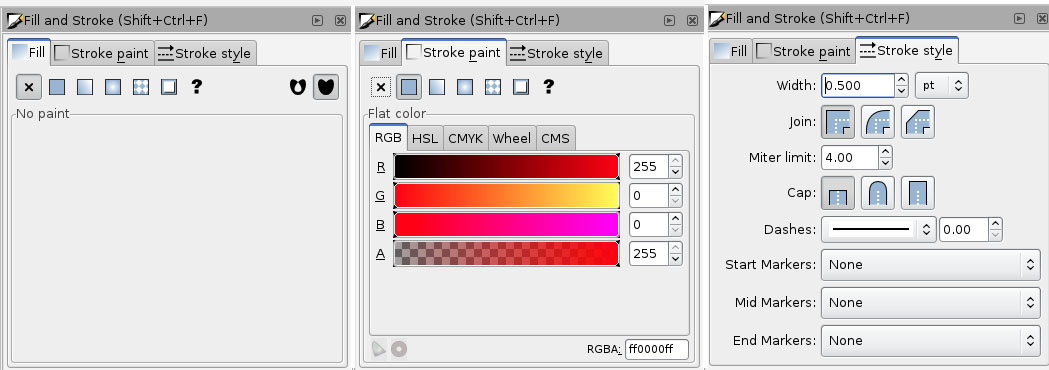
The first job was to import the image file into Inkscape and then remove some of the unwanted text by using the clipping command. The F4 key can be used to open the fill and stroke selection tool. This must be set to become a clipping path by first removing any fill settings and zeroing the (RGBA) settings. This video by Technical Writing explains the steps clearly.
I now needed to use Inkscapes Trace Bitmap Tool or Edge Tool to select only the vector around the perimeter of the ROMI logo object. This video by TJ Free describes in detail the steps of working with the tool. Whilst having the image selected go to path > trace Bitmap. I set the edge detection to be at 0.7 points to achieve an accurate trace.
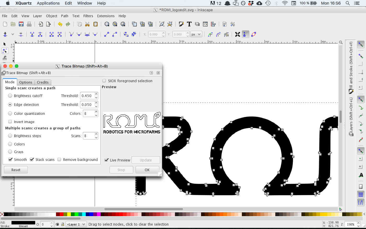
To generate an outline vector I toggled the live preview and update, options until I achieved a sufficient vector point mapping, noting that the points are generated as bezier curves. To view the curves I toggled the edit paths by nodes tool, this can be achieved by with the (f2) key also.
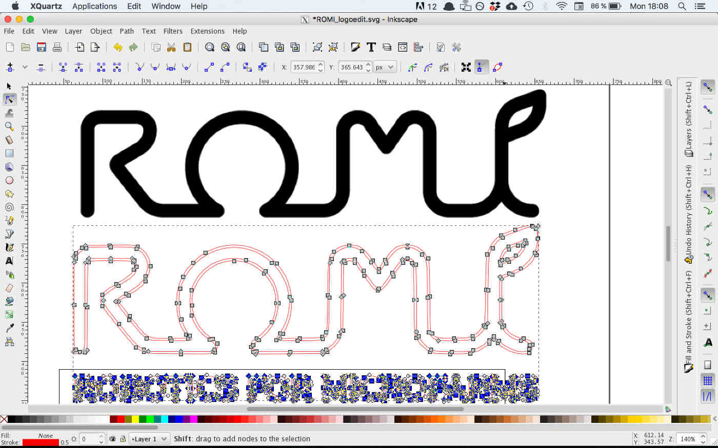
I questioned why the text below my image had been detected by the Trace Bitmap tool after I had tried to clip it. Yet I was able to now delete unwanted vectors and points using the edit paths by nodes tool.
In theory Inkscape should have the post processor for the Vinyl cutter as an option to print. This means that it is running its own to run the vinyl cutter directly. Vinyl Cutter / Inkscape Tutorial and here is an image of the cutter I am using taken from that tutorial page.
To interface with the Roland CAMM-1 some job dimensions needed to be setup also. The proportions of the cutting area needed to be set to coincide with those of the physical limitations of the machine. (Shift+Ctrl+D) will open Document Properties dialogue box.
- Set the default units to (in) inches.
- Set the default units to (px) pixels
- Set the document width the vinyl width (22” or 13”).
The Roland CAMM-1 is set at 22”
- Warning : the document height is must be larger than the document width.

At this point I was could delete the original image object or move it to a safe hidden layer. Finally the drawing vector path would be ready for sending to the machine. It seemed that the print processor driver I needed was not installed in this version of Inkscape.
- Some Cut Studio driversare available, although mostly for windows.
- This Inkscape Forum offers some advice for alternative setups.
- An application called inkcut is multiplatform and open source, also working with Rasberry Pi. I have tested it below.
I could not find the drivers for Inkscape that i needed and so decided to try InkCut instead. This link describes the process of the device Setup and below is a gif of the details. I have included this because I think it could be a valuable addition to the Academy software set.

I was able to load the .svg file created through Inkscape directly into Inkcut. It appeared in the viewer with tool paths set already.
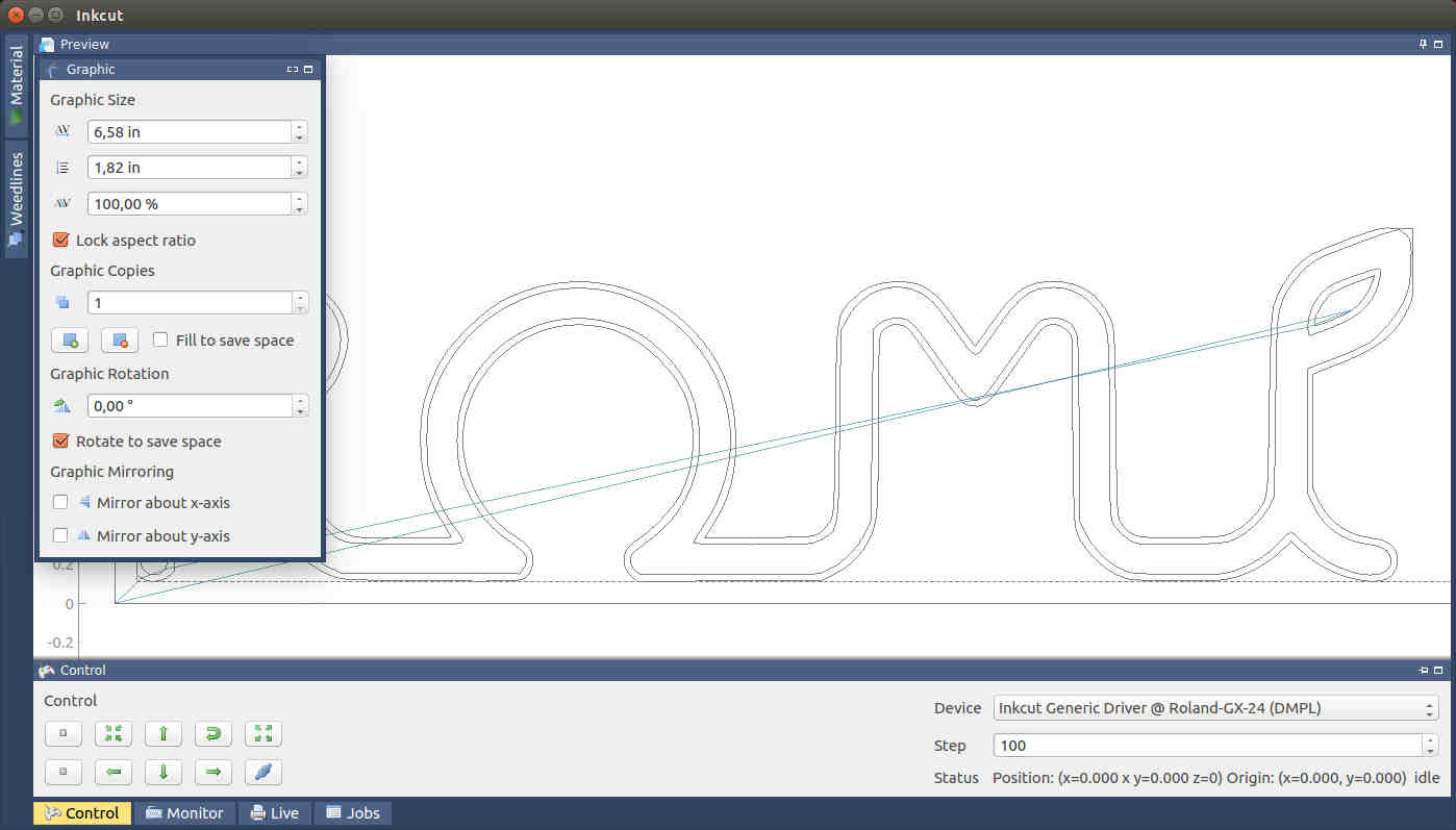
FILE LINK : 01_romi_ink_edge.svg
WK 3.3 : Edge Detection using Mods with Vinyl Cutter
Use Mods to detect edges and export a PNG vector.
I was excited to use MODS to create an edge detection that can be used to generate a toolpath and then send that directly to the Vinyl cutter. This will be an important process later in the Academy to cut circuit boards.
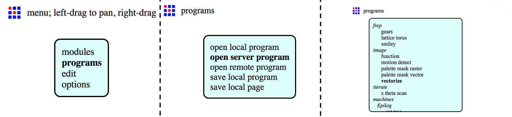
To use MODS :
- use right click anywhere in the site to activate the menu.
- Click server programs for framework options.
- In this case I loaded the ‘Vectorize’ option.
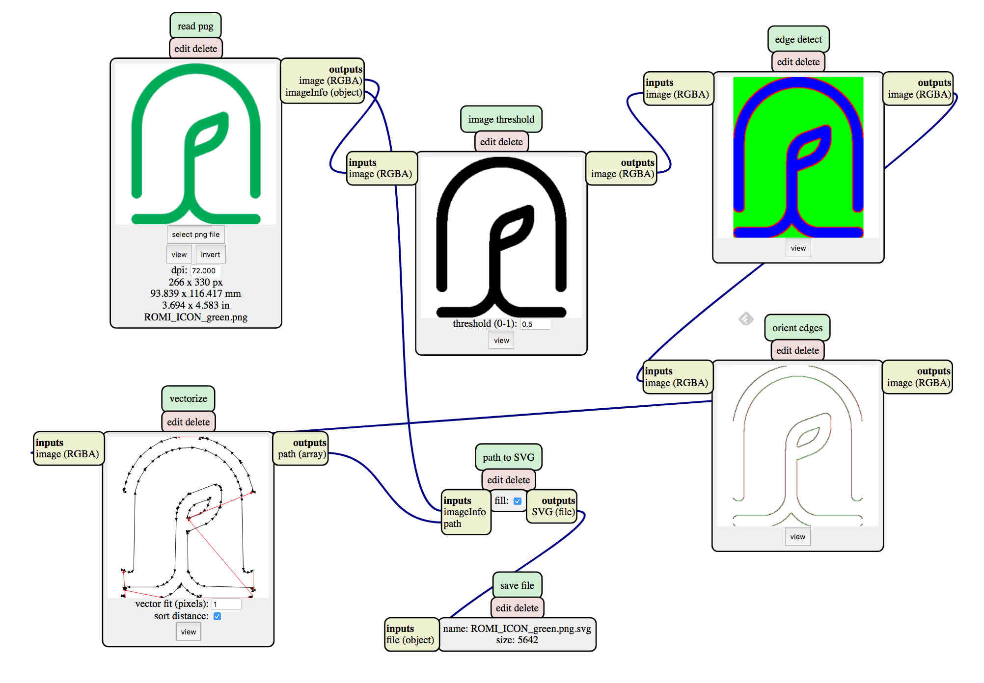
Use Mods to export a PNG for the vinyl cutter.
WK 3.4 : Characterize Laser cutter settings and make a test cut file
Type : Perez Camps
Model : PC 16/10 2 (C02 Laser)
Note :
Software : Smartcarve 4.3
Material : 6.5 mm Abadul ply wood.
Speed : 13
power : 90
Frequency : (not applicable on C02 laser)
Lens : to Material distance : 9mm
WK 3.5 : Designing 2d for 3d assembly
The first of this weeks task was to build a structure to be designed to be machined by the laser cutter and for cardboard construction. The structure would use CAD software and should be assembled using digital joints.
- Push fit
- Champfer
- Flecture
- Snap fit
- Pinned
- Finger
- Wedge
Shapes were to have male and female connectors and fittings ready to be assembled directly from the machine and with no bridging connectors. A design method such as this could be used to create a set of adaptable, interlocking pieces, much like lego.
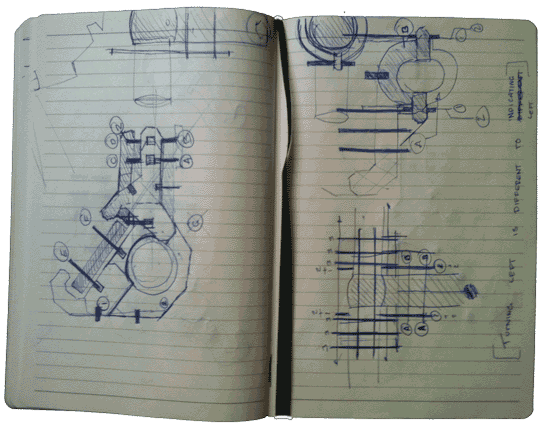
Sketch Testing and Ideas
I designed phone cradle to be mounted on the handle bars of a racing bike and will carry an old i-phone 3. The design would also have to encompass a fit and release mechanism so that it could be removed from the handlebars, or the phone removed from the cradle.
Connecting objects.
I first sketched the idea out using pen and paper then used adobe illustrator to measure out my drawings more accurately. Illustrator allowed me to easily change dimensions and to create quick and effective changes to the design.
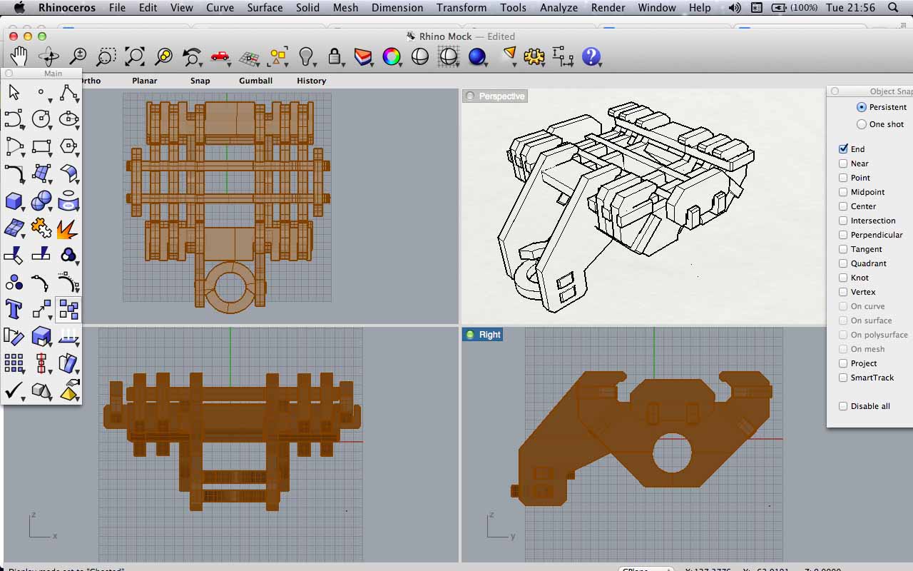
Quick Press-fit lattice model in Rhino
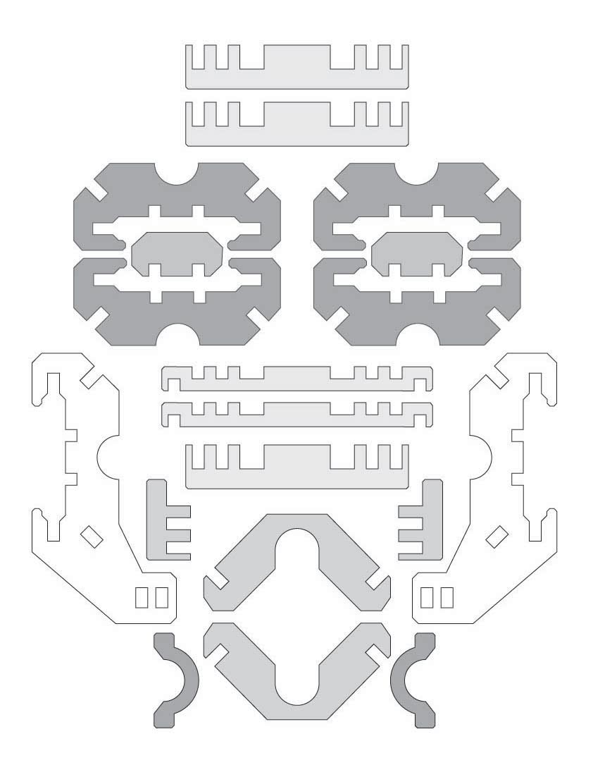
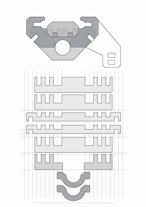
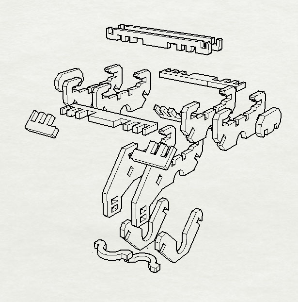
I exported the drawings using the .dxf file type and then used Rhino to 3D model the drawing in such a way that I could see how well it aligned and fit together. Creating the project in virtual space before construction and printing will have saved me paper resources, time on the machine and redesign effort also.
I used the laser cutter with 6.5 mm thick ply wood. At the time of printing this was different to the size that I had prescribed in my design, which was used a 6mm depth for each slot.
The ply of 6.5mm thickness would work most efficiently when tightly packed; this meant creating as many structural components from one piece of A3 card as possible. Less wasted space from the card would also prove to be a plus point.
The Constraint solver using Free Cad
Use FreeCAD to make a parametric Version Bike phone Cradle I understand this has the capacity to accurately measure forces, pressures and environmental conditions for structures.
WK 3.6 : Cut a construction kit using the laser cutter
The CAM software used was Smartcarve4.3 (manual linked here). Files can be uploaded as .AI files or .dxf. I had understood that the .dxf type is being fazed out, yet it seemed to me after multiple attempts at changing settings, the dxf was the only one that the program accepted.
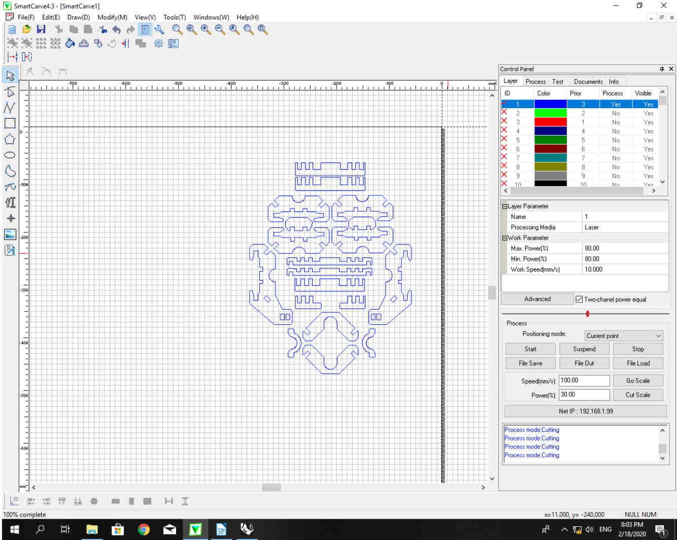
The Smart Carve software is very easy to use. Simply moving and positioning your drawing and assigning components to colour layers is all that is really needed. By toggling the process settings and then sending renaming the job I could start testing for:
- speed
- power
- kerf
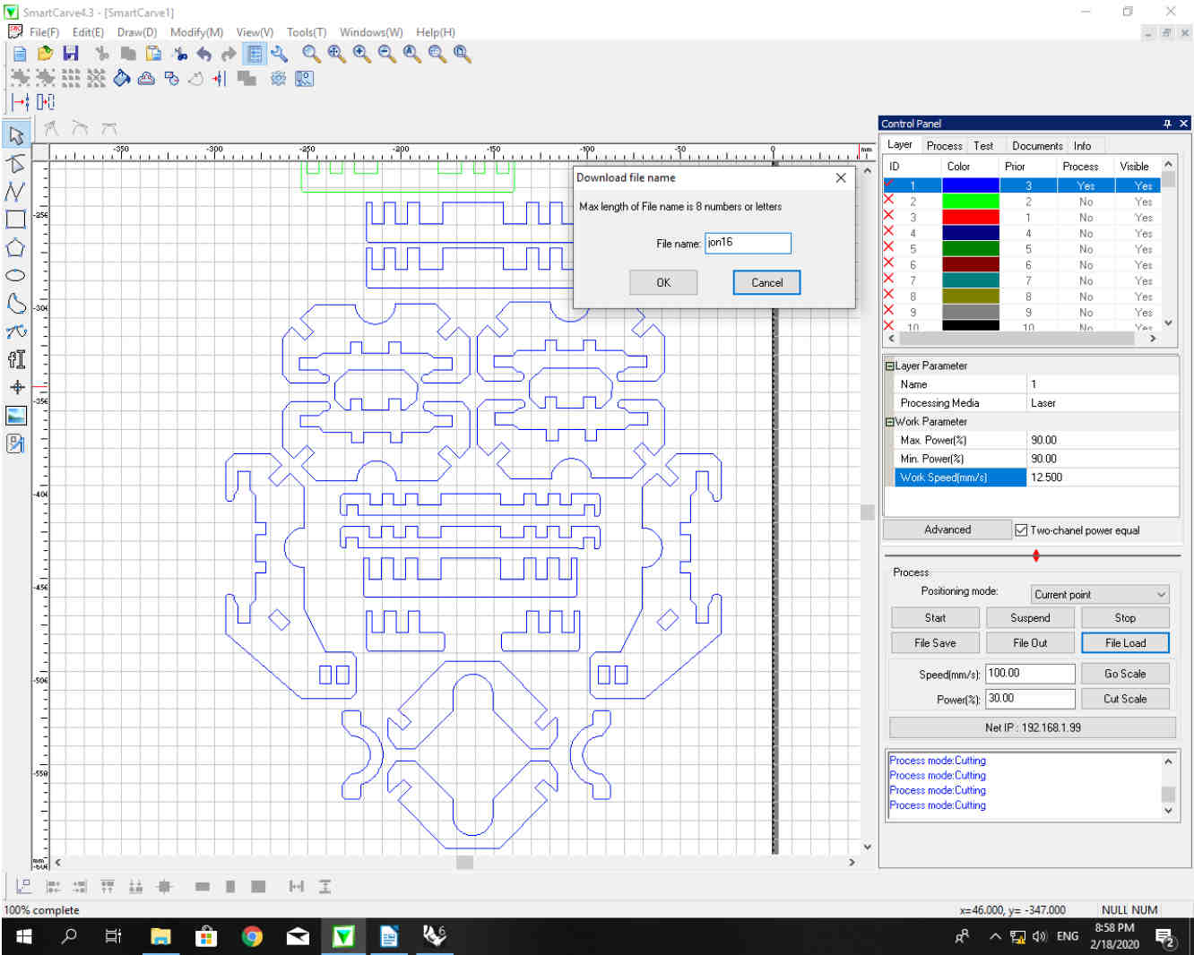
Having hit File Load and sent the tool path to the laser it was then possible to check that the file had been loaded correctly and that the settings were accurate.
The task now was to characterize and calibrate the laser settings to the chosen material. After 15 test cuts I was able to determine that the most successful combination of speed and power would be found with a combination of :
TIP - “Higher power + As fast as possible”
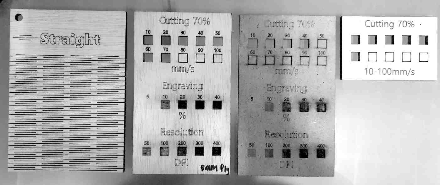
Having increased the power incrementally the best result was found between Speed 10 and 15. At the lower end (10) there was a likelihood for the material to burn, and closer to (15) the laser would not cut all of the way through the material.
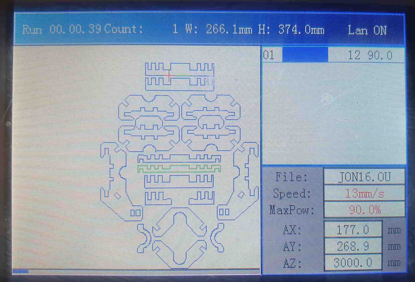
Running the Perez Camps machine was very simple. After loading the material into the top right of the machine bed it was possible to Zero the (X,Y) coordinates by pressing Origin.
The (z) axis or the distance from the laser lens to the material was setup manually with a sliding rule to the distance of 9mm.
Loading and running the file was simple, there is also a viewer that allows you to watch the movement of the machine along the vector toolpath.
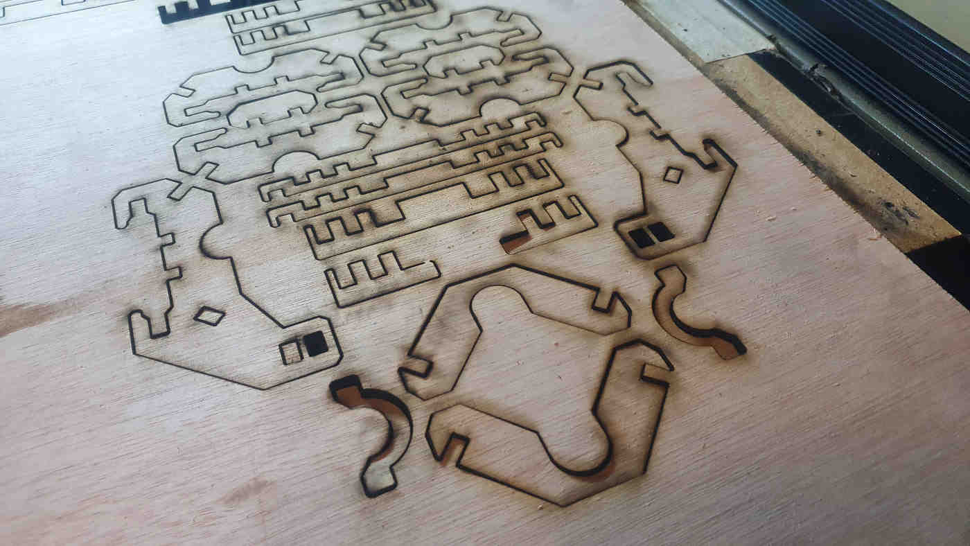
The file above shows the results of the the cuts laid out on the machine bed. some of the components had dropped out fallen through to the container at the base, it is also possible to see the scorch marks where the material ignited. If you look really closely, the Nesting layout resembles the face of a baboon!
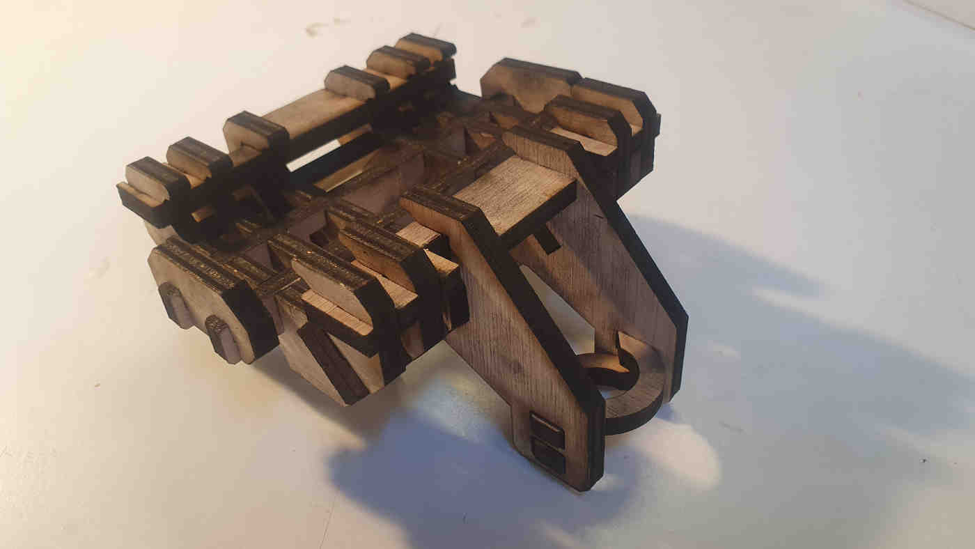
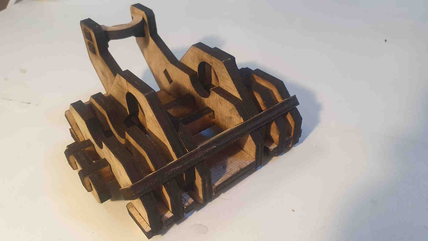
The Kit is pressed together very tightly, I am pleased with the rigidity of the assembled cradle. only at the point of final assembly did i realize some mechanical failings of the prototype. The next version would assemble all horizontal lattice pieces from the inside of the cradle. In this way it they would be locked in by the phone in place. The side pieces would also be improved by using a Snap fit.
WK 3.7 :Design and Laser Cut a 2D to 3D textile pattern
- ‘unroll ruled surfaces’
- Seamly
- Fabricademy : OS Circular Fashion
Useful links
- Academy Class Page : Computer Controlled Cutting
- Class Video : Computer Controlled Cutting
- Academy assessment Guide : Computer Controlled Cutting
- Mods
- Seamly
- Fabricademy : OS Circular Fashion
Class questions
- (Inkscape) Why does image detection find objects after a clip?
- (Inkscape) Why are there two vectors generated from the trace outline?
- (Inkscape) There is no print driver for Roland Camm-1
- (Git) How best to create an issue about the missing driver.
- (Git) How best to suggest that inkcut could be used.
- (Samples) Download Cut Samples.