8. Electronics Design: Board for Final Project
GROUP ASSIGNMENT
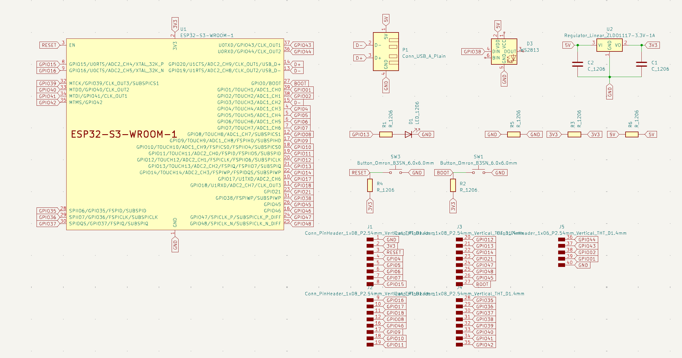
This page will be the documentation of the design of the controller for my final project. I am using an ESP32-S3-Wroom-1 to allow for networking across WiFi. It will also serve as the base for the overall electornics that will later be created for the input and outputs.
To design this board I worked off of a board designed by Josep Marti. I used his initial placements and adjusted it to my needs.
Copmonents:
- ESP32-S3-Wroom-1
- Reset Button
- LED
- Boot Button
- USB
- As many exposed pins as possible (to create a shield later and give me flexibility in the inputs and outputs)
KiCad
KiCad is a free software suite for electronics design automation (EDA). It facilitates the design and simulation of electroinc hardware for PCB manufacturing.
In KiCad, create a new project (.pro) where you will be able to design your schematic and your PCB.

Once you have connected all the traces and are happy with the shape of your board you can then export it as shown below.
Schematic
PCB Design
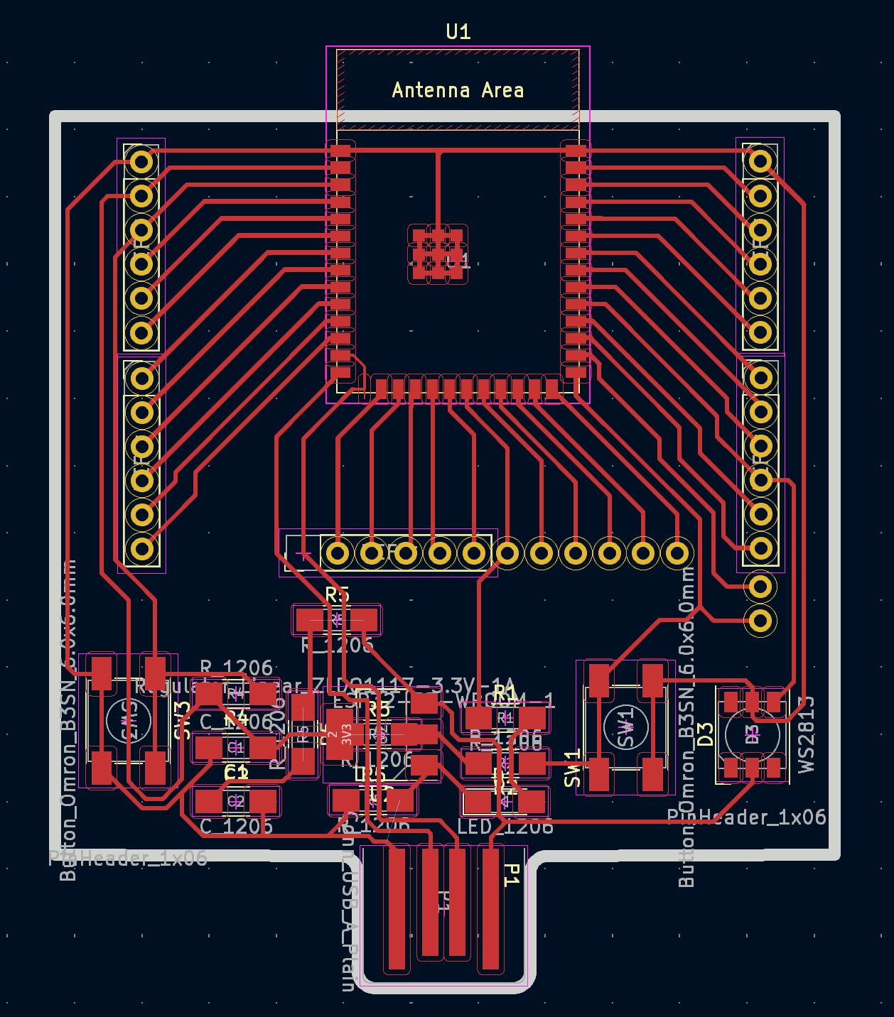
I used multiple 0Ohm resistors as jumpers to be able to expose all the pins I wanted.
Below are the netclasses rules I used:

Exporting

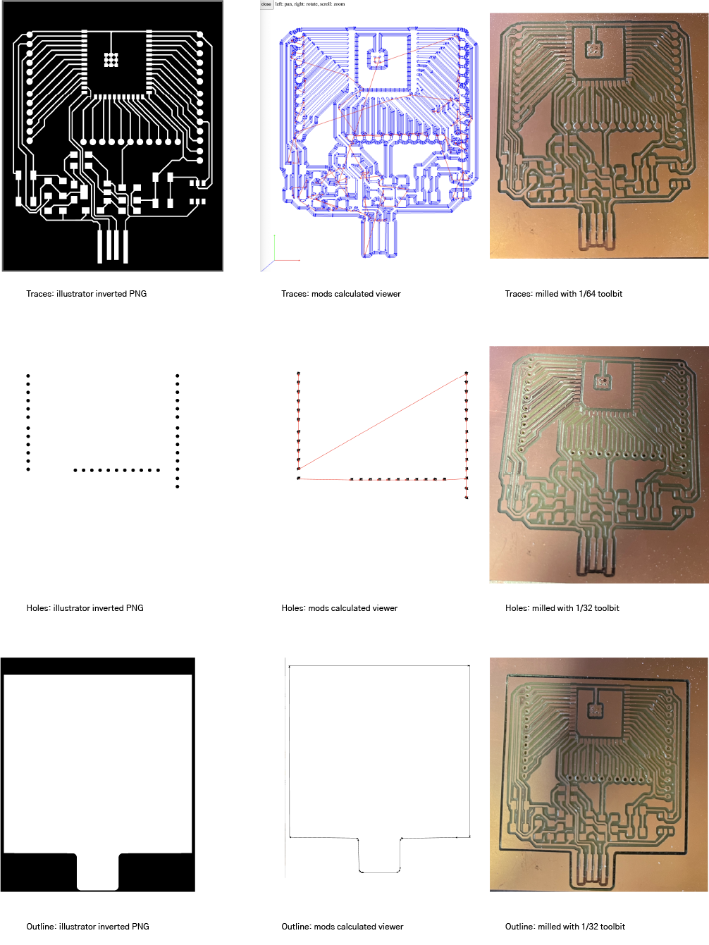
SVG Preparation for Milling
To export the board as an SVG to be placed in Mods for file preparation, I exported three files, traces, holes, and outline. The traces include everything, the holes are the pin connectors, and the outline is the outer cut.
In Illustrator, I inverted the SVGs so that everything black = cut and white = keep
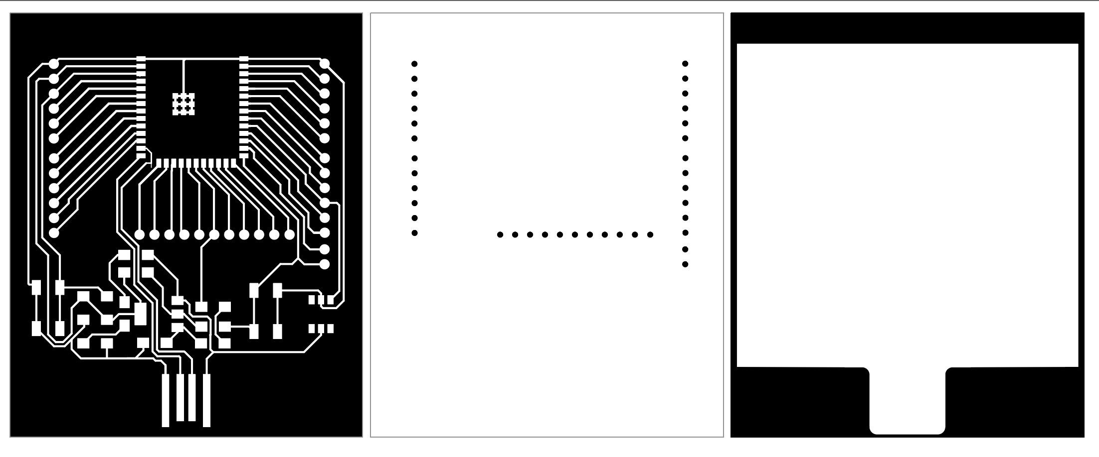
Export them as PNGs all the same size. My size is 60 x 73 mm. I grabbed a new PCB that is 101 x 152 mm, taped the back with double sided tape and placed it on the bed of the Roland SRM20. Make sure to sweep it up first because any minor differences in the level would be obvious when cutting the traces.
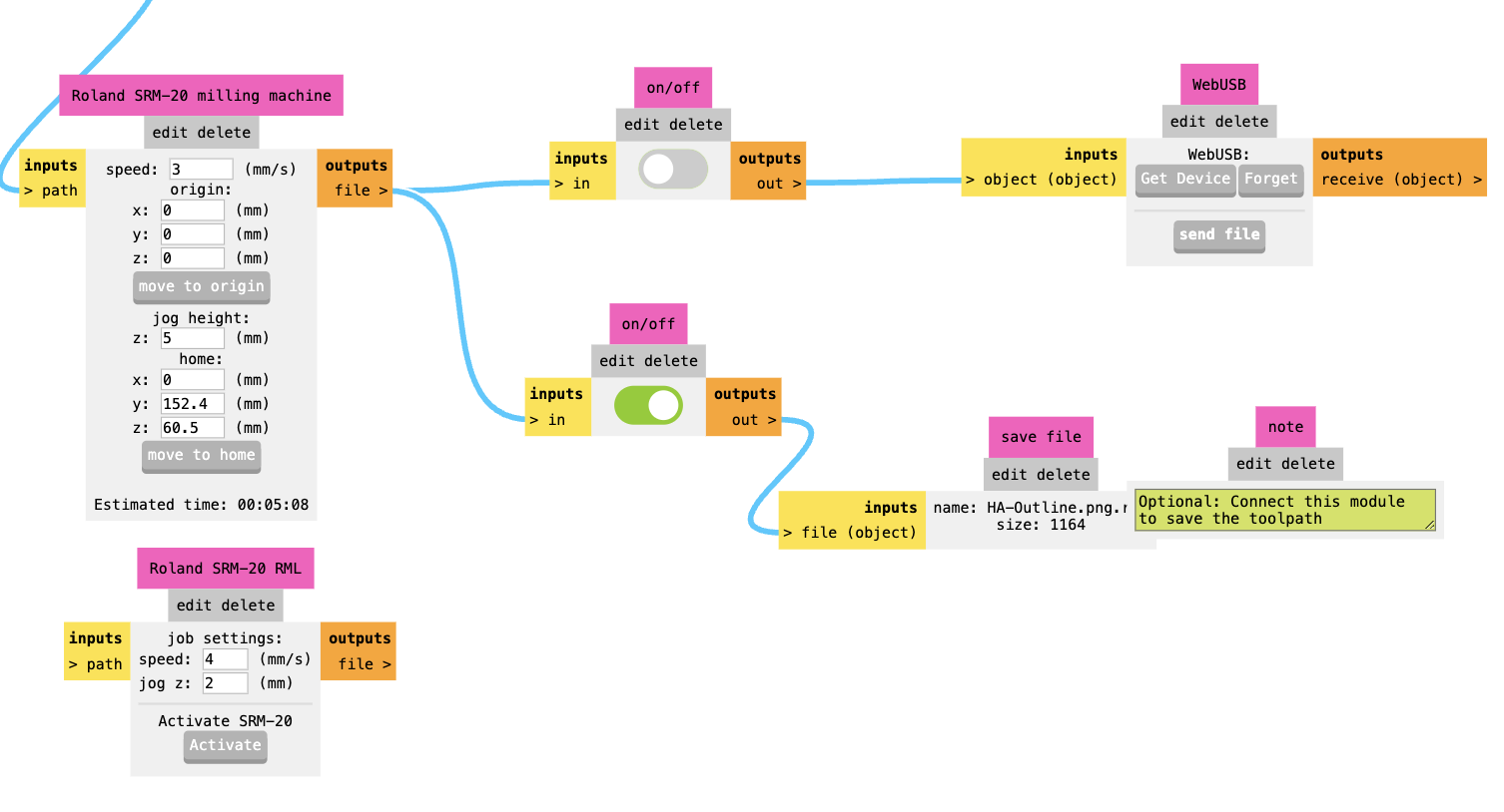
Mods
Using Mods I prepped my file to mill. I initially put in the inverted SVGs but realized it was not always seeing the files properly and so then used the PNG.
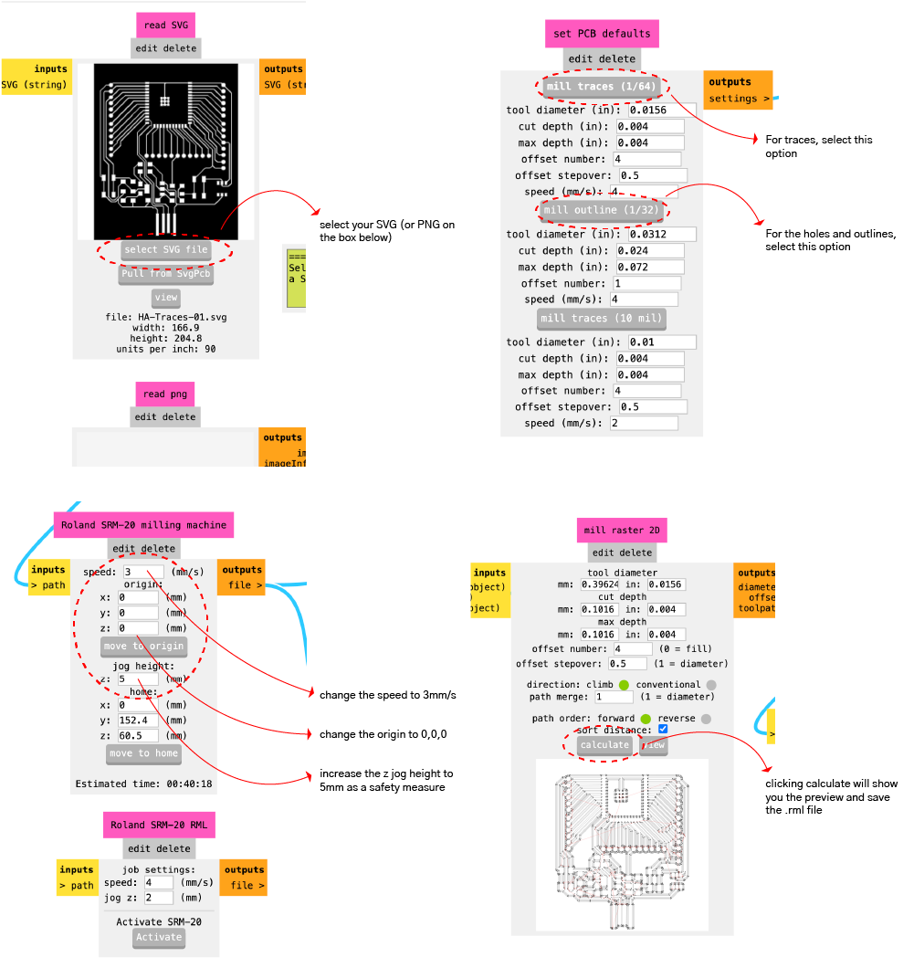
If the .rml file does not save directly make sure that the bottom module is turned on. shown below
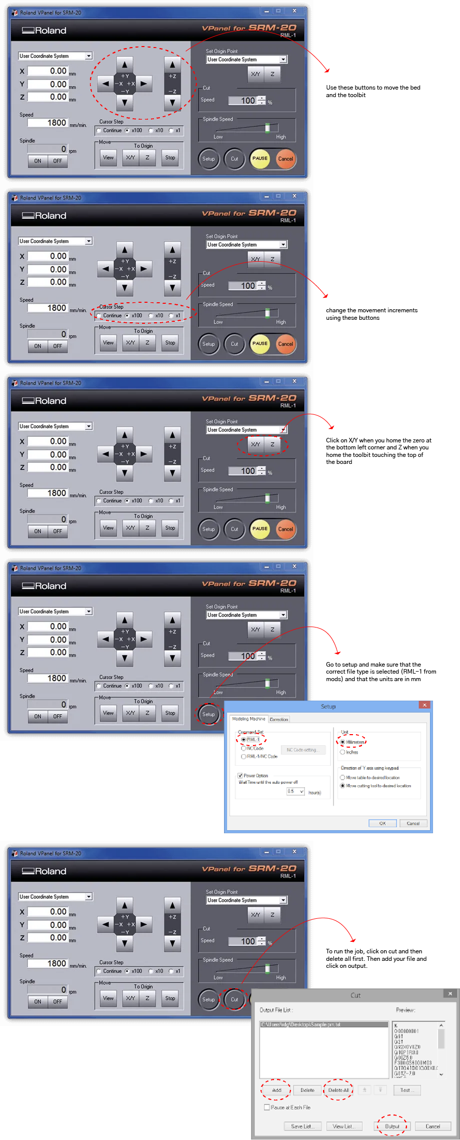
Milling
Using the Roland's software I homed the xyz zero and then ran the files one by one. Make sure that in the setup you select the correct type of file .rml or automatic and that the units are in mm.
When zeroing the z axis, make sure to move in small increments so that you do not crash the toolbit and break it. For the smallest precision, you can lower the toolbit by hand to rest on the board.
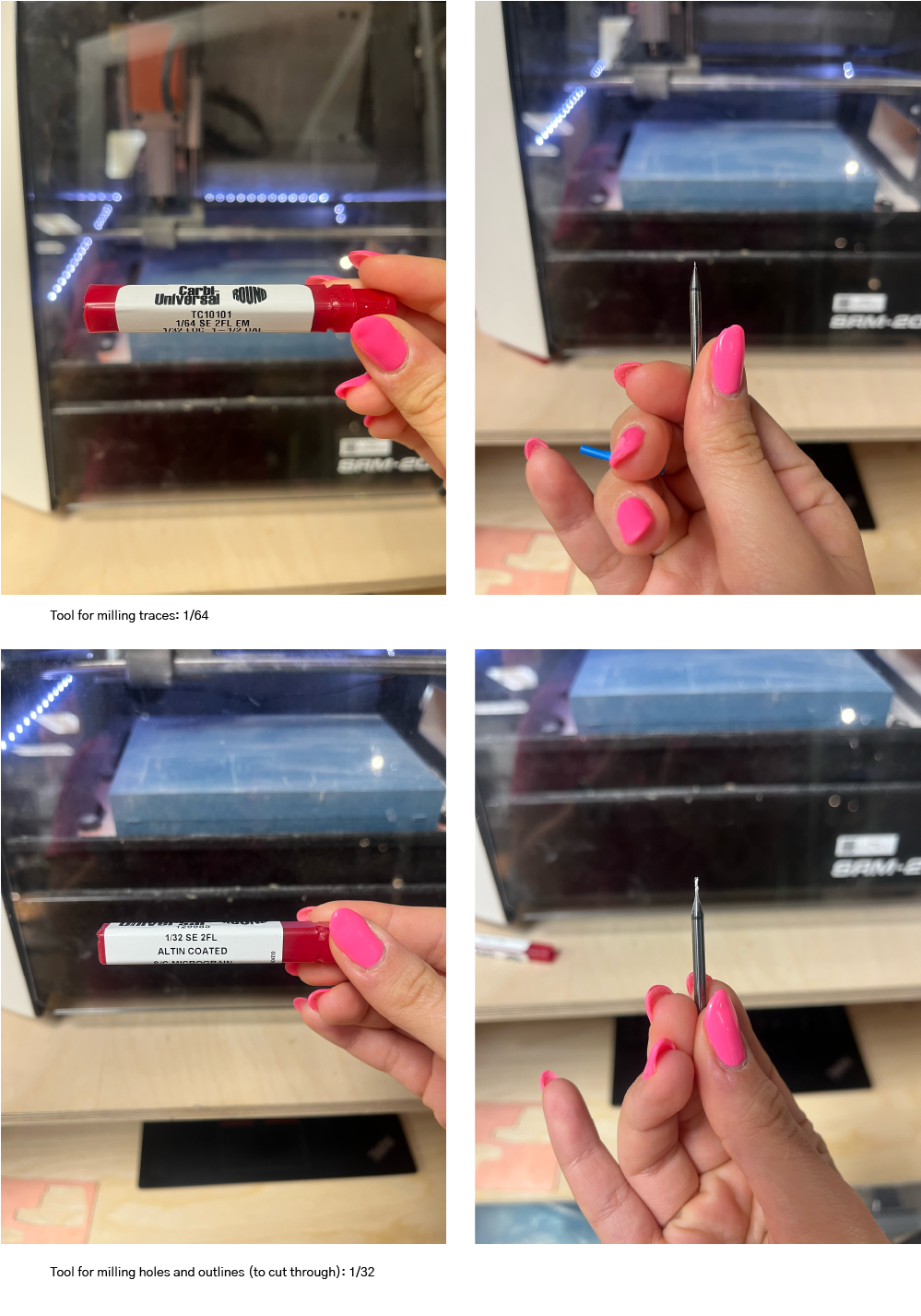
EndMills Used
Also, do your best to tape the baord down as flat as possible so it doesn't curve up in the center.
Soldering
Components:
- ESP32-S3-WROOM-1
- USB Connector
- R1 1206 (10Kohm - 1002)
- R2 1206 (10Kohm - 1002)
- R3 1206 (560ohm - 561)
- Switch 1
- Switch 2
- Neopixel WS2813
- Regulator (3.3V 1A)
- LED 1206
- C1 1206 (10uF)
- C2 1206 (10uF)
- Header Connectors
- Jumper R0ohm (GND)
- Jumper R0ohm (3V3)
- Jumper R0ohm (5V)
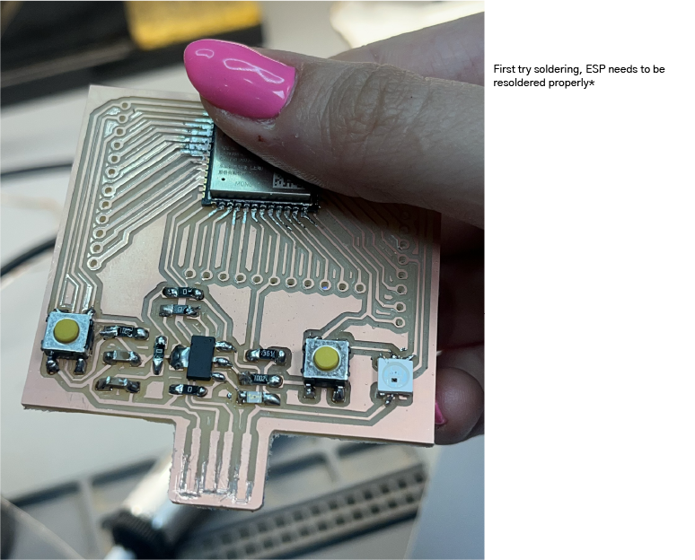
Continuity
Before plugging it in, I checked continuity to make sure that everything is soldered correctly. I realized that there was a missing trace so I re-milled the whole board then re-soldered it better.
Checking the continuity, I realized that the 5V and 3V3 were touching because I was using too much solder. After fixing that, all the connections were as they should be!
Test Code
I plugged in the board, pressed on Boot and Reset and opened Arduino IDE.
Blinking Test
I started with a blink test which worked!
// the setup function runs once when you press reset or power the board
void setup() {
  // initialize digital pin LED_BUILTIN as an output.
  pinMode(13, OUTPUT);
}

// the loop function runs over and over again forever
void loop() {
  digitalWrite(13, HIGH);  // turn the LED on (HIGH is the voltage level)
  delay(1000);                      // wait for a second
  digitalWrite(13, LOW);   // turn the LED off by making the voltage LOW
  delay(1000);                      // wait for a second
}
Files
-
File: Kicad Files ↩