2D raster
The only programs for 2D that I have used are AutoCad, Illustrator, and Photoshop. For this week I decided to test out Inkscape as it is opensource and also seems very straightforward with its commands. I began by downloading the software and then opening their basic tutorials. While I was looking through the tutorials and starting to understand what Inkscape does, I saw a tutorial for tracing a Bitmap. Bitmap is an image file format that can be used to create and store computer graphics. I decided to follow this tutorial as I have not yet made an avatar for my FabCloud and it would be awesome to be able to make one during the course and use it.
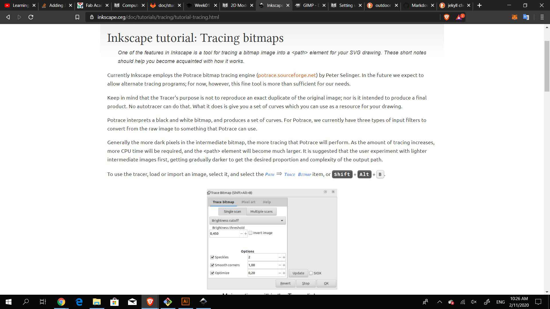
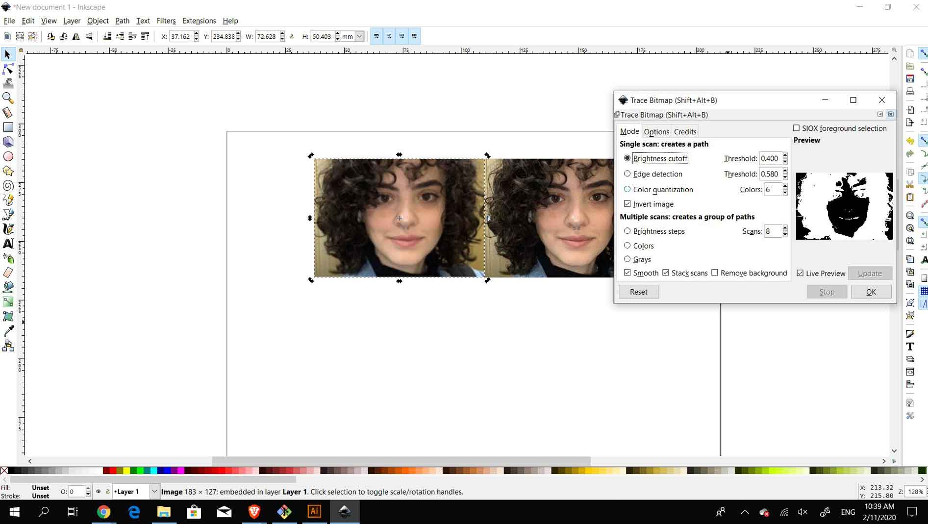
I opened inkscape to begin following the tutorial and imported the image I have used on my "about me" page. I created a bitmap copy of the image by selecting Path --> Trace Bitmap. Or by Shift + Alt + B. Once the Bitmap is created I could now play around with its appearance settings to make it into an avatar.
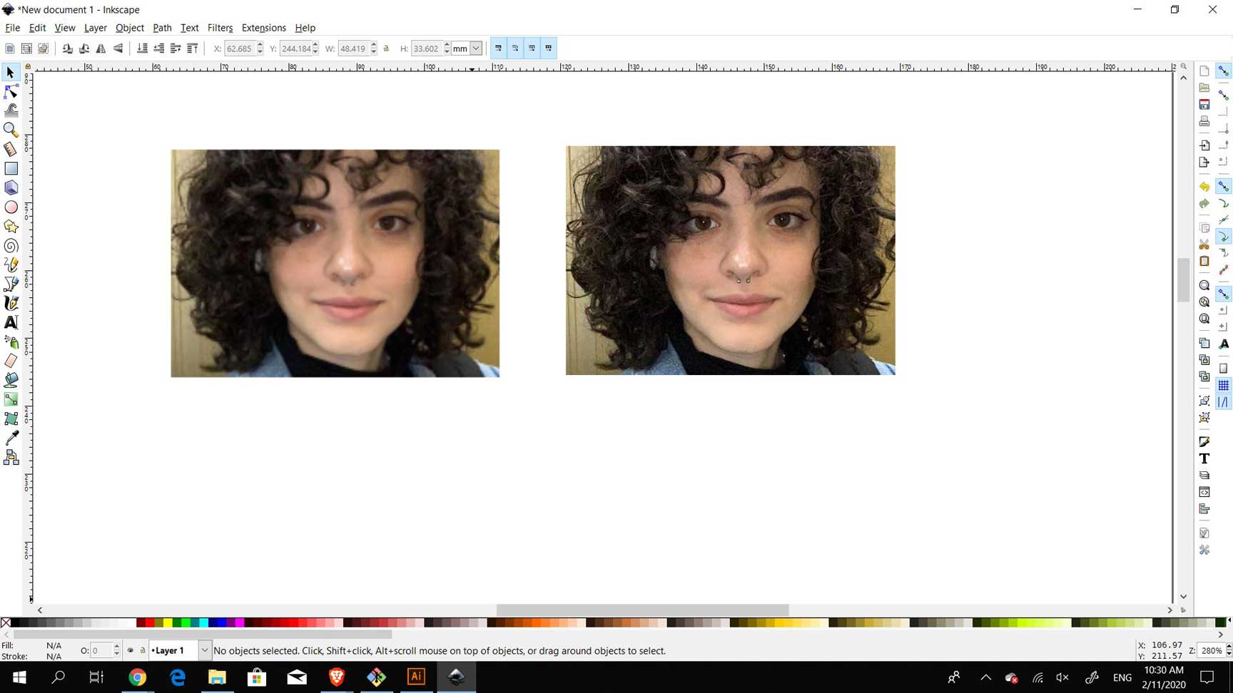
To begin working, I resized the image to be more appropriate for online use. I used the transform tool to be able to scale it up.

I opened the trace window which could also be called for by clicking on shift+alt+B (on windows) and began to play around with the settings, I did not see any changes happening to my image when I clicked okay the first time and couldn't figure out why. I decided to exit outside the trace window and start over.
The problem was that I had not selected the image before opening the settings Bitmap window.. sometimes the most user-friendly programs are the most complicated to use hahahha..
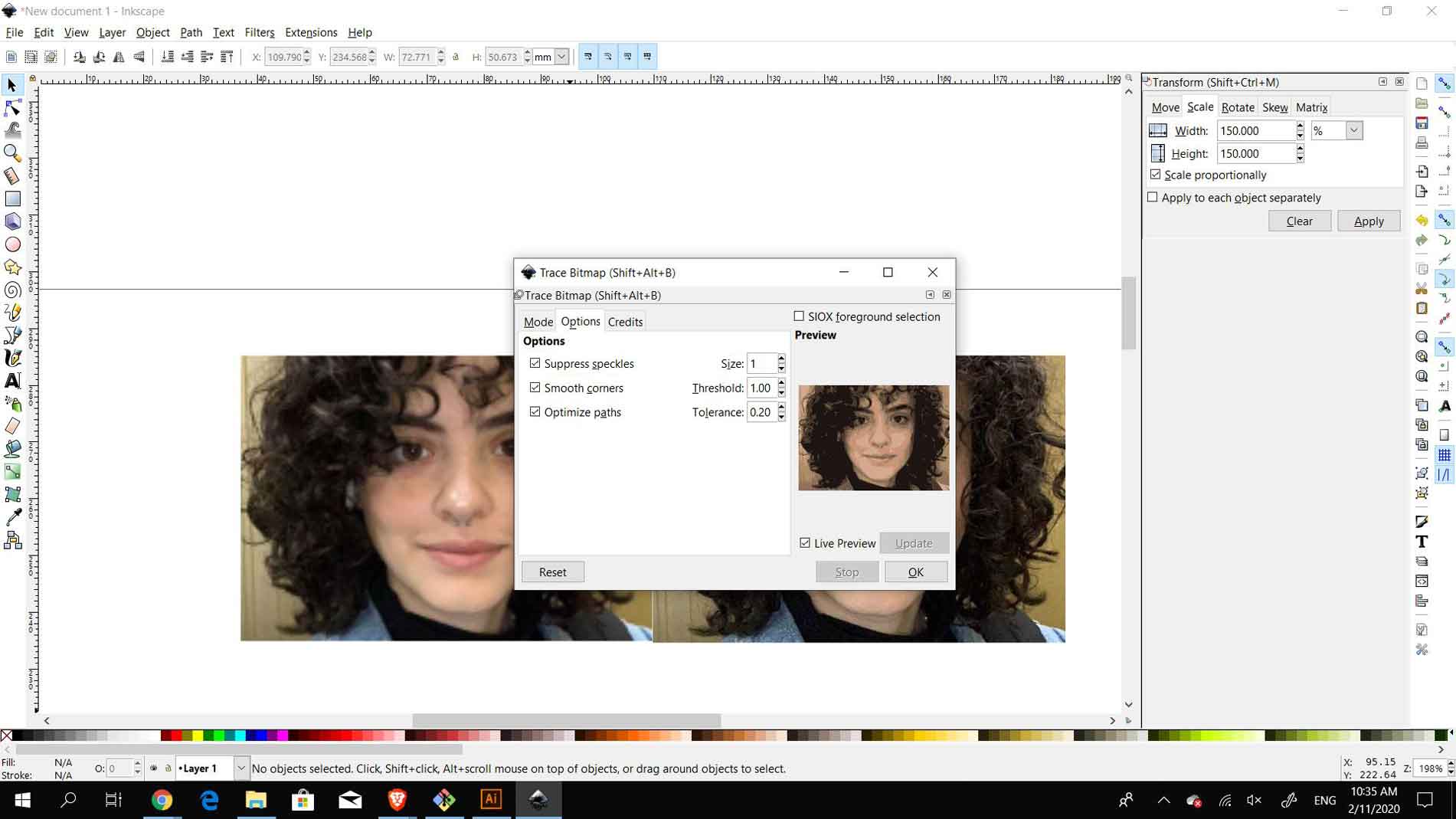
Once I was able to see changes in the settings I began testing what each setting referred to and how to use it.

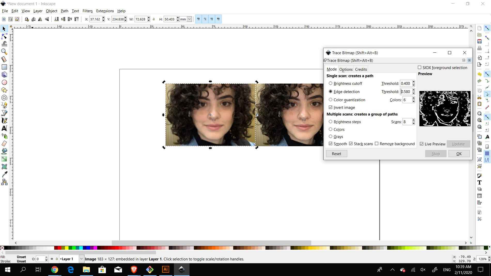
I began to play with the first setting, the quantization. This option will find edges where colors change and outline them. The edges are detected even when different colors have equal brightness and contrast. For this setting you can play around with the number of colors that it detects, the top image detects 8 colors and the botom one detects 6. For the sake of the avatar, quantization is not extremely helpful and so I moved to the next setting.

The next option I played around with was the edge detection. This option detects the curves or edges in the image and highlights them. The way to control this setting is through the slider which has values between 0.0-1.0 which alters the brightness. The brightness is used to detect whether the pixels are on a same curve as the previous one or should be included in the next isocline. The problem with this option is that it may detect curves that are not necessarily important.

The last option is the brightness cutoff. This setting detects the pixels and decides whether they can be grouped closer to white or black according to their hues. The setting control begins at 0.0 (black) and can be scaled up to 1.0 (white). The black to white range slider works where it decides whether the RGB pixels are identified as white or black, the closer to the 1.0 mark the less pixels there will be detected as white.
I then decided to turn my avatar to only shades of grey. The shades of grey setting is controlled by the Scans. So I began to understand the scans and how it would pick the scans according to how many they are.
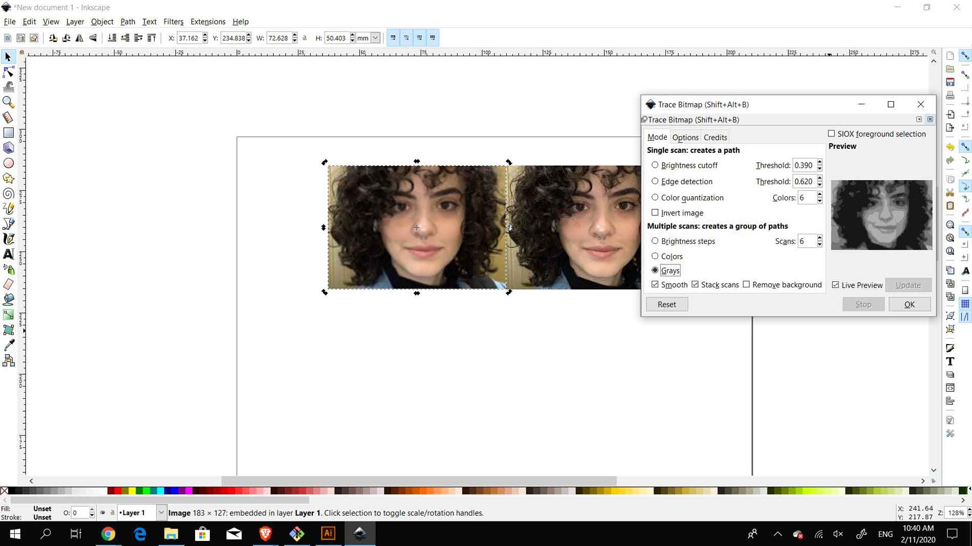
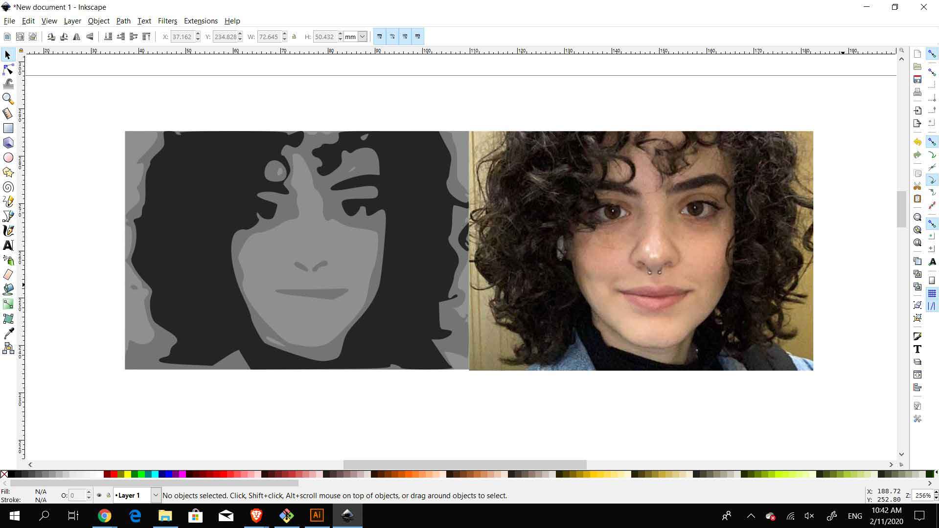
Once only selecting the option of grey, it translates all the BMP colors to different shades of grey. By playing around with the number of scans you can control how many shades of greys and how much detail is shown in the image. I moved down to 3 scans so I could achieve a minimal amount of details while still showing the basic facial features.
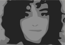
The avatar
2D vector
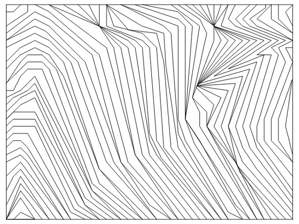
As I am very accustomed to 2D vectors, I wanted to try something interesting and for the fun of learning a new tool. I wanted to recreate a drawing I always make by hand when I am focused on other things, as I am a auditory learner. It is a series of polylines following each others angles.
I wanted to work with Qcad as I have never heard of it prior to the class this week. I downloaded the free trial and began to experiment with the polylines. At first glance the controls and movements seemed quite close to AutoCAD, along with the grid snapping option. I began to draw a number of lines to test out the snapping and I found that the grid is very helpful as it snaps to it directly and so it makes it easier to work with precision. One worry was that the lines would snap to one another rather than to the grid, however, it did not happen in my case.
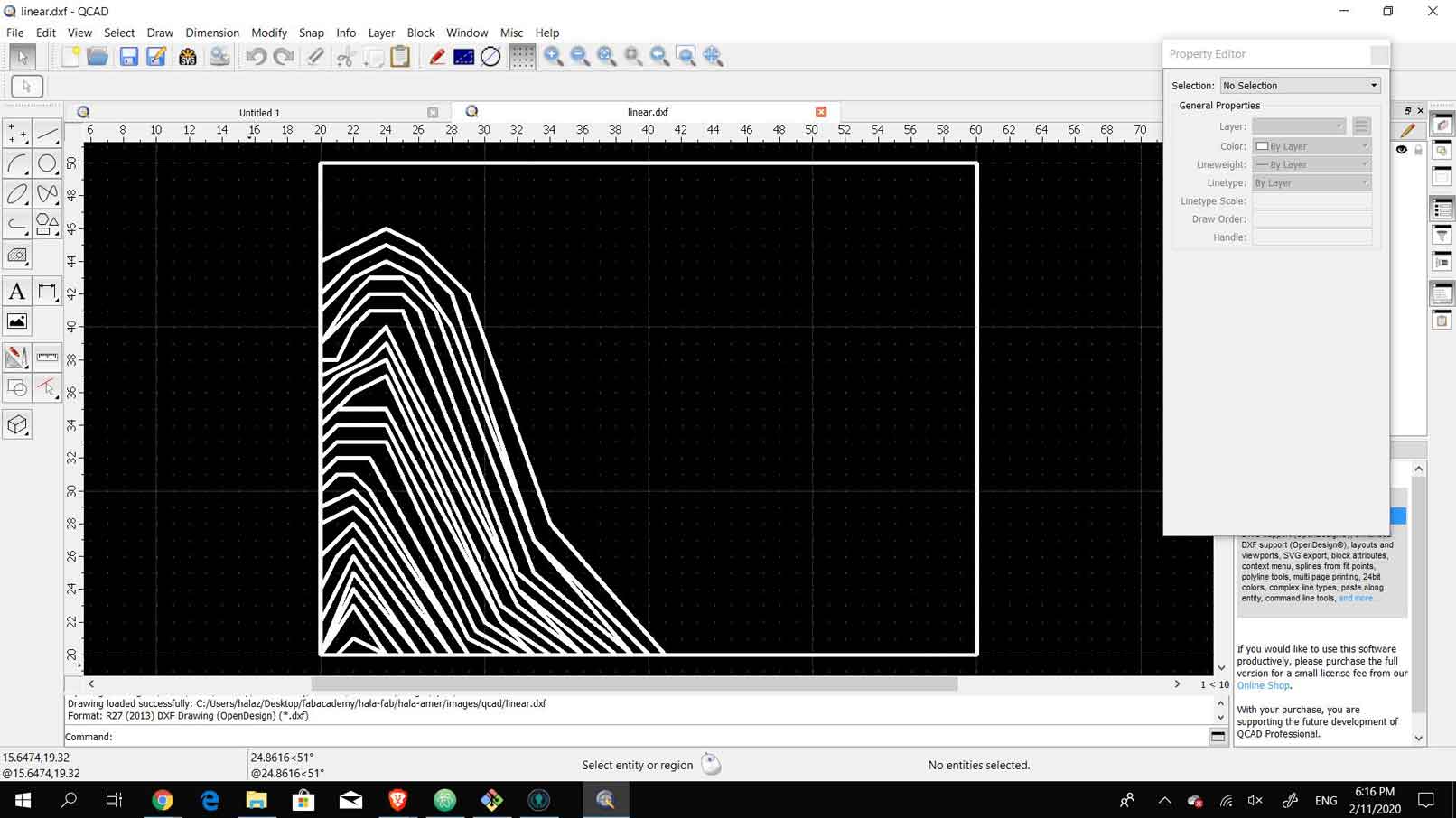
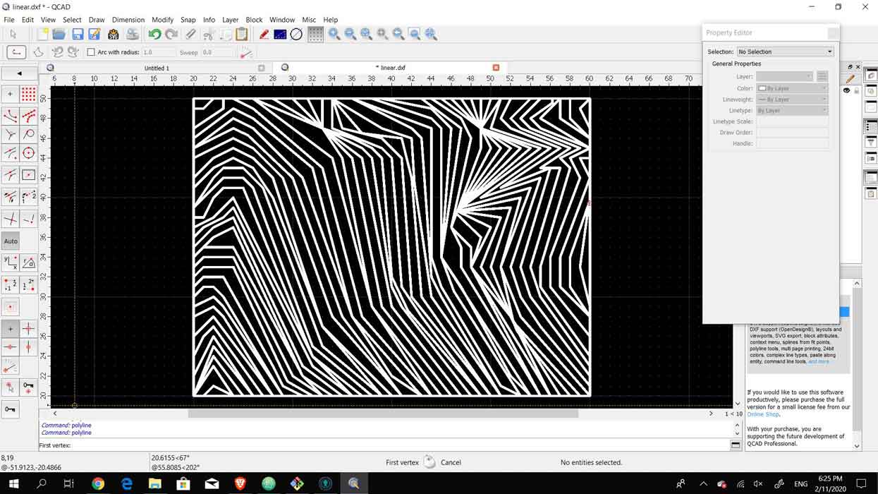
When all the lines were complete I realized that the lineweights seemed large and found that I had been working on an extremely small scale. As I was happy with the illusion that came out I sclaed it up so it is more proportional with the lineweight. Once it was scaled up, the lineweight was more precise and the overall polylines looked much neater.
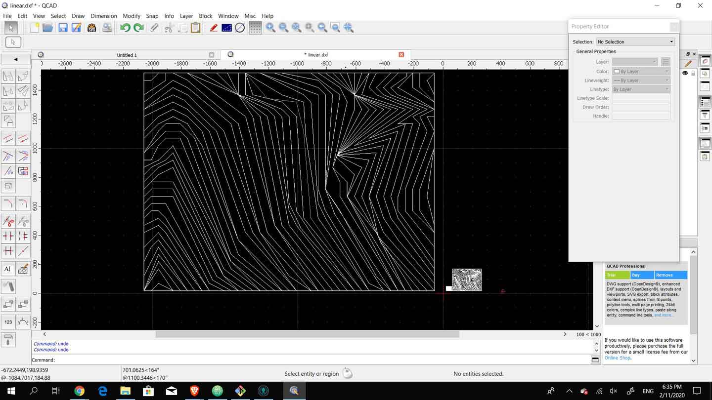
In the modify tab there is the scaling option. The option works by selecting the factor of scaling and then selecting the base point to scale from. I scaled twice before reaching an adequate size for the image as I am thinking of using this image for the thumbnails of the weeks on my website. After I was pleased with the overall look and the ploylines I checked whether they were all joined correctly and whether there were any overlapping lines that needed to be trimmed. As these lines were easy to draw with the help of the grid I did not need to edit much and I was able to directly export as svg and a png.
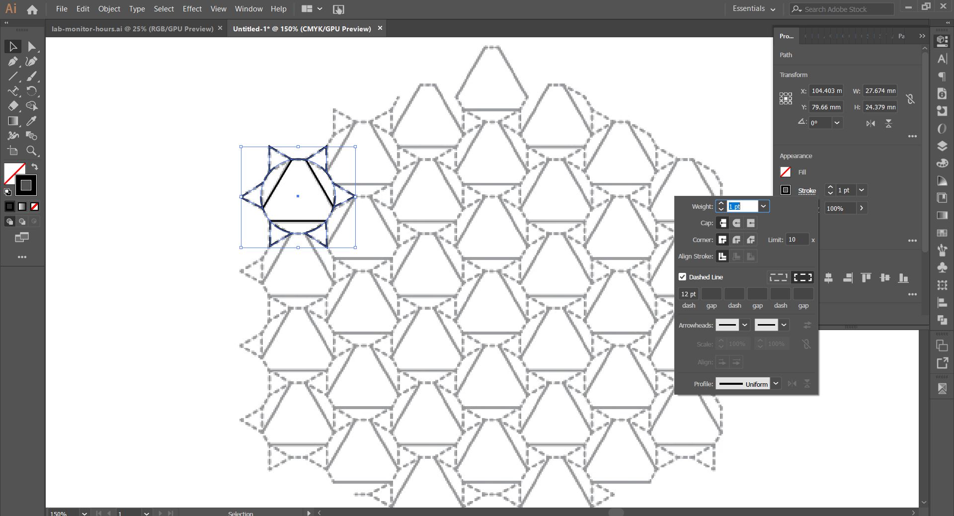
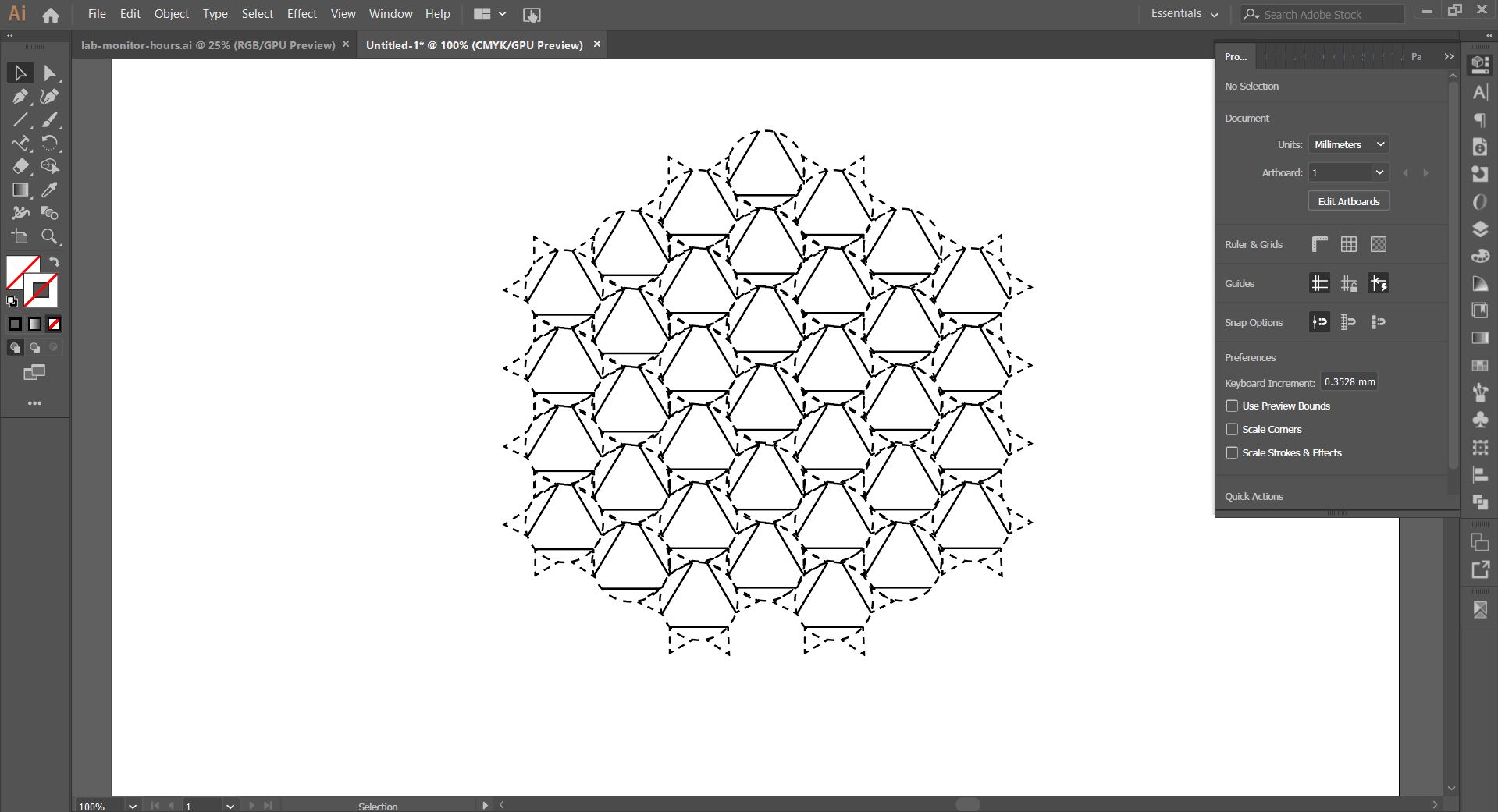
Folding PatternFor Final Book
Below are the steps to create the pattern that was developed by Astrid in her FabAcademy Project.
Step 1
Step 2
Step 3
Step 4
Step 5
Step 6
3D modeling - Grasshopper
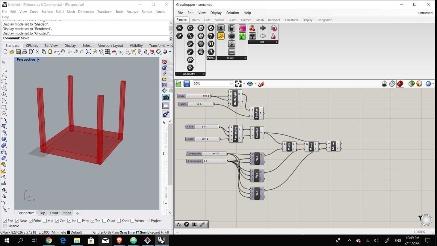
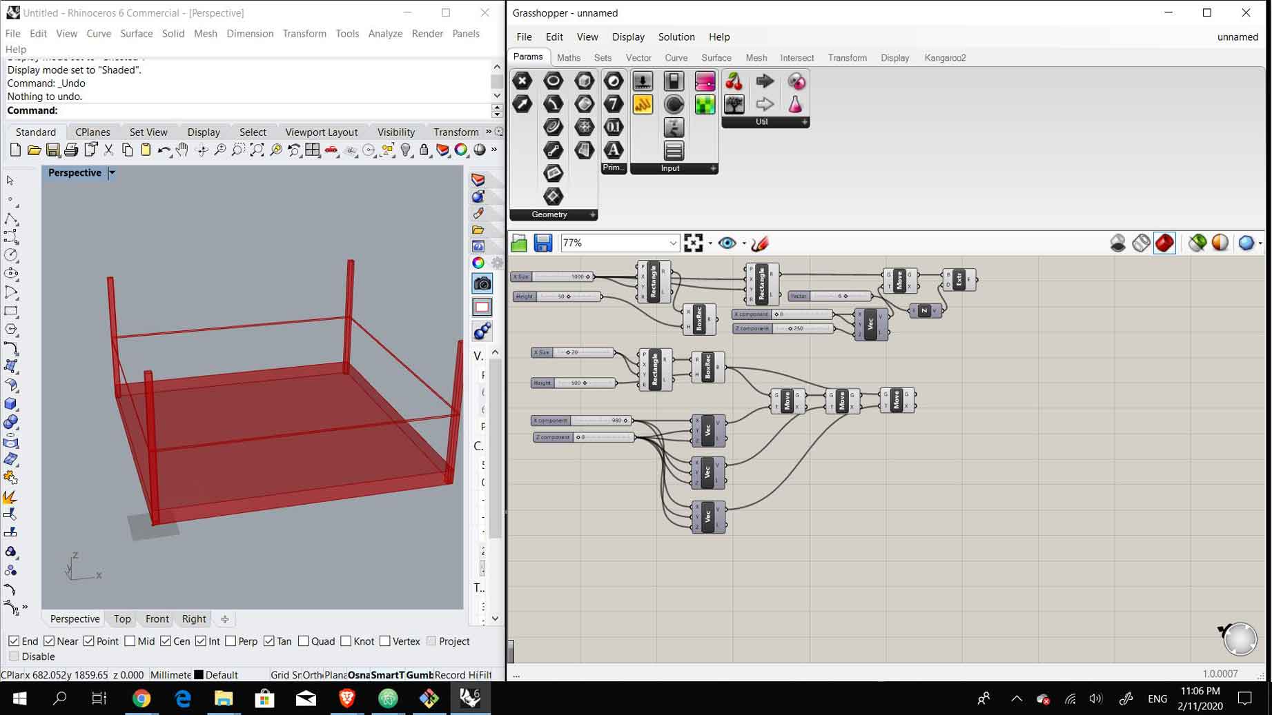
Grasshopper has been one of those 3D Modeling softwares that are very intimidating to begin using and I have kept pushing learning it. As a first timer, I watched a number of youtube videos and tutorials to understand the basic algorithm. As a learning exercise I decided to make something extremely simple that might be beneficial regardless what the final project will turn out to be. I began to model a basic rectangular base that could either host the vinyl sheets, if I were to continue working on a vinyl cutter, or the mechanical parts that will be attached.
Grasshopper sometimes seems to be a little intuitive with the order of the commands and others seems very illogical. It was very difficult to understand the order of the commands and how they affect each other as the order is completely different from basic Rhino. For this first exercise it was more of a matter of logic and guessing to know which components to place and how to connect them.
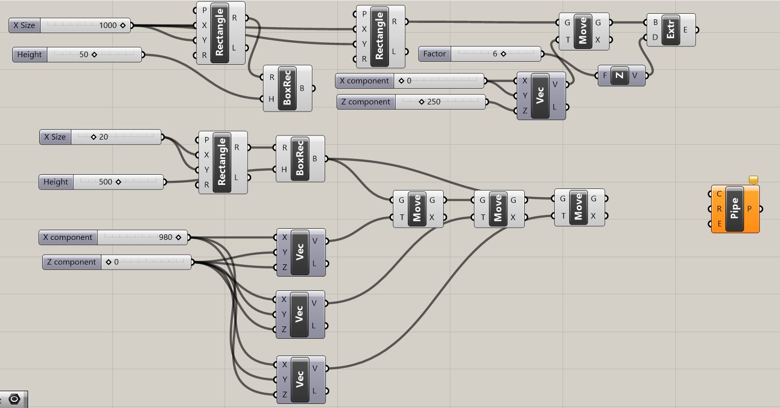
I began by drawing a rectangle with its x and y dimensions, 500 mm, as a base for the box. Once the base was done I began working on the extrusions that would be at the corners. I drew a square at the xyz 0 and extruded it to a height of 500 mm. Then I used the "move" component and moved it 4 times to fit inside the corners of the base box.
Once that was done, I decided to add another bounding component at the midpoints of the extrusions for safety purposes in the future of the project. I drew a rectangle and moved it up to be at the midpoint of the extrusions. Sidenote: While modeling I found that one component that was difficult to use yet would be helpful is the boolean as it had many inputs and outputs.
In my years of education and working I have modeled with Rhino extensively and it was always extremely annoying to model for fabrication and then test and realize that tolerances needed to be changed. When I was able to easily change all the dimensions with a few slides I realized how much my laziness has prevented me from achieving.
The next step was to turn the rectangle, that I moved to the midpoint of the vertical columns, into pipes or curved edges. In the case that the fina project is the vinyl cutter this pipe would be used to attach the gears that will move the knife. I found a tutorial on youtube made by Archi Glass that shows you how to customize pipe shapes instead of following the pipe command. I tried to follow the steps in the tutorial to turn that rectangle into the pipes. Once I was able to achieve that I decided to render it without any more additions.
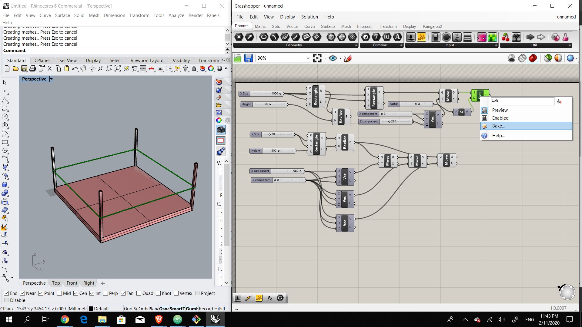
To render the base, I baked all the components. I'm not a big fan of the rendering options in Rhino as it is not the easiest, in my opinion, and so I exported the model into Fusion 360 to render it from there. I used the existing material library in Fusion 360, using plywood as it is what is available in the FabLab and rendered it. The final result is a very basic squared base with extruded corners as I have not designed the final project idea yet.
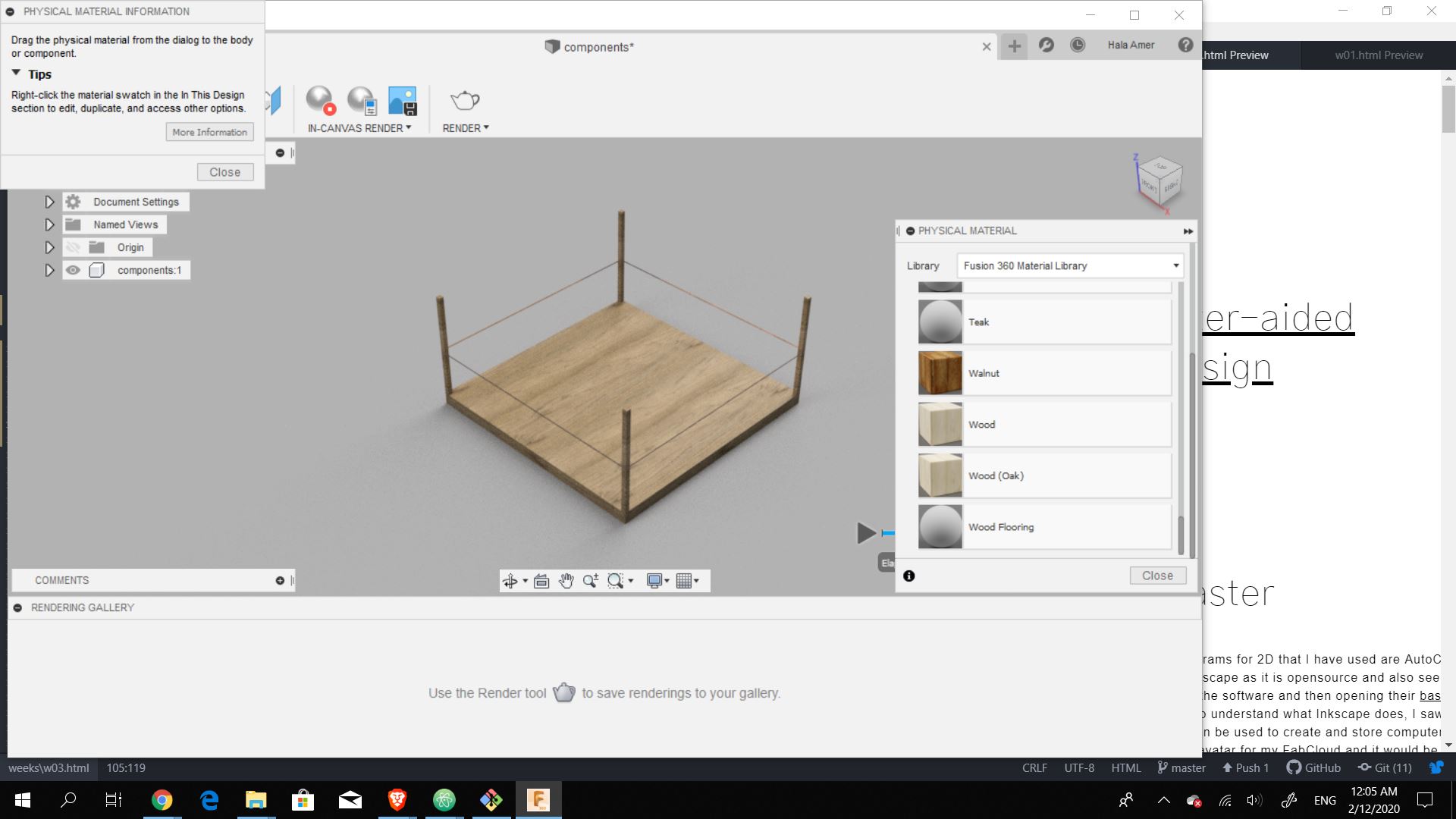
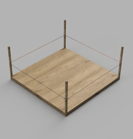
The final rendered object
Final Thoughts
While deciding what to model I realized that my idea for the project is no where near defined and I would need to think about it further to integrate the weeks for the purpose of testing the project. Using grasshopper will be beneficial yet it needs a lot of experimenting and learning to reach a point where I am more comfortable designing in it than Rhino. As for Qcad and Inkscape, I did not enjoy using them as I am more accustomed to the Adobe softwares and I understand their logic better.
Files