7. Electronics design
The objective of this week is to first, work with a group to observe the operation of a microcontroller circuit board like the operating voltage and to check noise of operating voltage and interpret a data signal by the oscilloscope, second to Individually, to Redraw one of the echo hello-world boards, add an input and output devices, check the design rules.
Group Assignment
You can find our group assignment in this link
PCB Schematic Design
For this week to accomplish the objectives I chose to redraw the PCB of the ATtiny44. I started by downloading eagle as it is an open source from Autodesk.
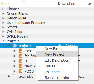
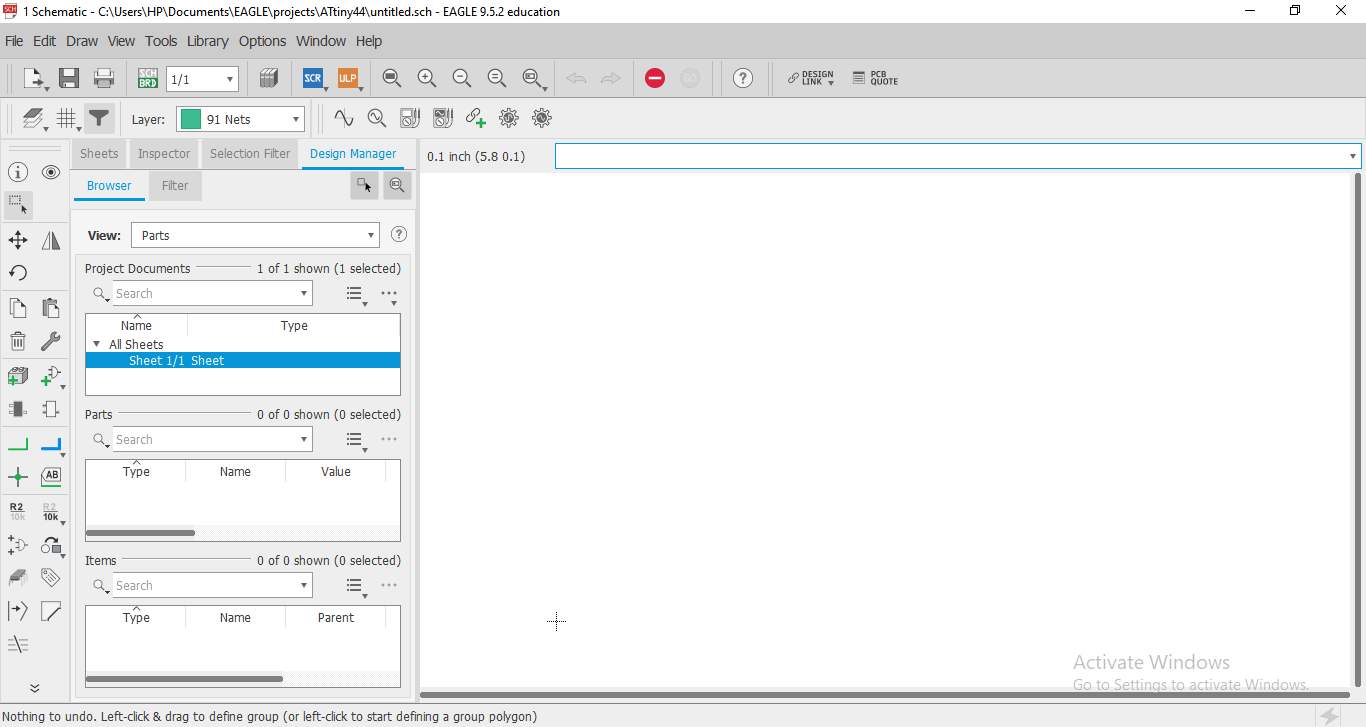
To start a drawing the PCB, open Eagle the following window will be shown, highlight the project bar and click the right click in your mouse and select new project. Once you select new project again highlight the new project, right click << new << Schematic, a new window will be open for you.
It is important to add the fab library, so to do this follow the following steps:
- Download the library from the link above.
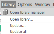
- click on the library list which is shown in the toolbar to open the library manger.
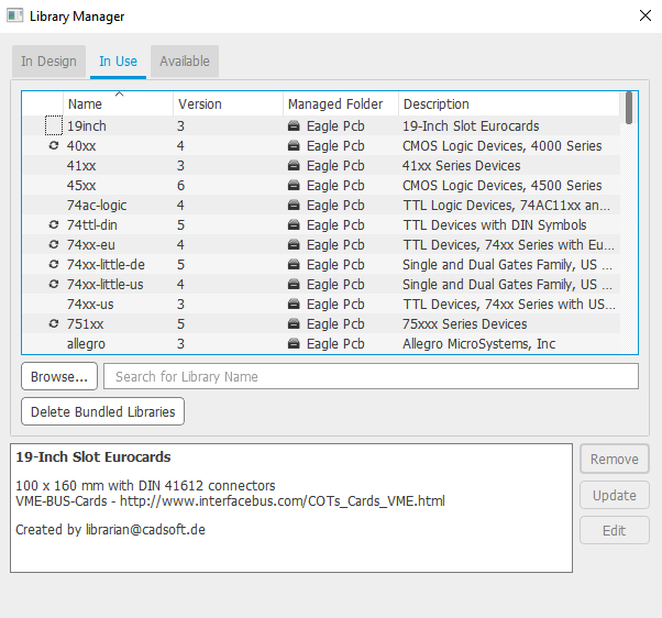
- In the library manger select ‘in use’ << Browse to the location of the fab library << open << update.
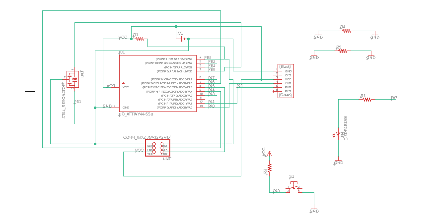
Once I have done with the adding the library, I insert all the PCB parts by clicking on add parts icon.

After that I route the parts by using the net tool and the label tool to avoid disorgnized wires, both the net and the label tools are in the lift toolbar.

The final result for PCB Schematic is shown in the pictuer below
PCB Design
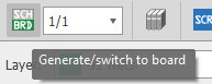
To design the board, I need to switch from Schematic design so I click on Generate/switch to board icon.
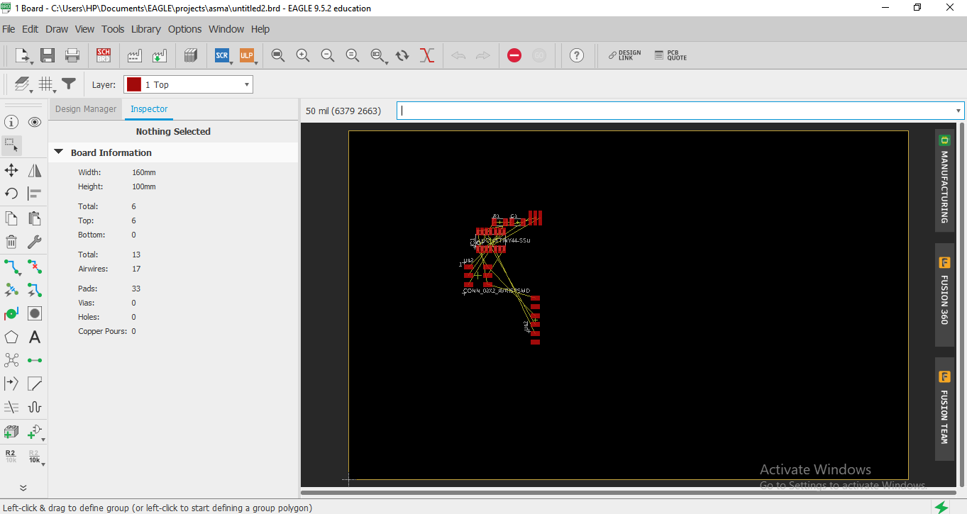
A new window will open with the circuit component so we can organize the traces between the component without any intersection.
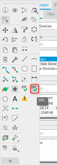
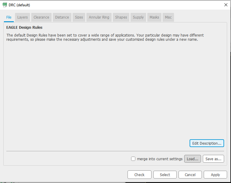
However, it is important to add the design rules for the PCB to ensure that the design will be with no error when we transfer it to the milling machine. To add the design rules, I need first to download them from this link and then click on the DCR icon << load, to select the design rule file << apply. It is also important to check the clearance and change it to 16 mill.
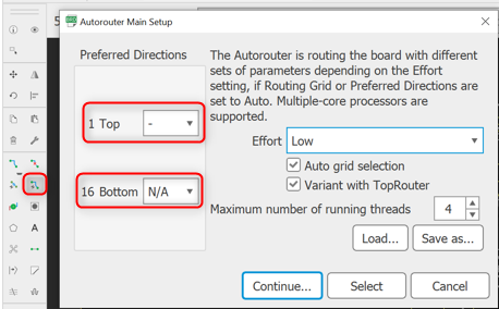
To make autoroute. Set to top layer only and do the following set ups:
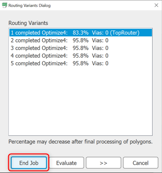
The result of autoroute was not as expected it gives me like 95% connected precentage which lead to some errors or many unconnected traces, so I decided to rout the component by myself by using the route airwire tools and by changing some components places repeatedly until I figure out some tips like adding the jumper resistor to be able to connect some traces under it. I did not like this process as it is consumed a lot of time to adjust and connect the traces without any interaction. In the end, I used two jumper resistor to be able to connect all the component
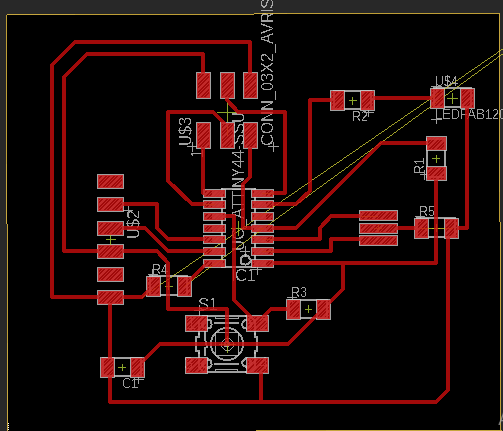
The final result for the PCB design is in the picture below
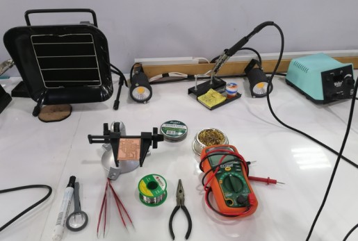
Milling and soldring
To export the file and send it to the milling machine follow the following step:
-
move the yellow line and drag it to edit the size of the board border
-
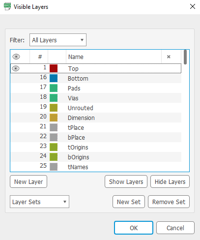
click on the layer icon and hide all the layer by clicking on the hide layer button, then highlight the desired layer for me it was the top and click on the show layers button.
-
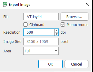
go to file << export << Image.
-
select the name of the image, change the resolution from 150 dpi to 500 dpi and check the Monochrome box to make the image black and white.
- repet the previouse stepes with the PCB yellow border but keep in minde that the yellow lines Width should be equal to 31.25 mils, to do this just select the line << right click << properties << width.
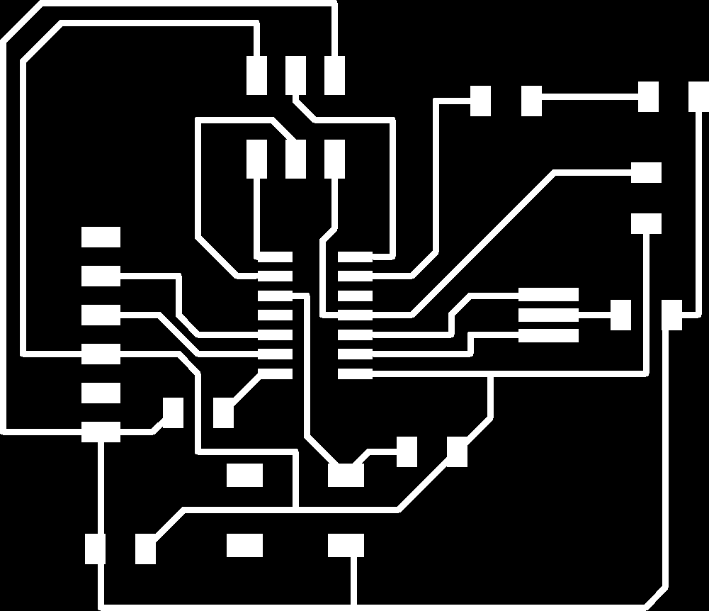
The final result of exporting both the PCB and the border is shown below

After exporting the PCB from Eagle we should Convert the png files to rml file that the milling machine could read, To do this follow the steps below:
-
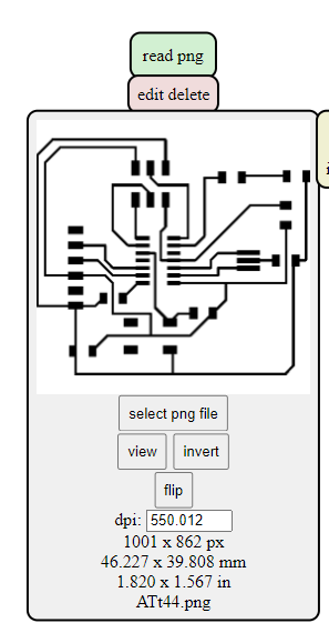
open Mods << right click on the empty white space<< programs << open server program << PCB png.
-
In the read png window click on the select png button and browse to the PCB image and invert it so the traces will be Black.
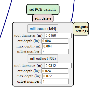
- Go to set PCB defaults window and click on set mill traces (1/64).
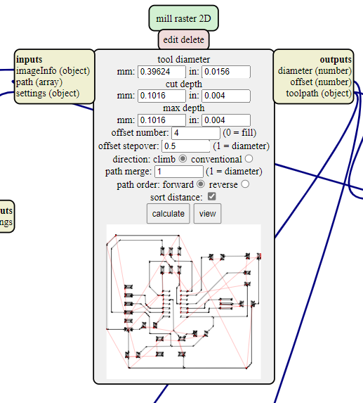
- Go to mill raster 2D and press on calculates button, once you press it a default rml file start downloading.
-
Repeat all the previous steps to generate the rml file to the PCB border but keep in mind to change the selection in step 3 to mill outline.
-
open the downloaded rml file in the SRM-20 milling machine software, it is important to change the milling bit to 1/64 for the PCB traces and 1/32 for the border.
-
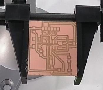
Adjust your x, y, z origins by using the cursor on the software and set up the milling speed. Finally click cut to start milling the PCB and do the same for the border but don not forget to re-origin the starting point by keeping x and y the same and readjust the z point manually.
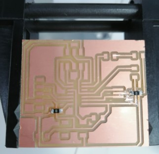
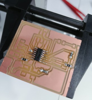
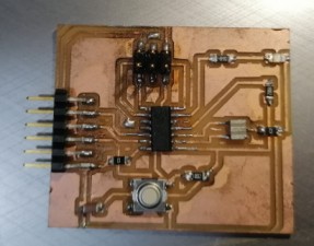
The final results is shown below
Finally I started to solder the circuit components.
Programming
To program my PCB I follow the following steps : 1. connect the PCB with Fab ISP by using FTD and USB cables.
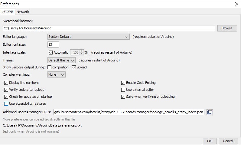
- open Arduino IDE << file << preferences << Additional Board Managers url and paste this link.
-
from the toolbar go to tools << Board << Board manger, once you select board manger a new window will open for you, search for ATtiny and install the board library. The aim of this step is to add the ATtiny44 to the boards in Arduino IDE
-
Setup the software to program my board by :
- Select the board From the toolbar go to Tools << Board << ATtiny 24/44/84 << ATtiny44.
- Select the processor From the toolbar go to Tools << processor << ATtiny44.
-
Program the Arduino From the toolbar go to Tools << clock << External 20 MHz .
-
Again from tools << Burn Bootloader.
You should see the message “Done burning bootloader.””
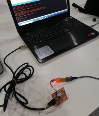
Testing
To do this I just upload a simple blinking code
void setup() {
  pinMode(PA7, OUTPUT);
}

// the loop function runs over and over again forever
void loop() {
  digitalWrite(PA7, HIGH);
  delay(1000);
  digitalWrite(PA7, LOW);
  delay(1000);
}
The result is shown in the video