Assignment 9: Molding and Casting
Project Description
Design, mold and cast something
Assignment Details
- Group Assignment:
- Review the safety data sheets for each of your molding and casting materials, then make and compare test casts with each of them
- Individual assignment:
- Design a 3D mold around the stock and tooling that you'll be using
- Mill it, and use it to cast parts
The objective for this week was to cast parts needed to make a jog controller for the Final Project Pumpkin CNC. The figure below shows the soft buttons on the left and the hard case on the right. In the spirit of iterative (spiral) development I decided to start with the soft part on the left.
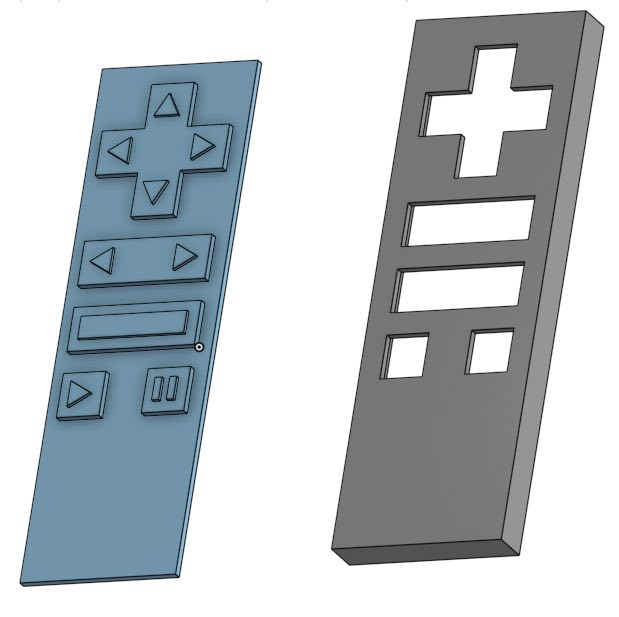
First I cut a sample part out of soft material to validate the design. After doing this I noticed that the raised operation indicators (Up, Down, In, Out, Play, Stop, Pause) were hard to see, so I increased the thickness of the layer in the CAD.
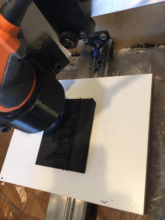
The person that I was working with at my local Makerspace suggested that I create a negative CAD part of my positive CAD part and mill that as my mold. After completing the milling, the 1/8" bit was not small enough to cut the operation indicators on the buttons. My class mentor also let me know that milling just the negative mold would not meet the class requirements. He also indicated that the part needed to have 3D contours (2.5D would not meet the requirements).
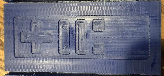
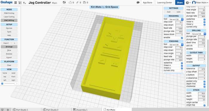
After finding out that the milling the positive 3D mold of the part was required, I generated a new CAD part for this mold. The figure below shows the feeds and speeds for the milling operations. The key item to note is the selection of ""Linear X and "Linear Y" in the Finishing section. These selections generate the 3D X and Y contour cutting operations.
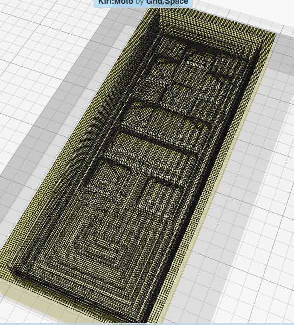
The figure below shows a simulation of the G-Code tool paths. This shows the 3D finishing paths that result in the 3D contours.
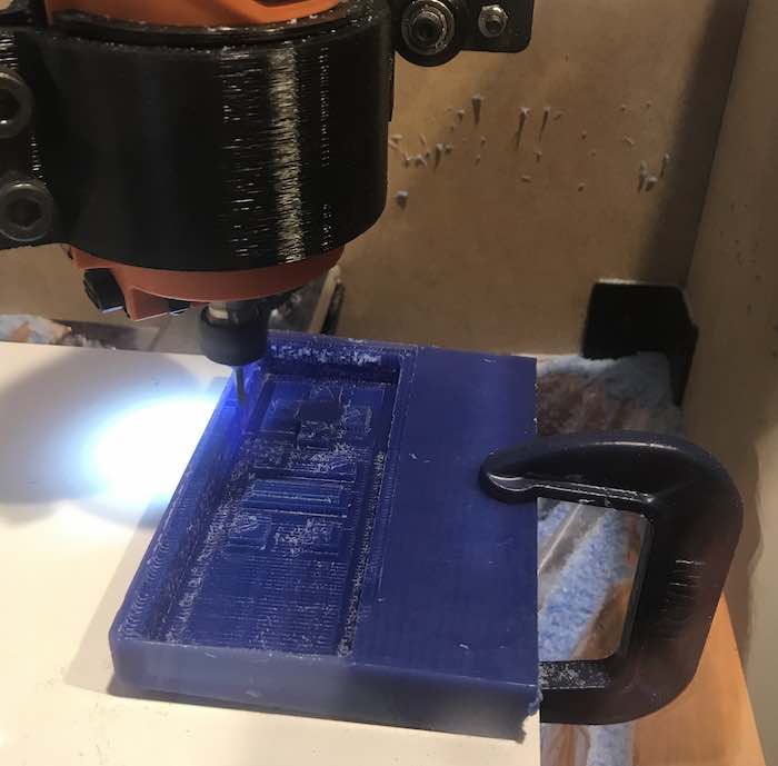
I went back to the CAD and designed a positive mold. The figure below shows milling this mold out of machinable wax.
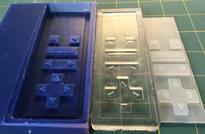
This picture shows the machined positive mold and the resulting negative mold made from hard casting resin. I estimated the volume of casting resin by filling the mold with water and then measuring the water. I referred to the Product Data Sheet to determine the ratio needed for the catalyst and estimated cure time.
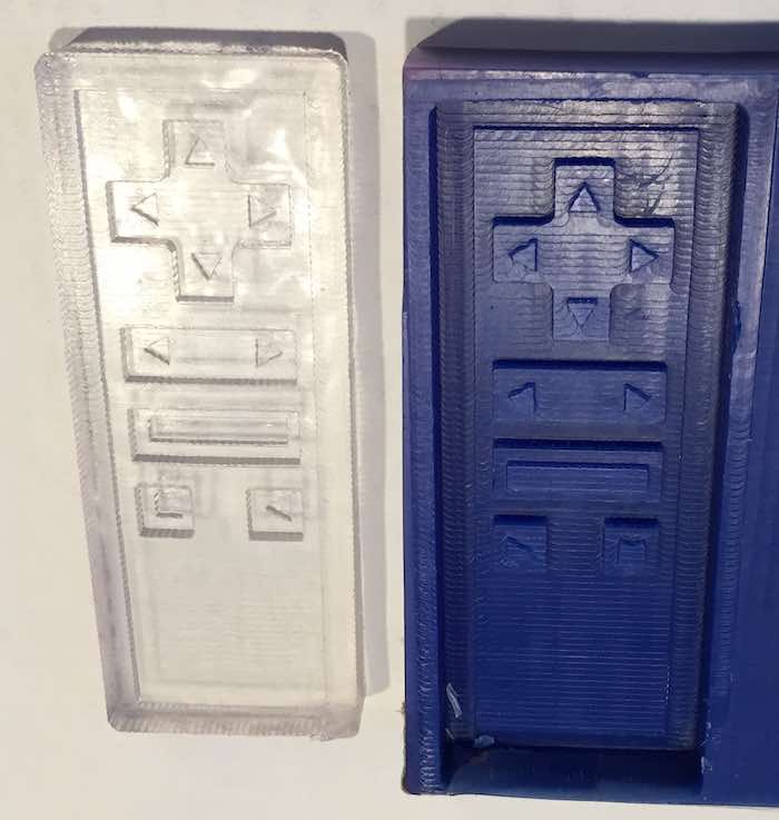
The last step was to cast the final piece. Again I estimated the required amount of silicone by measuring water filling the mold. I mixed the silicone with the catalyst and filled the mold. The silicone is curing very slowly. I suspect that I didn't add enough catalyst to the mix.
After 48 hours of curing the soft part finally cured enough to remove from the mold.

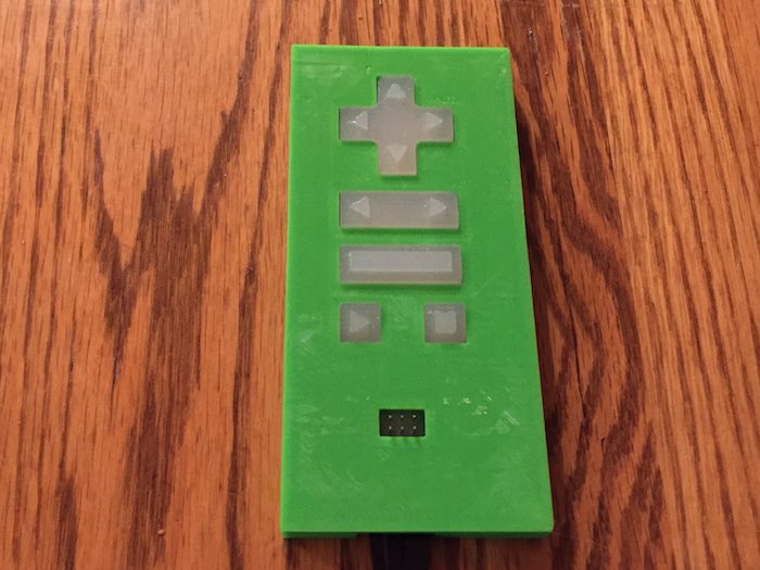
The following figure shows the finished Jog Controller Assembly
Lessons Learned
- Molding and casting takes a lot of time (specifically curing): I created my first CAD design on Wednesday, but still ran out of time. The first cure took 24 hours and the second took about 48 hours. The stack up of dependent cure times across both molds was much longer than expected. I ran out of time to build the second part.
- The weight of the paper cup can be significant when casting small amounts of material: The instructions indicated that the catalyst was 1:10 by weight. My total pure was about 30 grams, so this meant that I needed 3 grams of catalyst. I weighed 3 grams of catalyst, but this included the weight of the paper cup, so I likely added less than recommended. This may have resulting in a longer than expected cure time.
- Rubber gloves are great: Molding and casting gets messy. Having the ability to just pull the rubber gloves off, means less personal clean up when done.
