11. Input devices
Assignment
Measure something :
- add a sensor to a microcontroller board that you have designed
- and read it
Sensor type
For my final project, I want to measure fine particles concentration in air.
I already achieved to use the SEN0177 air quality sensor (that is just a Bjhike HK-A5 with a level translator) but, later I found this paper proving that it’s not accurate outside of the PM2.5 range.
For this reason, I want to try making it myself. Of course, it won’t be more accurate.
I found some interesting documentation there :
Input device
I’m thinking about using a LED as a light sensor because it may be cheaper and easier to find than a phototransistor. I already tried it to detect a LASER beam and it worked fine.
It also have the advantage to do color discrimination. It may be usefull when it comes to measure the particle size, according to the light wavelenght.
Design
3D printed case
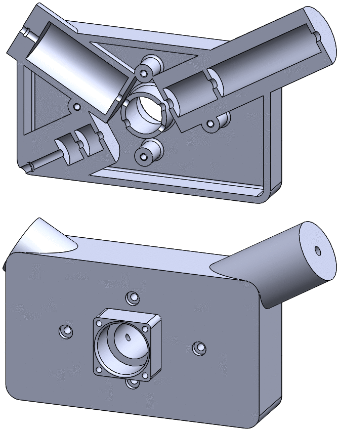
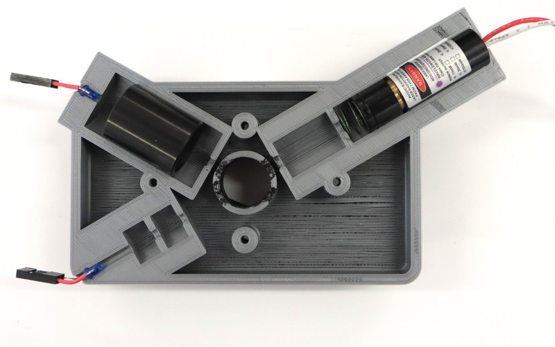
I designed a case in SolidWorks. It should get the LASER aligned with a first LED, and a second LED aligned with a lens (that I’ve found in a scanner).
The first LED allows measurement of transmitted light, the second one is for 30° reflected light.
I started modeling the entire case, then I cut it in two parts :
This is how it looks with the optics :
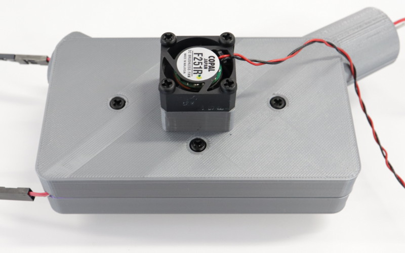
And when the case is assembled :
Adapter board
Here is the board that I will use as an interface between my HelloBoard, the LEDs and the LASER module :
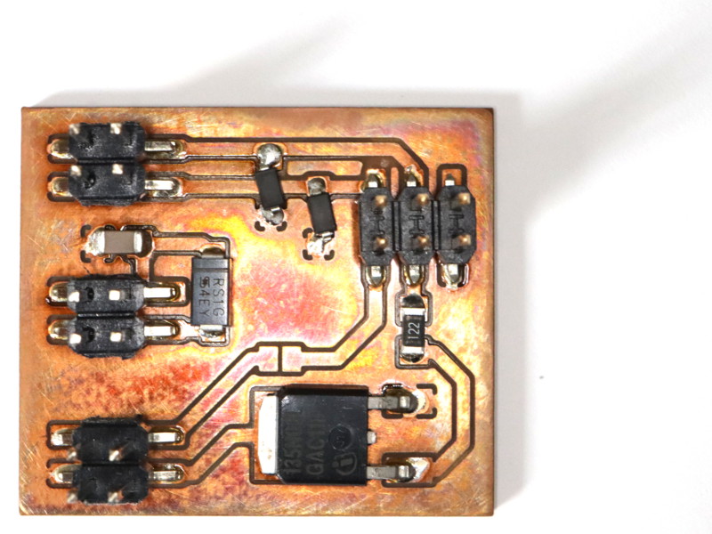
It uses a MOSFET for turning the LASER on, and two zener diodes to protect the microcontroller inputs. It has a 6 pins header that should allow connection to the ISP connector of the HelloBoard.
But I made a mistake (the 6-pin header was mirrored) so I had to do it again, in order to allow an easy connection to my HelloBoard.
Here is the new design :
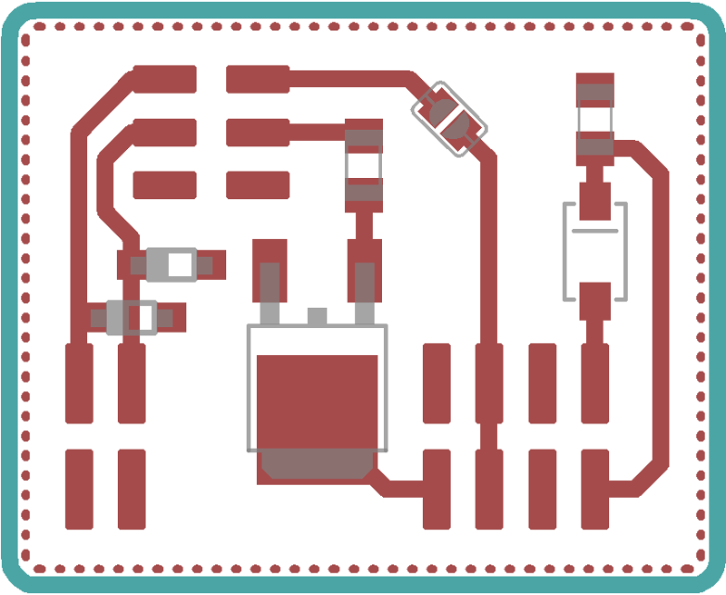
I used reflow solder because the MOSFET needs a proper soldering of its thermal pad and it’s hard to achieve it manually. Here is the PCB with solder paste and components :
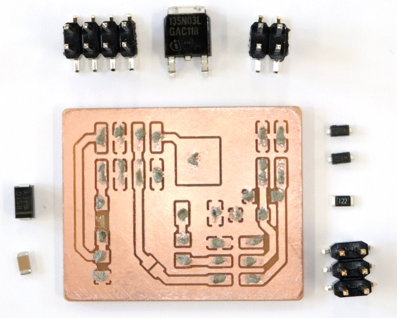
And after placing components, before reflow :
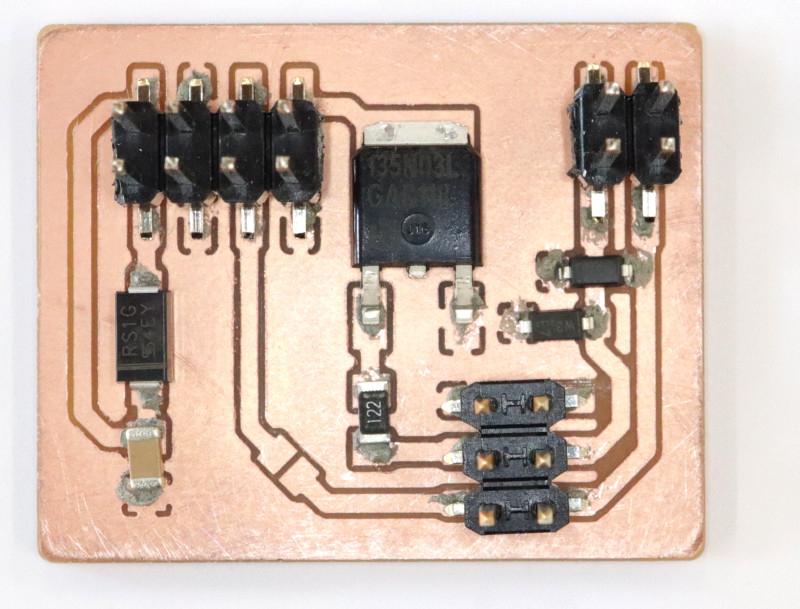
And after reflow soldering, connected to my HelloBoard :

LASER control
I want to switch the MOSFET at a specific frequency so I need to use a timer. So I looked for an online AVR timer calculator and here is the code that I got (I just had to change the output pin):
// v. 8
// http://www.arduinoslovakia.eu/application/timer-calculator
// Microcontroller: ATtiny84
// Created: 2019-04-10T12:31:41.308Z

#define outPin 6

void setupTimer1() {
  noInterrupts();
  // Clear registers
  TCCR1A = 0;
  TCCR1B = 0;
  TCNT1 = 0;

  // 100 Hz (20000000/((3124+1)*64))
  OCR1A = 3124;
  // CTC
  TCCR1B |= (1 << WGM12);
  // Prescaler 64
  TCCR1B |= (1 << CS11) | (1 << CS10);
  // Output Compare Match A Interrupt Enable
  TIMSK1 |= (1 << OCIE1A);
  interrupts();
}

void setup() {
  pinMode(outPin, OUTPUT);
  setupTimer1();
}

void loop() {
}

ISR(TIMER1_COMPA_vect) {
  digitalWrite(outPin, digitalRead(outPin) ^ 1);
}
I tried to upload it to my HelloBoard using Arduino IDE… And it did not work. I still don’t understand why.
Timer configuration
I found this website that gives a good explanation of how to set the timer frequency for the Attiny84. I used it to interface my Python application (week 16) with output devices.
Testing
Transmission test
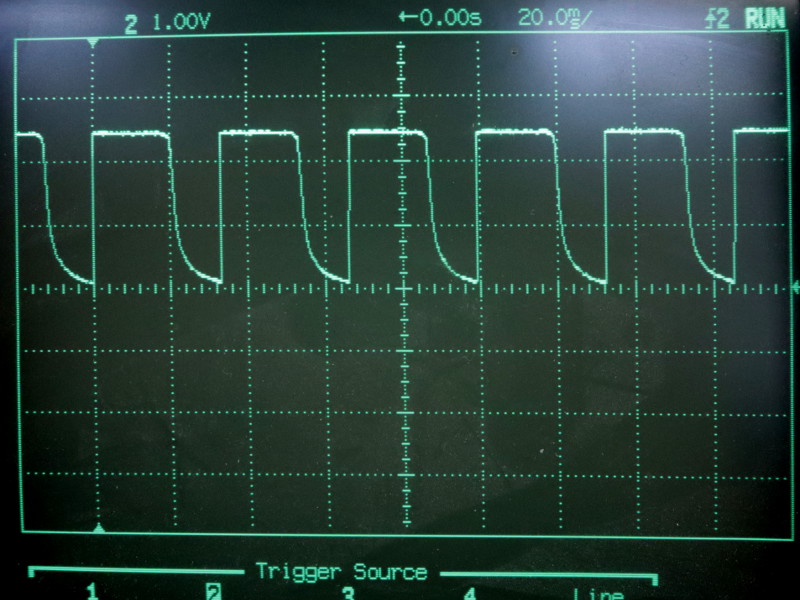
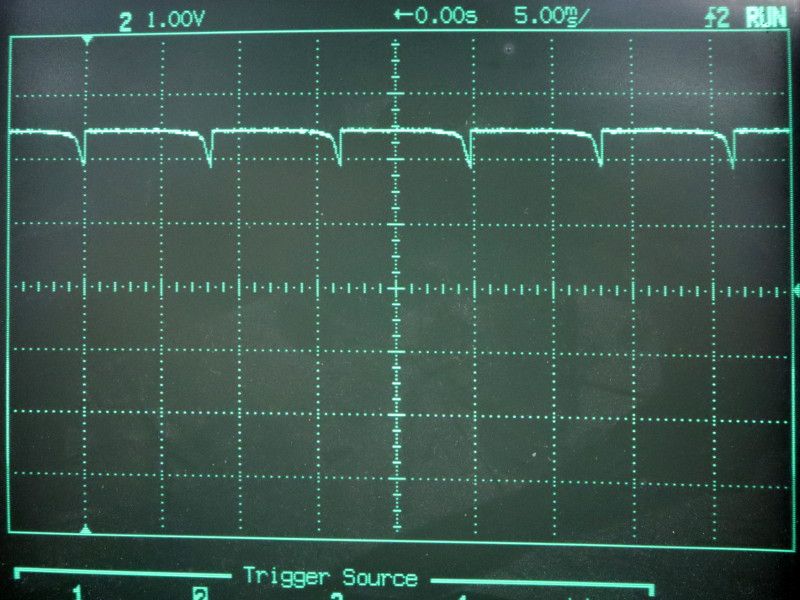
In order to find the duration of the shortest transmissible impulsion, I used a signal generator to control the LASER and an analog oscilloscope to see the voltage drop across the LED.
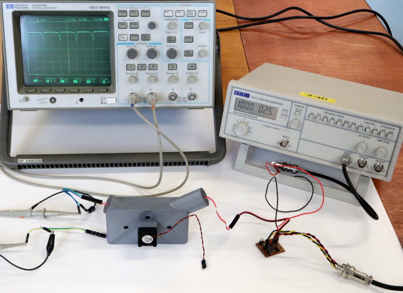
It is far from perfect because the wires add capacitance to the system. Let’s try to get some data anyway.
At 30Hz, the received signal is showing a falling curve but it still have this nice 2.5 volt drop :
At 100Hz, the signal has less amplitude but voltage drop is still close to 1,5 volt :
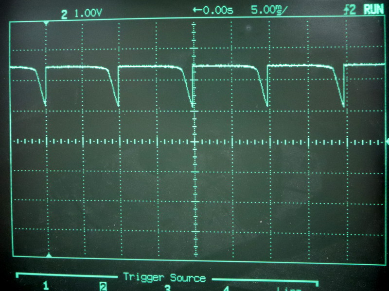
If inverted, the signal has enough amplitude to drive a microcontroller input.
At 120Hz, peaks are so short that I would not rely on it for measurement :
Reflection test
I did not achieved to get a signal from reflected light, maybe it would work with an amplifier…
CAD files
- Optical sensor case Solidworks part, STL and g-code
- Adapter board EAGLE schematic and board
Water level sensor
For my final project, I made a simple water sensor made of two wires :
- The first one will be turned on (to 5v) when starting a measurement.
- The second one is connected to the ADC, with a pull-down resistor.

The pull-down resistor value must be greater than water’s resistance. Here, I used a 1MΩ resistor.
Adapter board
There are 3 connectors on the bottom of this board :
- A 6-pins SPI socket, to be plugged on my HelloBoard (or another Arduino board).
- A 2-pins header, for the 5v supply.
- A 5-pins socket, for a relay module.
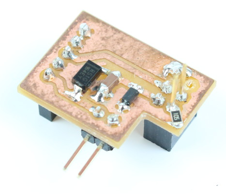
On the top side, there are two pins rising from the 6-pins SPI socket. This is where the water sensor is connected (to PA4 and PA5).
At first, I wanted to make a capacitive sensor using the step response example code. But the wires going from the tank to the controller board were too long for a clean capacitive sensing, so I decided to make a resistive sensor out of it.
This is why the pull-down resistor on the ADC input signal was not in the original board design :
HelloBoard code
Then, I flashed my HelloBoard with this Arduino code.
It will light the blue LED if there is water to conduct electricity. If not, it will light the red LED :
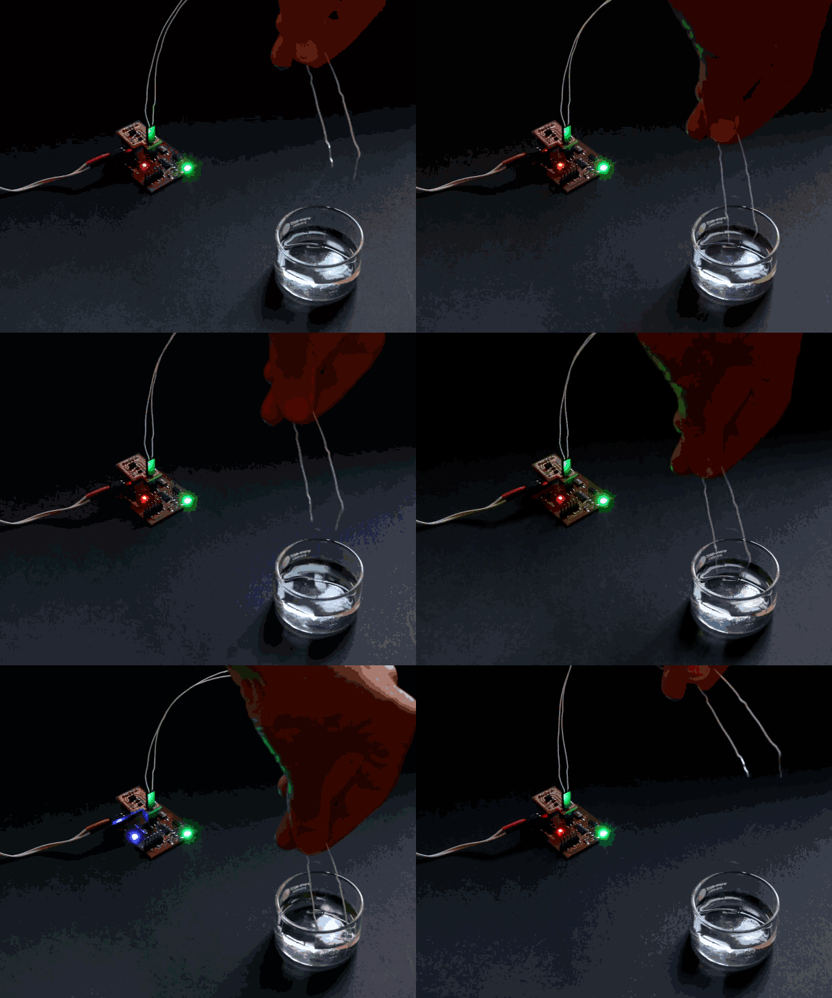
It will also output a signal on PA6 to turn on a relay (to activate the water pump) when there is water at the sensor level.