Introduction
It is the first time I make a laser cut on my own. Generally, it is a service that I pay for, however now I am the maker.
Similarly, I had never heard of vinyl cutting before, but here we go. This time, as part of the assessment,
there is a group and an individual part. I realized that the group part, which is about laser cutting, is
important because is the start point of the individual part. From the group activity, the cutting parameters
and the measurement of the kerf will be found depending on the material which will be cut. These data are
important to make the cut of the press-fit construction kit.
Group Assignment
Laser cutting
Parametric design
For the parametric design in Fusion 360, I was guided by this .
The following are the steps I followed to make my parametric design.
Step 1
Sketch
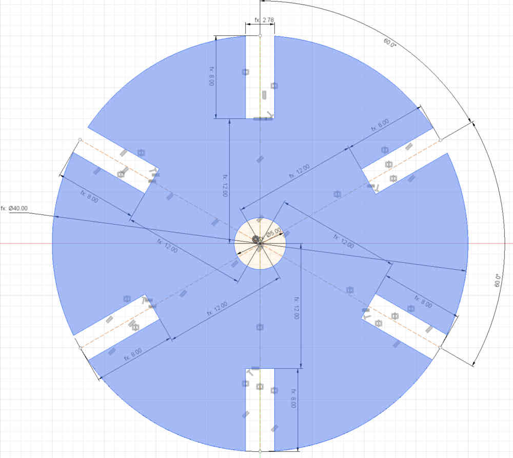
I started doing a one-piece sketch in Fusion 360 for the press fit construction kit.
Step 2
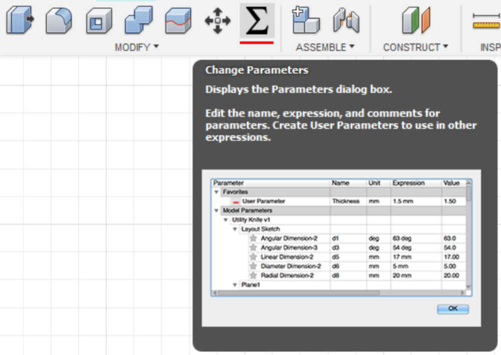
Change parameters
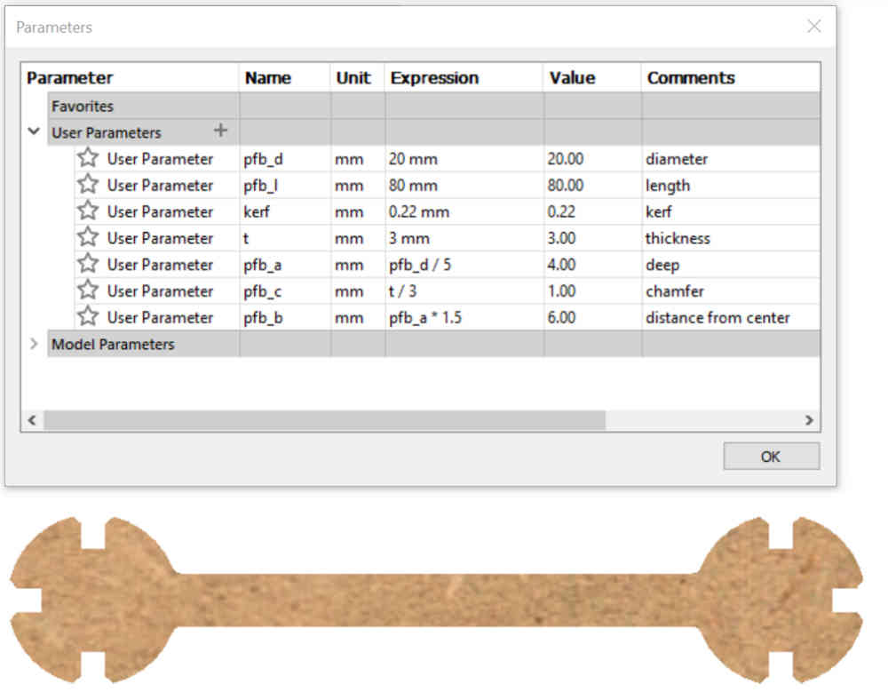
In the MODIFY menu, there is an option called Change Parameters. That is where we will put parametric values.
Step 3
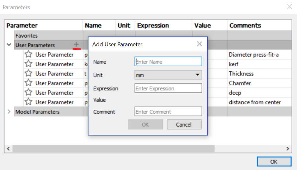
Add user parameters
When adding user parameters a dialog box appears in which you have to put the name of the parameter, the units, the value, and a comment.
Step 4
Sketch
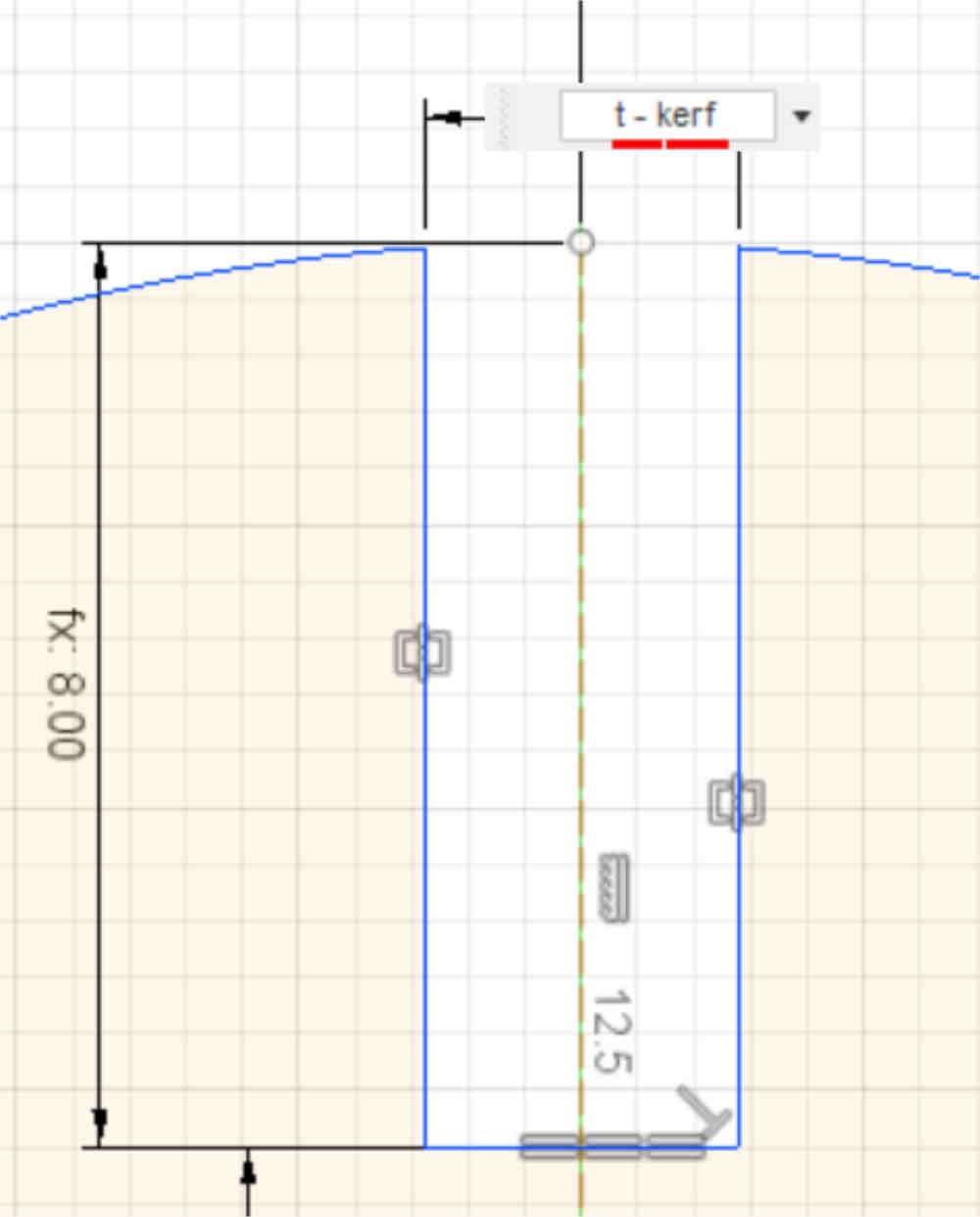
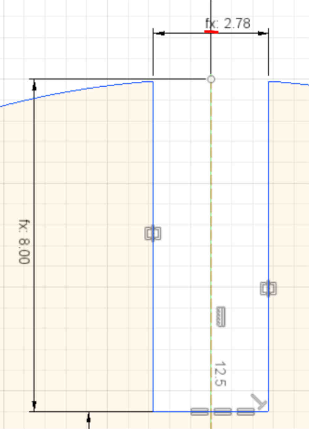
Back in the sketch, when dimensioning the distances, angles and so on, you can put the name of the parametric values.
Step 5
Sketch
After dimensioning, you will notice that it is parameterized because an fx: will appear next to the numerical value.
Step 6
Solid
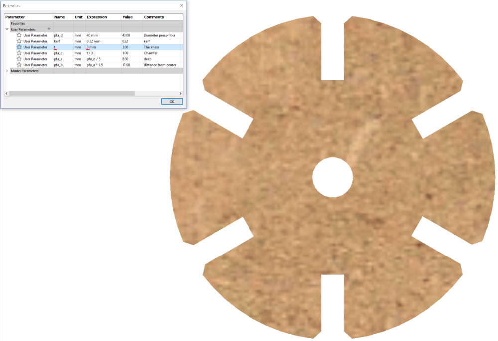
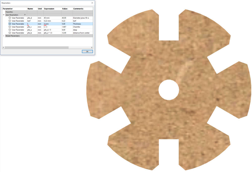
When the solid is extruded, you can go back to the change parameters option and change the values there.
Step 7
Solid
I varied the value of the thickness of the piece and it is observed that the solid changes.
Step 8
Second piece
Following the previous steps, design the second piece.
Lasercut
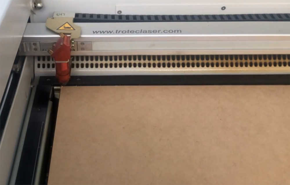
The laser cutter in Fab Lab TECSUP is a Trotec Speedy 400. To operate this machine the following steps are followed.
Step 1
Checking
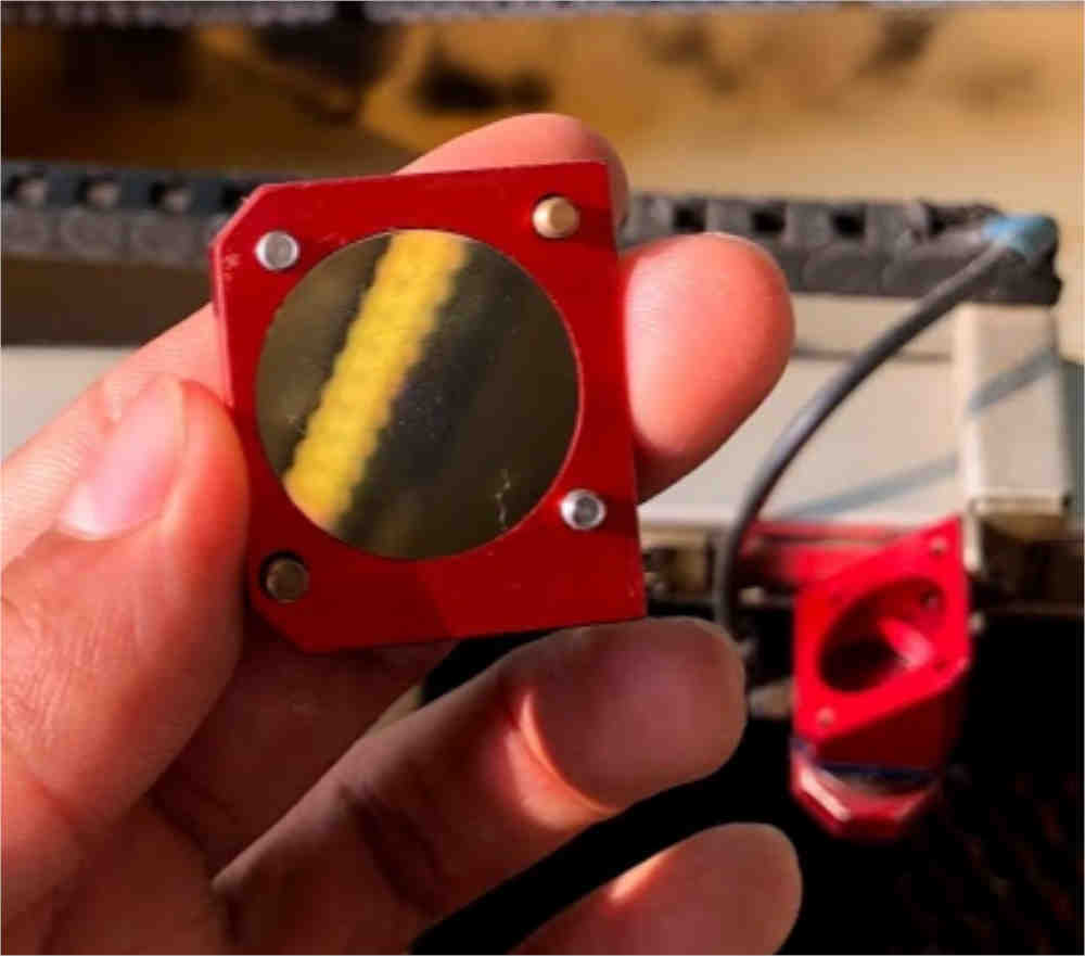
The condition of the mirror of the laser cutter must be checked. It has to be clean.
Step 2
Checking
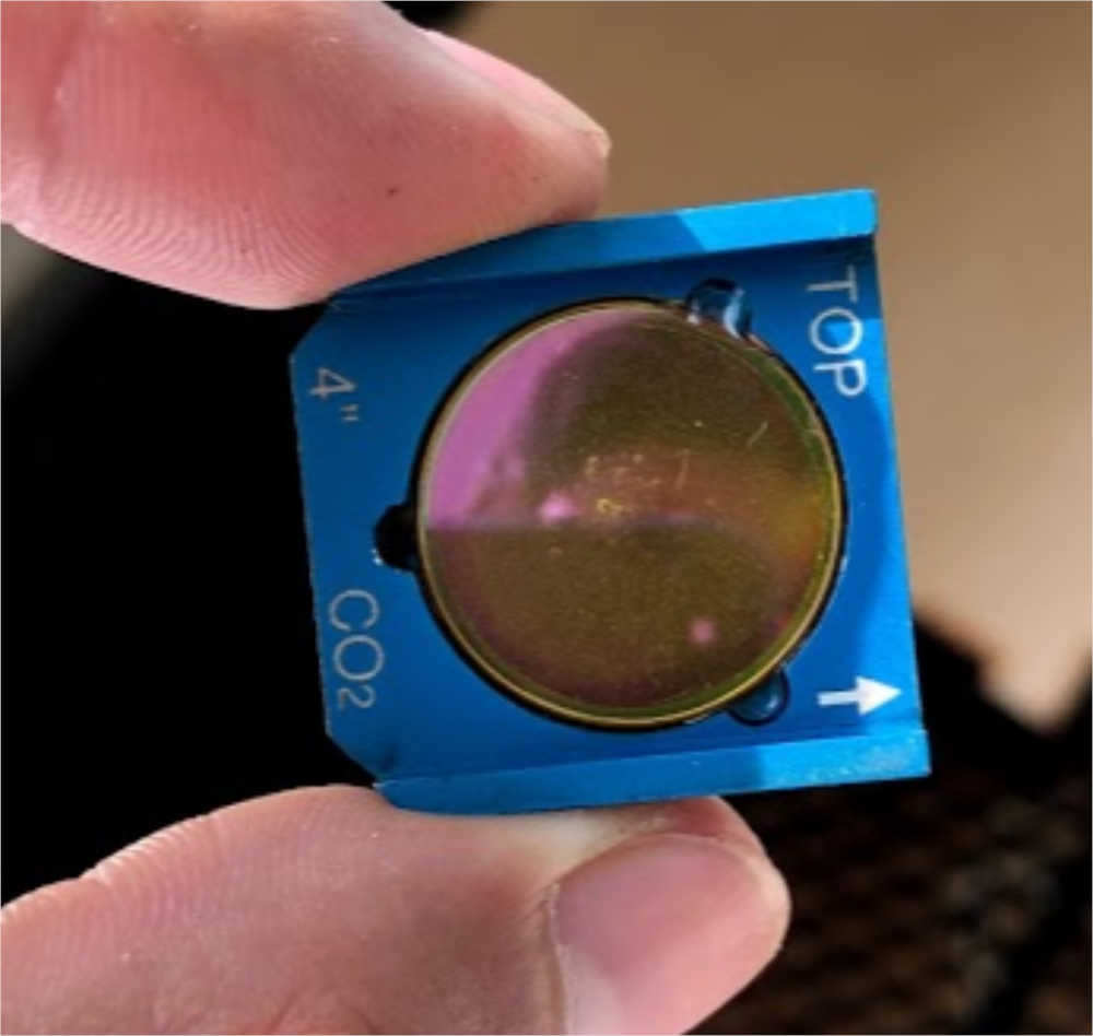
Similarly, the status of the focal lens should be checked. The cleanliness of the mirror and the lens affect the laser cut.
Step 3
Material placement
The material is placed. It must have the necessary measures to fit into the machine.
Step 4
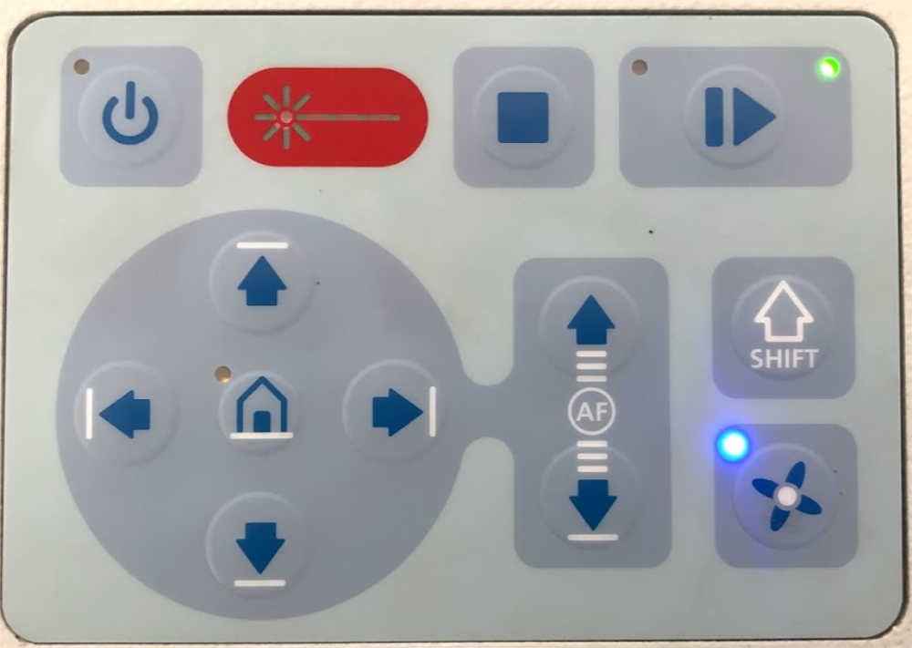
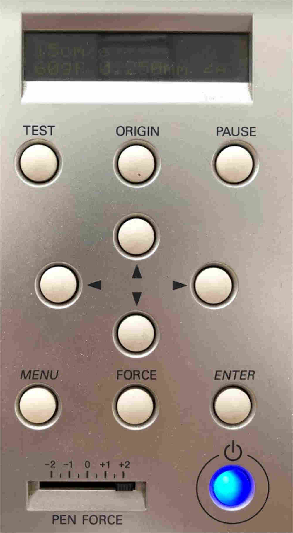
Movement
The displacement on the x-axis and y-axis corresponds to the laser cutter head and the movement on the z-axis
corresponds to the platform where the material is positioned. The image shows the buttons to control the machine.
Step 5
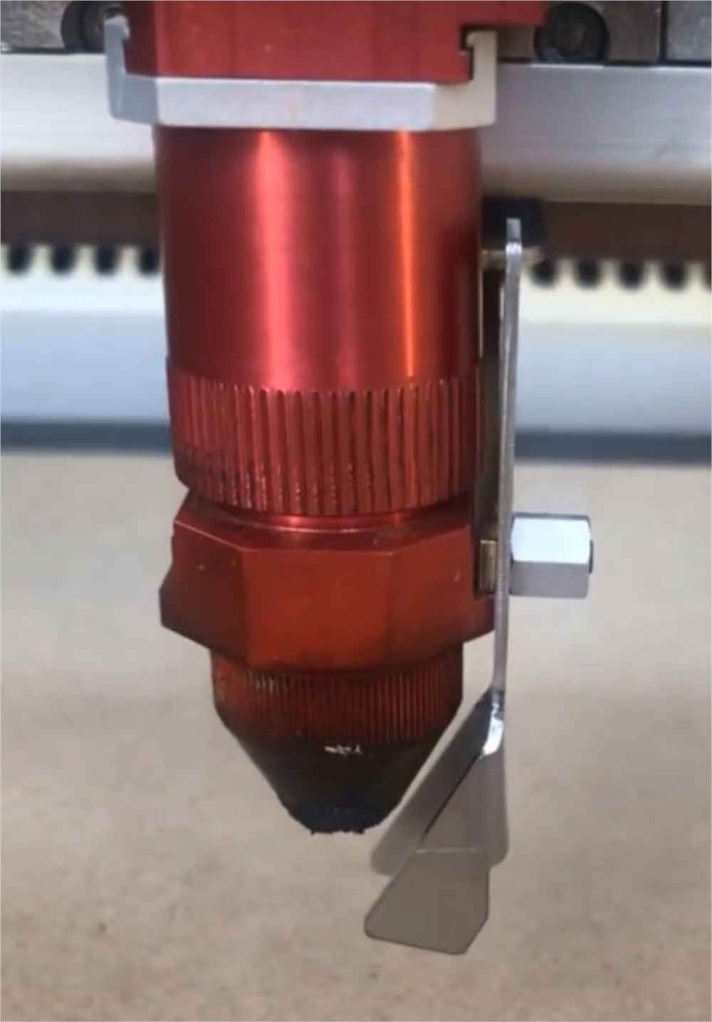
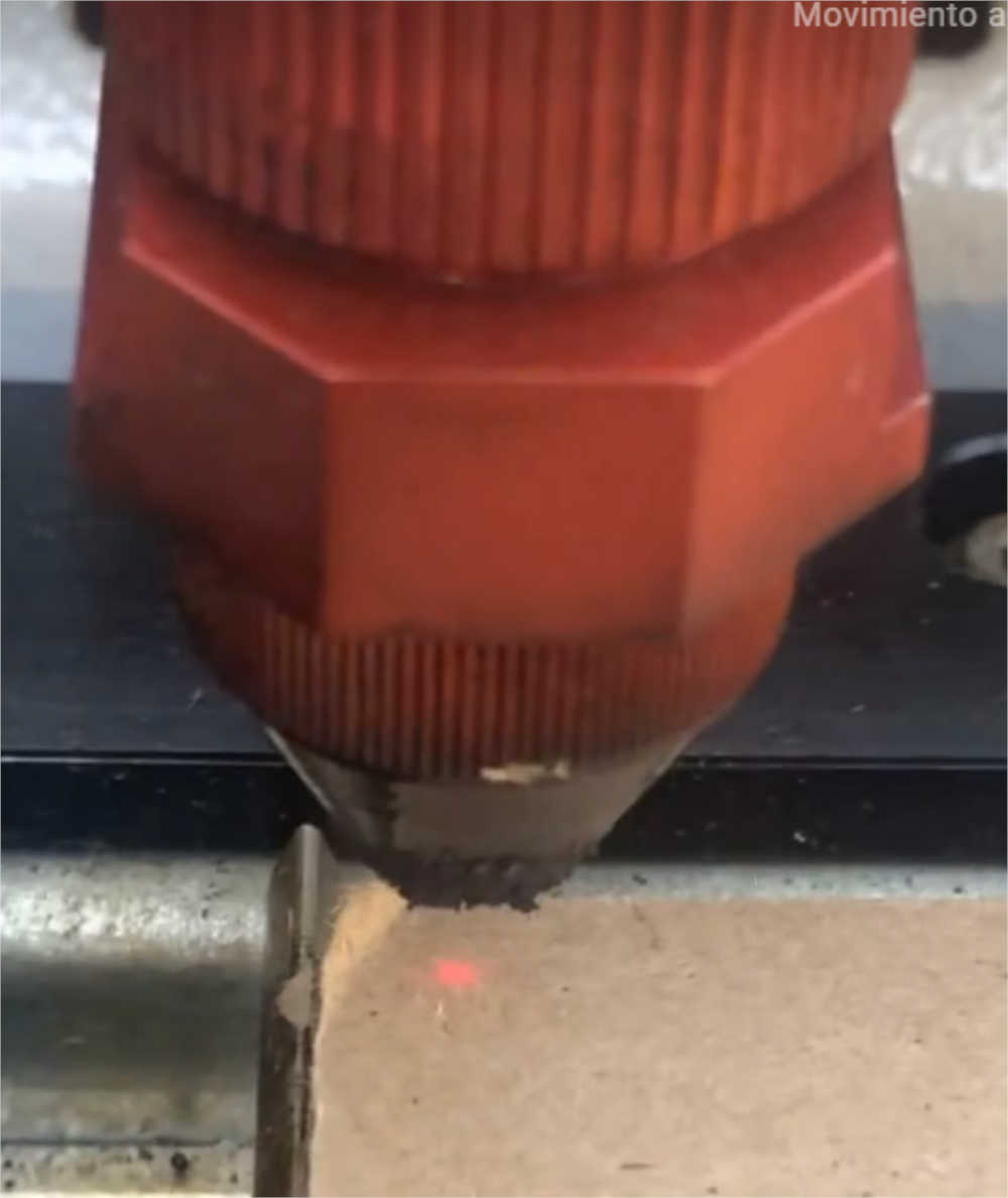
z axis calibration
The z-axis must be calibrated. For this, there is a stand that must be supported on the laser cutter head of the machine. Then move the platform with the material until the stand falls.
Step 6
Positioning
The head of the laser cutter is positioned where you want to start cutting the piece.
Step 7
Software
I exported the Fusion 360 file in a .dxf format to be able to edit it in
CorelDraw with the parameters that the laser cut needs.
Step 8
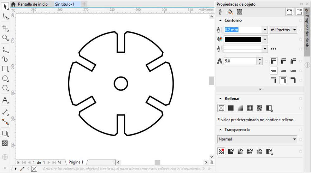
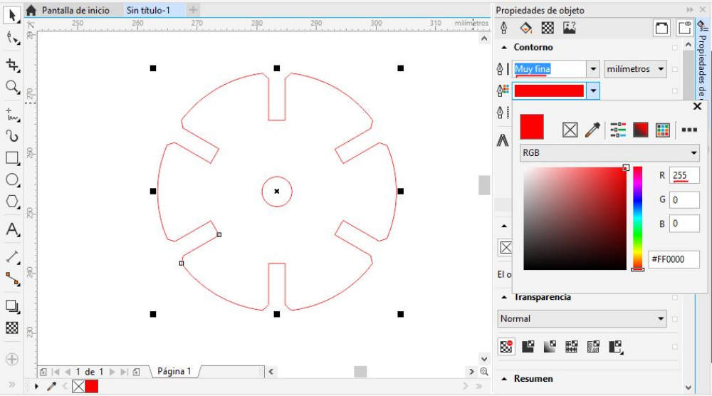
Editing
According to the cut parameters established in the JobControl® software, the thickness of the line (very thin) and the RGB color (red 255 0 0) are edited.
Step 9
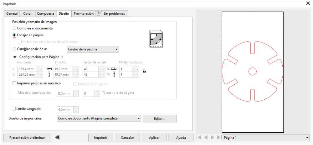
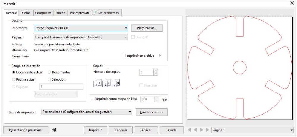
Printing
Once the properties of the object have been edited, we proceed to print (ctrl + p). In the dialog box on the Design tab, the option to fit on a page is selected.
Step 10
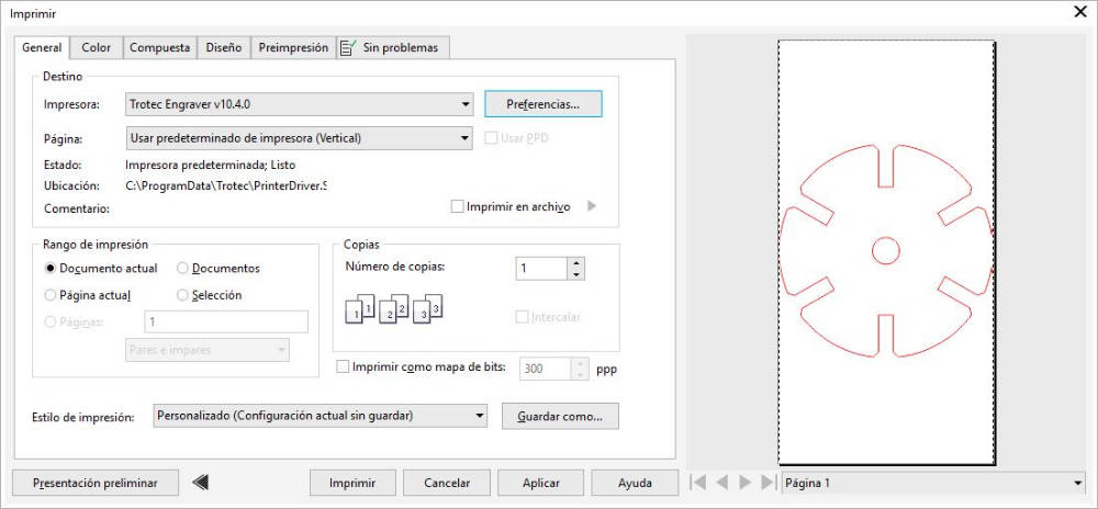
Printing
In the General tab, verify that the selected printer is Trotec Engraver.
Step 11
Printing
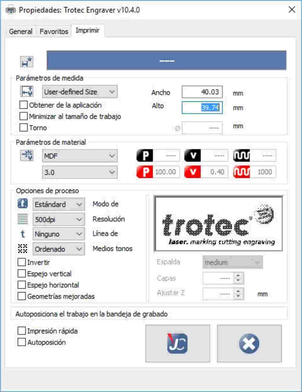
It is necessary to take into account the dimensions of the object in order to put them in the printing preferences of the Trotec Engraver.
Step 12
Printing
When selecting the printer Preferences, the following dialog box will appear. In it, we have to put the dimensions of the object and select the characteristics of the material to be cut (MDF 3 mm).
Step 13
Checking
Before printing the file, it is necessary to verify that the piece fits on the page.
Step 14
JobControl®
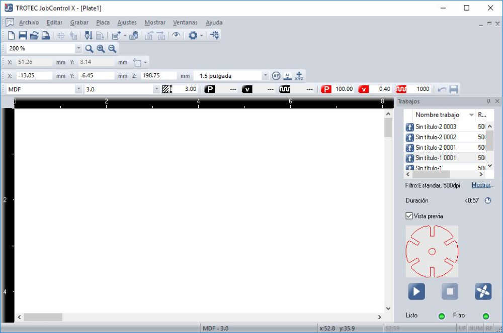
When the file is sent to print, it is sent to the JobControl® software.
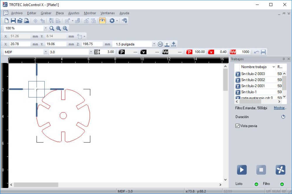
Step 15
JobControl®
The file is pulled to where you want to cut it. The pointer in the software matches the physical position of the laser cutter head.
Step 16
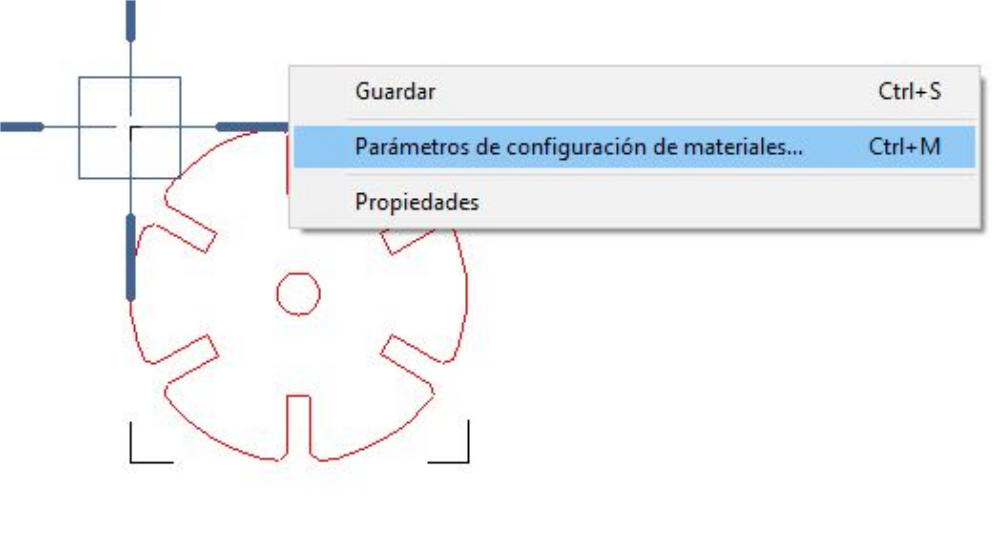
Parameters
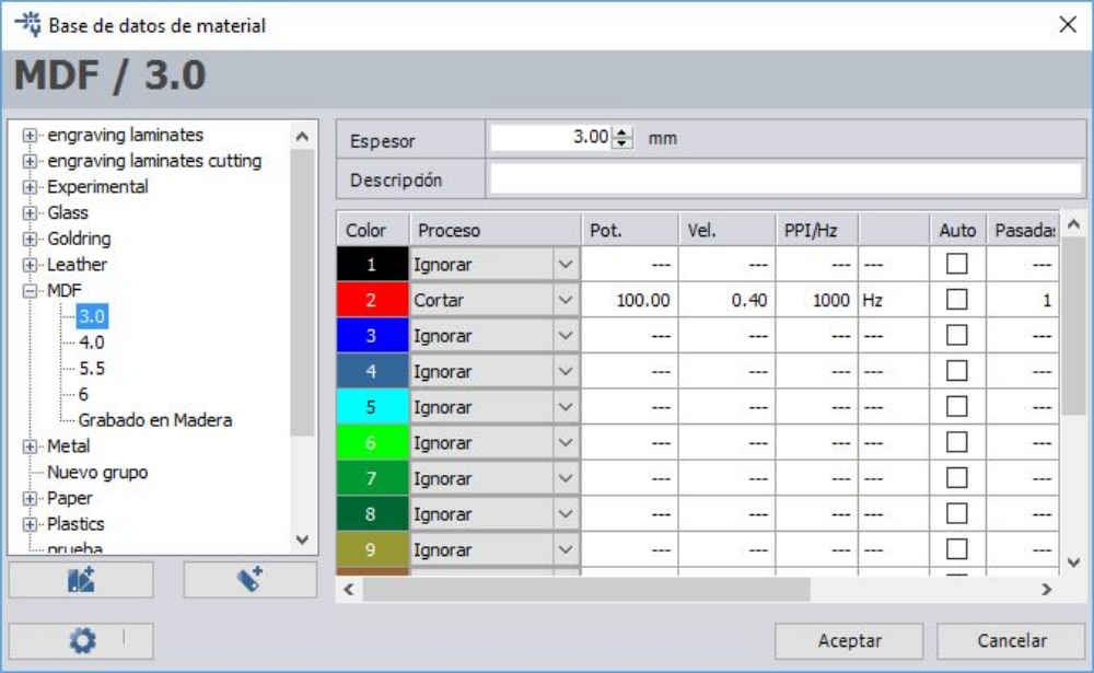
Before starting the laser cut, the cutting parameters must be verified. Right-click and select the option of Material configuration parameters.
Step 17
Parameters
The material and the parameters of power, speed and frequency are verified. In the same way, the color and the process.
Step 18
Cut
Finally, click on the play button.
Step 19
Press-fit kit
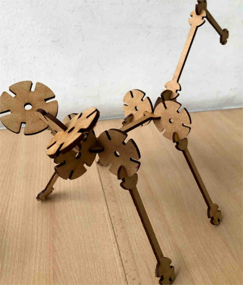
The pieces that I cut can be joined in different ways. In this case, I tried to make a puppy.
