Computer-Aided Design
- Individual assignment: Plan and sketch a potential final project.
CAD Design
For this week I want to 3D Print a card holder for my TCG cards. I will be using Autodesk Fusion 360 and Affinity Designer (vector designer) for 3D modeling and logo designing, and 3D print with a Zortrax M200 printer.
Also I will be 3d modeling my final project concept.
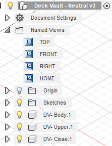
3D Design
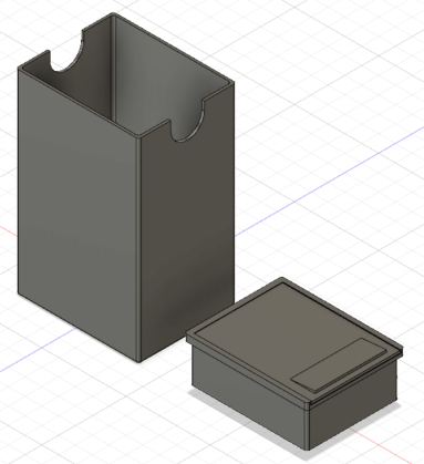
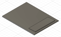
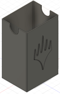
My "Deck Vault" will have 3 components: the body (largest part), top vault and top. The body will held my deck and the top vault will be used to put dices or any other game utility. Using Fusion I create 3 componentes, turning my part file into an assembly.
First I will design the body. Similar to Inventor, Fusion 360 starts with a sketch  .
Using the rectangular tool
.
Using the rectangular tool  on Fusion I drew a "center rectangle",
a rectangle with 2 points: the center and the diagonal.
on Fusion I drew a "center rectangle",
a rectangle with 2 points: the center and the diagonal.
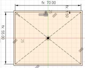
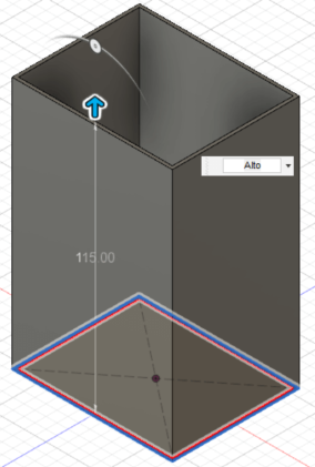
Dimensions for this part will be: 70 mm wide, 55 mm large and 1.5 mm width for wall (3d printer minimal requirement). Extrusion will give the design 115 mm height.
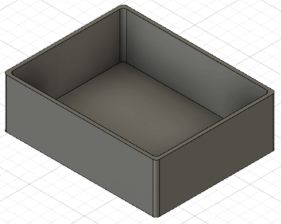
With base part completed, sharp edges will be smoothed with a 1.5 mm fillet on inner and outter edges.
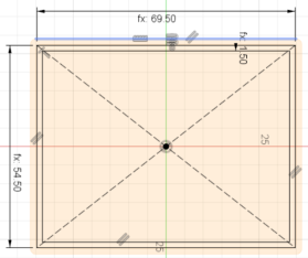
Second piece is the top compartment (upper). Same procedure as body: Rectangle tool on sketch (dimension will be 54.5x69.5mm and 1.5 width wall) and extrusion for basic form (21mm height and additional 1.5 mm for base). Same fillet radius for sharp edges.
The "crown" feature (serving as hard stop and avoiding the upper component to fall), is added on the top face of the component. This part will have a gap for top insertion. To avoid problems with haging parts, I will be using a triangular shape which is deducted from the front face (using extrude operation as cut).
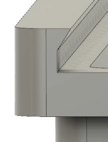
Finally the top will be rectangular with a triangular feature for easy open. Picture on left shows how looks.
2D Design
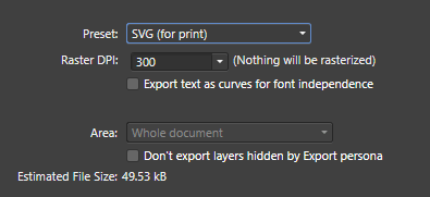
Using Affinity Designer - a vector desginer - I will add a logo to the deck vault. Fusion uses SVG *Scalable Vector Graphics) format, so I will need to export my file into that format.
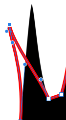
Using an image as a base, I use the pen tool  to create the vector image.
The pen tool allows to draw a line and then modify it freely.
With that, I can draw the contour for extrusion on Fusion.
to create the vector image.
The pen tool allows to draw a line and then modify it freely.
With that, I can draw the contour for extrusion on Fusion.

Once the contour is finished, Affinity allows to export to SVG directly.
Once exported, I return to Fusion o insert it on my 3D.
Once again in Fusion, I create a sketch, add the image, rescale it. Thanks to the SVG format, the file will scale nicely without losing resolution.
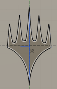
Once the image is well placed, the extrusion is made. To make the extrusion better fit for 3D Print, an small fillet (0.8mm) is used. Now the the solid is ready for 3D print on next assingment.
Project Modeling
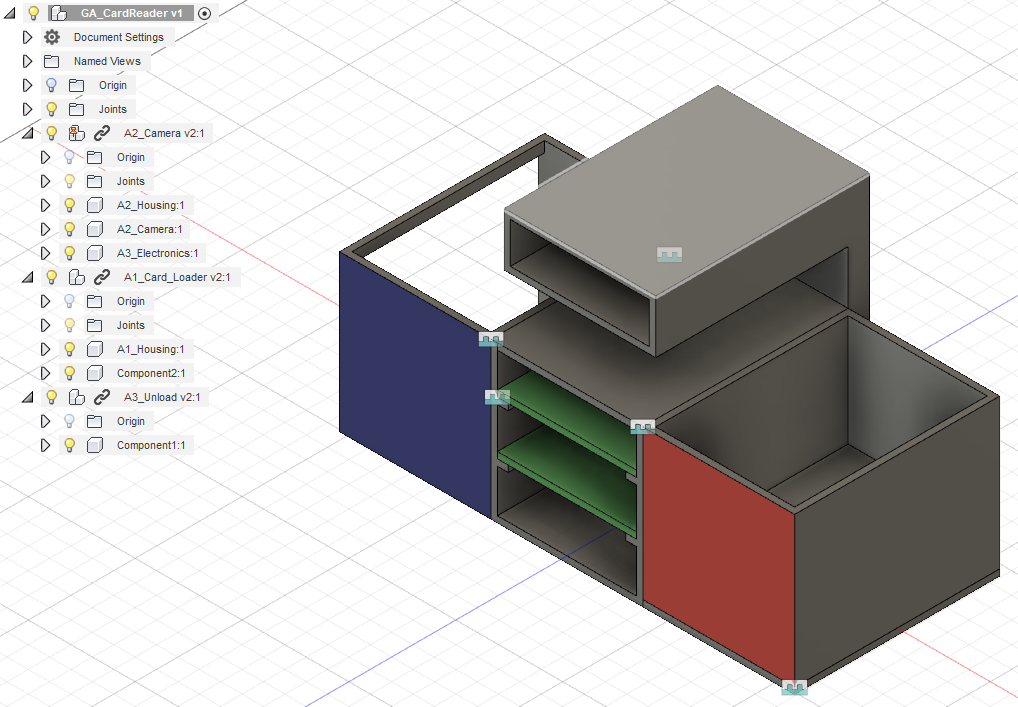
Using Fusion 360 I modeled my Card Reader. It is a 3 part assambly with a load bay, where cards rest before getting scan; a central bay where a hanging camera will get card name; and a unload bay, which will hold all cards already checked. Each component is modeled on a separeted file and join together on a general assembly file (GA_CardReader on the image below).
For this modeling, general considerations where taken:
- General card dimension was set as 65x90 mm (real card dimension are 63x88 mm).
- All "walls" should be 3 mm to consider 3mm MDF material when laser cutting.
When operating, the cards should move from the load bay(red face component) to the camera (component with 2 green cards representing electronics). The mechanical system to card movement between modules is not clear, thats why are not modeled yet. Finally the cards are moved again to the final repository (blue face component).
One of the main problems to take care in this project is the mechanical aparatus to make cards move. The load bay first issue is to make cards available on top to move to the next area. A spring is my first idea with servos connected to a Arduino board (or FABduino) as operators.