3. Computer Aided Design
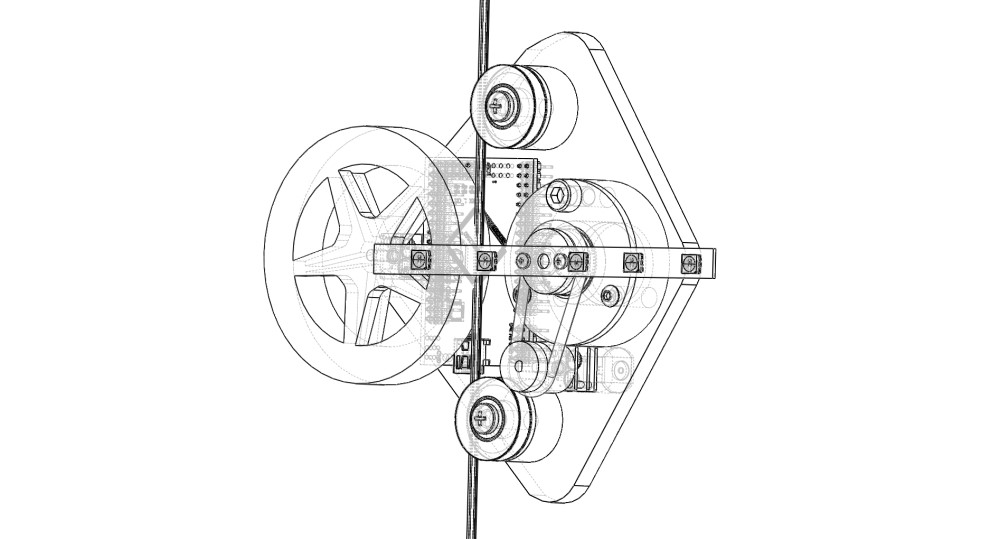
This week started using the 3D software SOLIDWORKS to build a virtual model of a robot to visualize the data from a water level sensor. The model has a bunch of parts and I’m going to start with a critical part of the robot. My goal is to pass power through a v-groove bearing so I’m going to start with the bearing. Then I’m model the rest and assemble the robot virtually.
Files
3D Files
Short Bearing Hub (SOLIDWORKS) (.STL) | Frame (SOLIDWORKS) (.STL) | Large Wheel (SOLIDWORKS) (.STL) | DC Motor (SOLIDWORKS) (STL) | Small Belt Pulley (SOLIDWORKS) (.STL) | V Groove Bearing (SOLIDWORKS) (.STL)
2D Files
Prototype Frame for Laser (CorelDRAW) (.DXF)
Evaluating Software
I looked at the software listed below and decided my prefered workflow is going to be Solidworks for 3D, Corel Draw for 2D vector for the laser cutter and Vcarve for 2D for the Shopbot.
3D
SOLIDWORKS for the Win
- works locally
- Only works on PC
- exports to STL adn OBJ
- Can import 2D vector
- Has a great material library
TinkerCAD
- Works online
- Has a size limit
- Is great for Kids
- Difficult to build relationships between objects
Xdesign
- feels like SOLIDWORKS
- Works online
- Works with Mac & PC
- My computers browser and internet doesn’t seem to support it
2D
Corel Draw for the Win
- Has the Epilog driver for seemless laser cutting
- can input measurements
- Joining shapes is easy
- Fab Lab Houston has free license to use
- Hairline is an easy line thickness to remember for vector cutting on the laser
- Doesn’t work with the Shopbot (have t export to v-carve)
V-Carve
- Easy to navigate
- Seems to be designed for shopbot not so much laser
- CAM setting match ShopBot
- Can be used to design files for the Laser Cutter but files have to be exported to Corel Draw.
Illustartor - really expensive - Has to be exported to Corel to use with Fab Lab Houston’s Laser Cutter
Exploring CorelDRAW
CorelDRAW feel alot like Microsoft Paint. At first it was a bit of a turn off but after using it the deatures you need are easy to find.
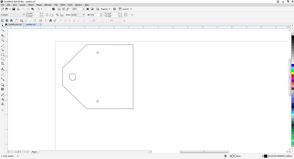
I make the canvas size the same size as the laser cutter’s bed 24” x12”. This setting is at the top. On the left is a toolbar that has all the essential vector drawing tools. To draw this shape to hold the motor and bearings I used three rectangles, rotated two of the rectangles then subtracted to two rectangles to leave the irregular shape.
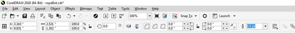
When a tool is selected the second toolbar at the top changes to reflect all the settings for the selected tool. These are the rectangle settings. The .5 on the right side is the Stroke weight and can be changed to Hairline to cut the material with the laser.
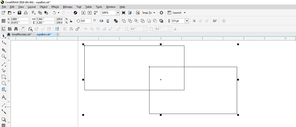
If you shift click two overlapping object the combine, subtract options will appear in the top toolbar. This is how I created the shape for the motor mount plate.
Learning SOLIDWORKS

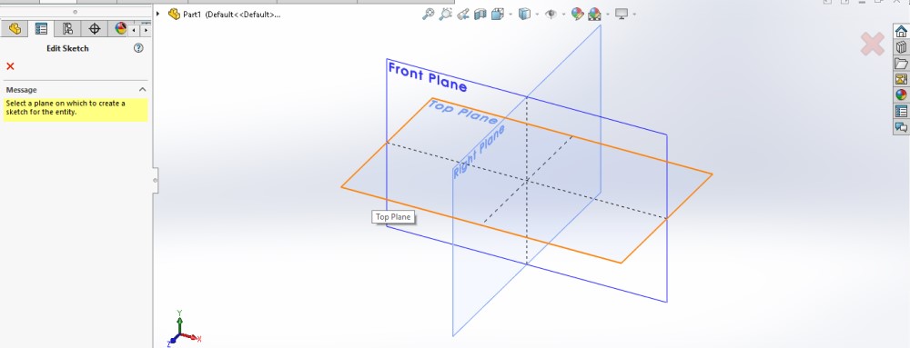
The begining point of creating a model in SOLIDWORKS is to create a new PART. Then, click SKETCH and select the plane to draw a first shape.
Drawing
SOLIDWORKS quickly felt intuative as I saw parallels to drawing with pencil on paper. Begin with the basic shape to get proportions and add more detail.
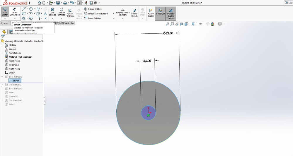
When drawing the intial shape I didn’t worry about the size. The DEMINSION tool made it easy to select and shape on my active SKETCH and define the size of the shape. The drawing can be in either mm or inch but it can’t be defined in both.
Extruding
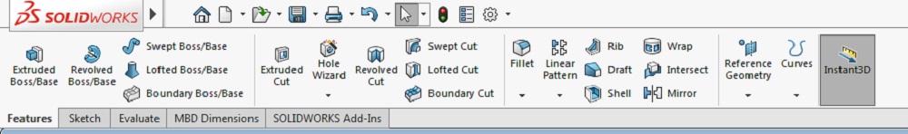
The FEATURES toolbar at the top of SOLIDWORKS allows you to select a shape on an active SKETCH to EXTRUDE and CUT.
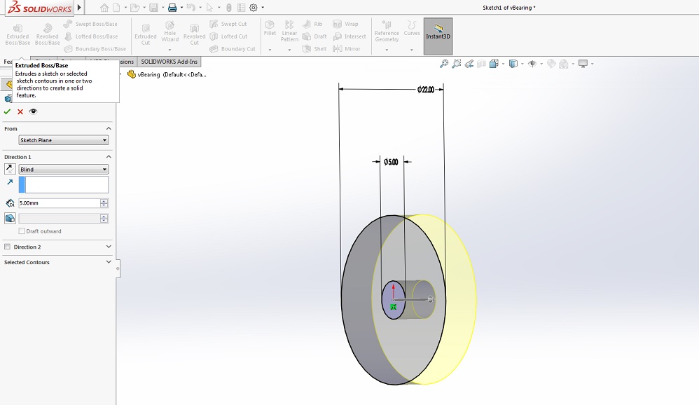
When you select a shape and click EXTRUDED BOSS/BASE the side panel allows you to select the direction of the extrusion and the deminsions of the body.
Cutting
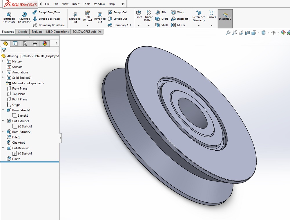
There is a groove on the top o the bearing and I used the cutting tool to add the groove to the model.
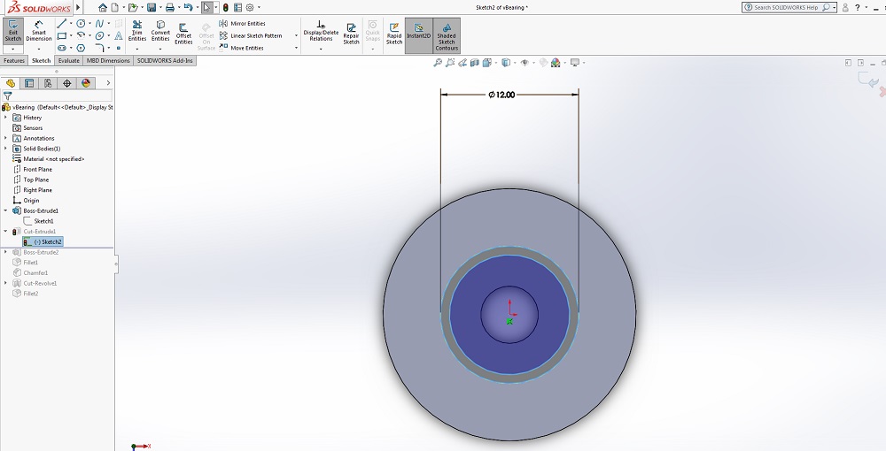
Because I want to cut into the surface of the bearing, I selected the face of the bearing as the SKETCH plane. Once the plane wa selected I created a circle on the face.
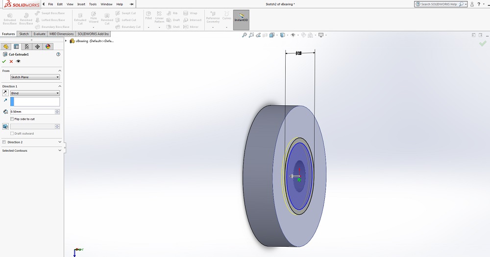
With the circle drawn and selected I used the EXTRUDED CUT tool to cut into the face .5mm.
Fillet
The FILLET tool allows you to round edges and identify the size of the fillet
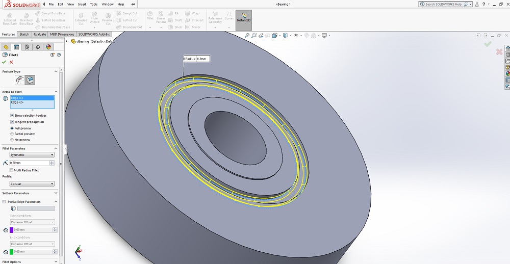
I used the FILLET tool to round the inside edge of the groove in the face of the bearing.
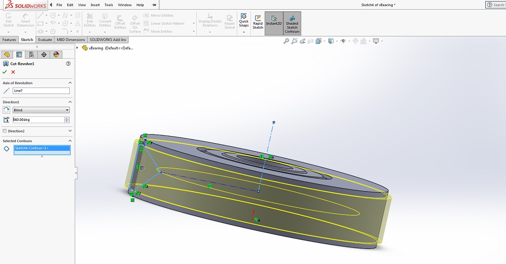
Revolved Cut
To cut the v-groove around the edge of the bearing I used the REVOLVED CUT tool.
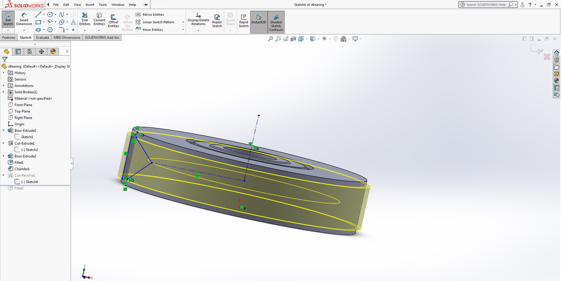
To start I had to make a new plane at the center of the bearing. On that plane, I created a verticle line to revolve around and a triangle for a contour.
Assemblies
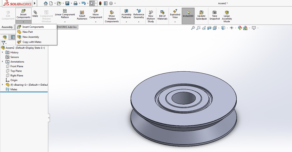
Once I designed the first two parts I started an Assembly to attach parts together a test clearences. Assemply is an option when you select new SOLIDWORKS Document.
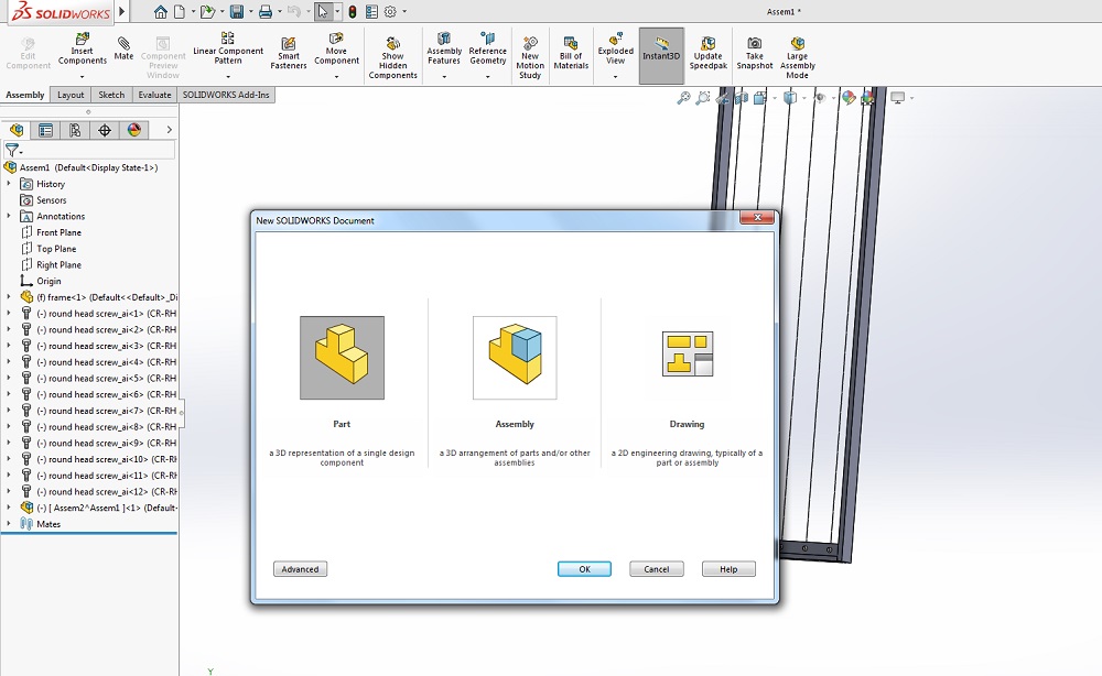
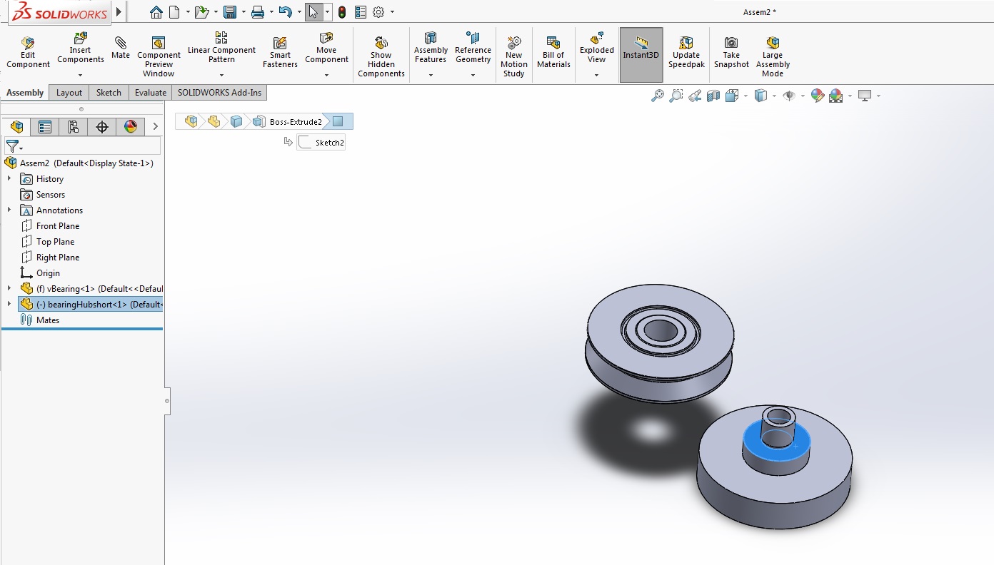
The assembly document will open and look like a blank part but in an assembly you and insert components.
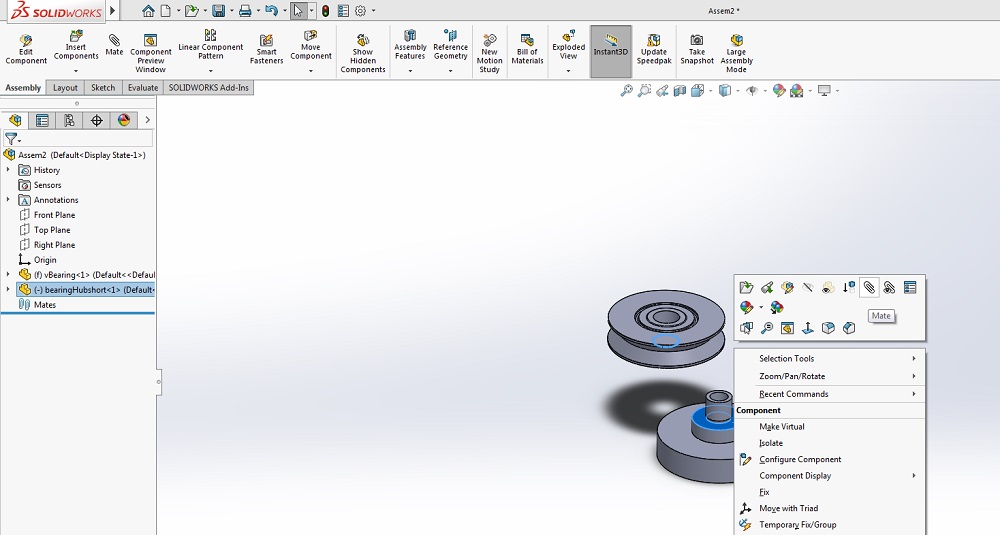
Once multiple components are inserted into the assembly parts can be aligned and mated. Start by selecting two edged or faces that touch each other at the same time by holding down shift and click on the touching area on each part.
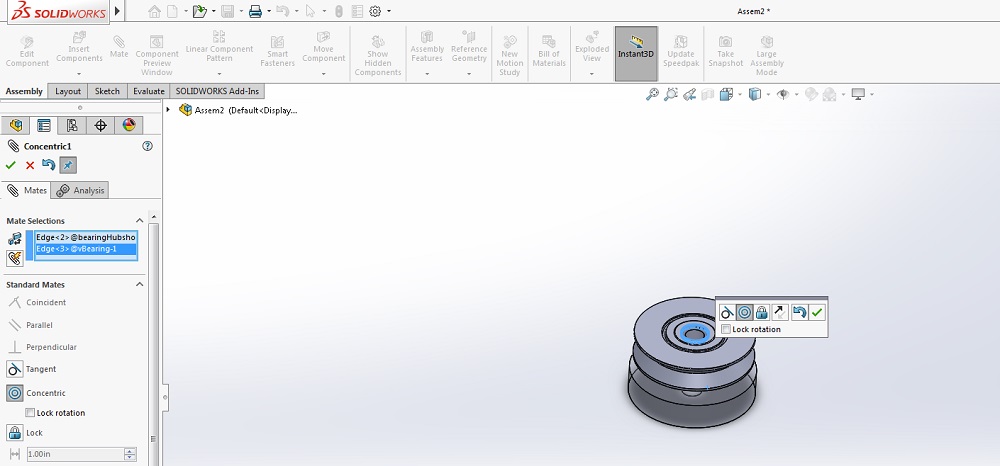
Once selected the hover menu pops up and you can click on the paperclip icon. The paperclip represents the MATE action, which moves the selected part until they touch. Objects can have multiple mates with multiple components.
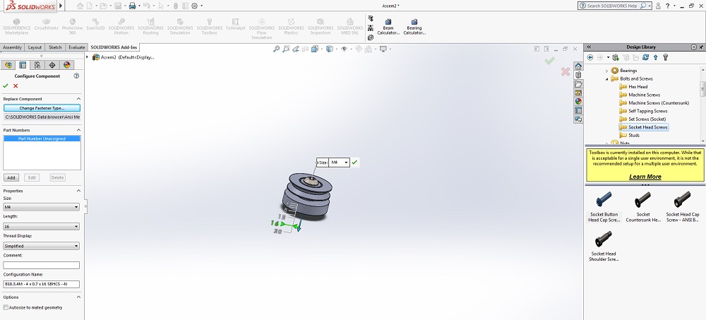
Toolbox and Screws
Another cool feature of SOLIDWORKS is the toolbox on the right side bar. It allows you to select a hole and insert a screw the size of the hole.