7. Electronics design
I have no background in Embedded Electronics designing. Neither was I able to figure out what these 1, 2, 3, 4 are. So I decided to blatantly copy the design from here (which I regret later on!)
Since I assumed I would struggle to understand the core job in hand this week, I decided to play on the safer side and stick to the closed source, but well documented Eagle from Autodesk. This week’s assignment is to make a programmable board with atleast an LED & a push button. The board should be able to make an output via the LED when we give the input via the button.
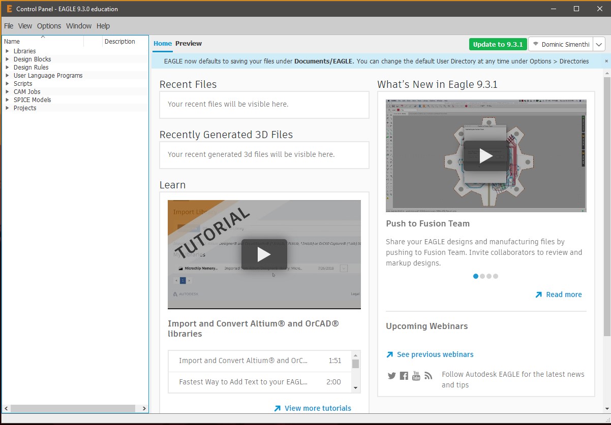 Start page for Eagle
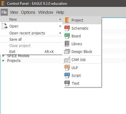
Start a new project with File > New > Project
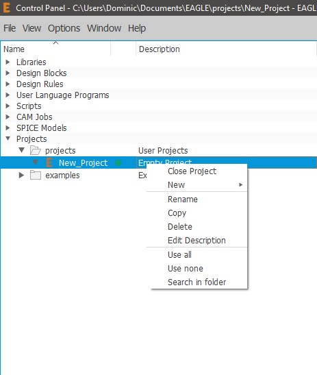
Start a new Schematic by project > double click on the project to turn on a green button > New > Schematic
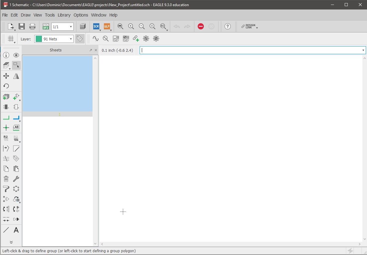 Blank page for making schematic
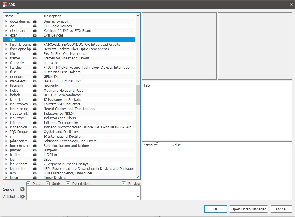
 Download fab library for eagle from git
 Add the fab library to use
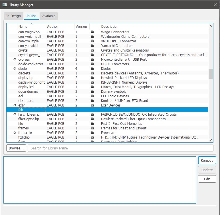 Making sure the library is added
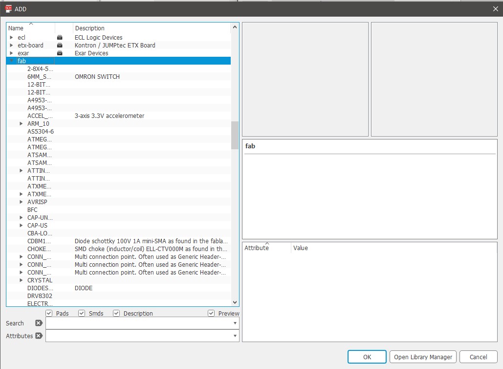 Using the fab library for adding components
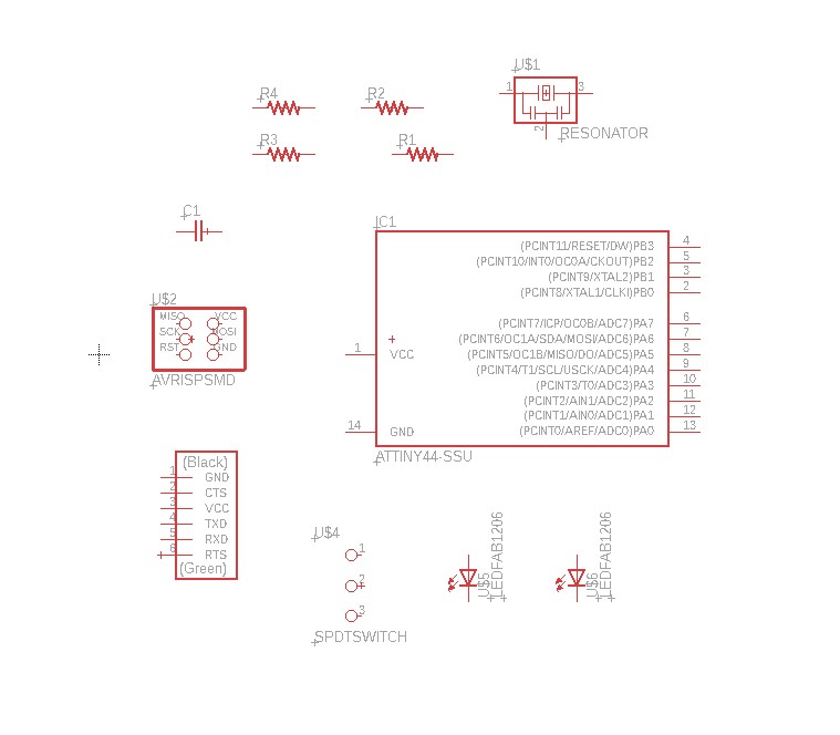 Laying out all components

Use the Net tool to add connections to the components
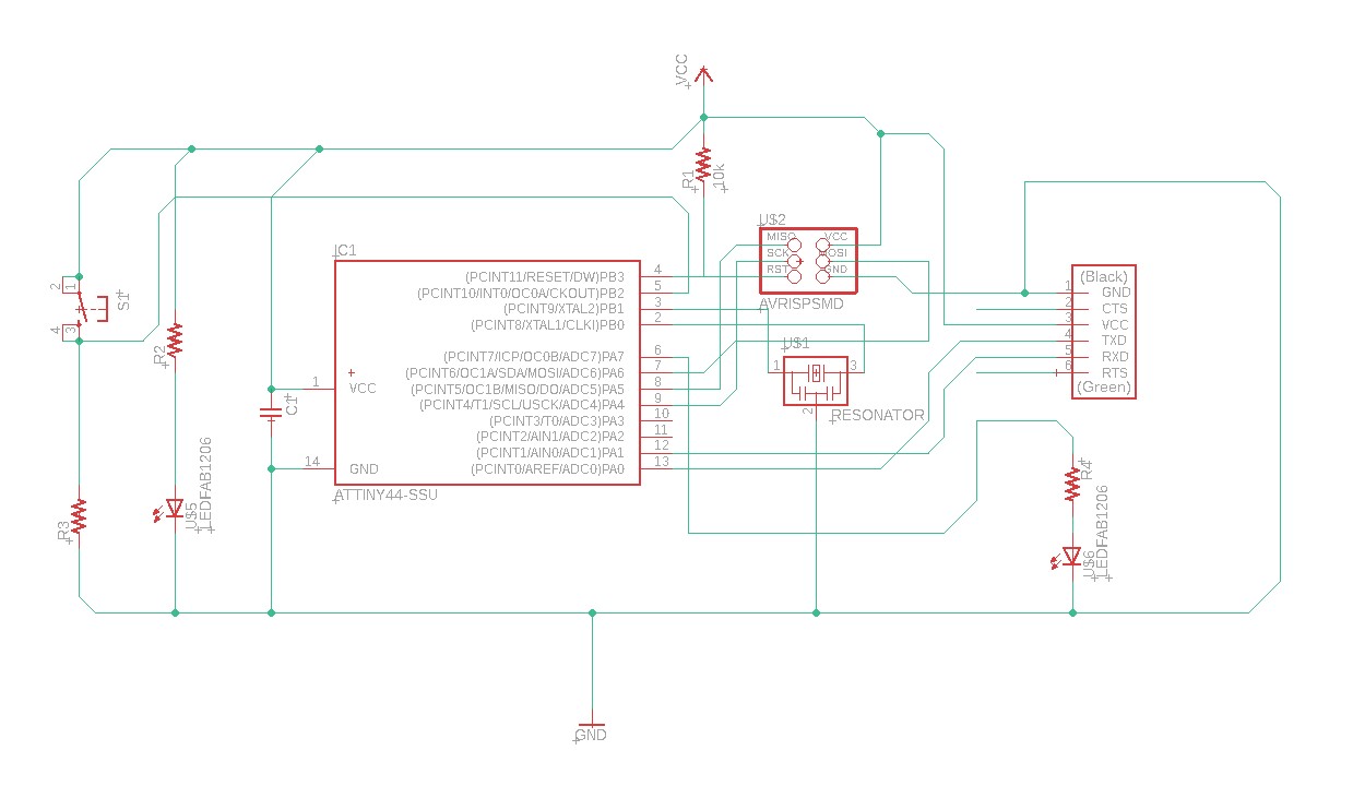 Schematic with all the components connected
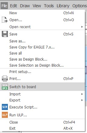
Switch to board to do routing
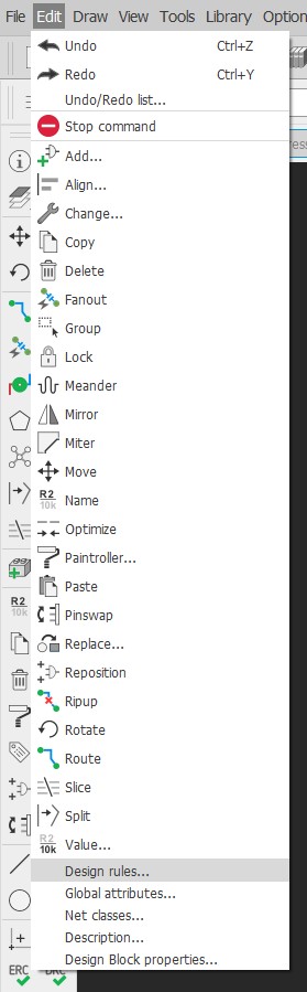 Select the design tool option by Edit > design rules
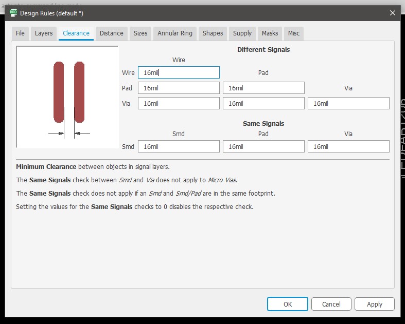 Design rules changing Clearance parameters
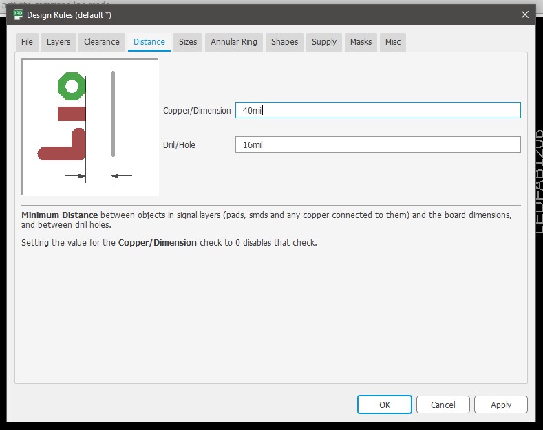 Design rules changing Distance parameters
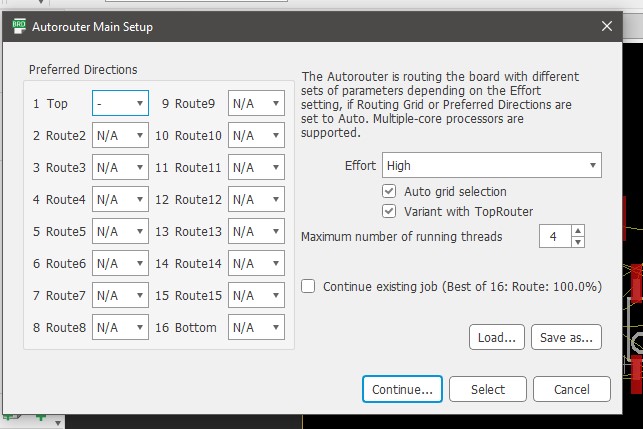 Seting up auto router Main setup
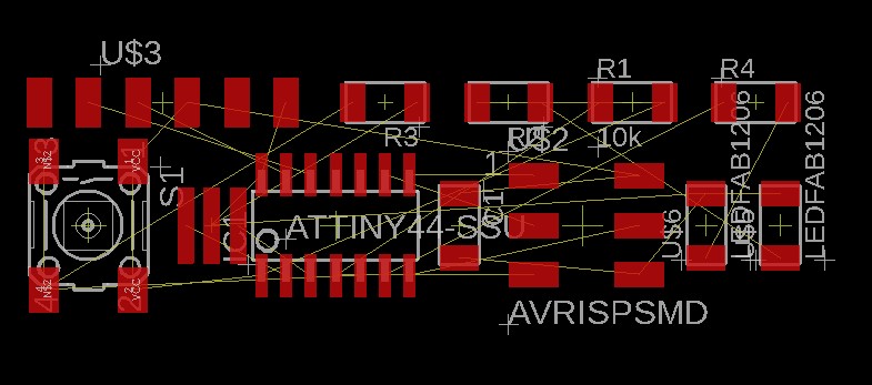 First design with missing links
 Use the ripup; command to do a reset of the autoroute
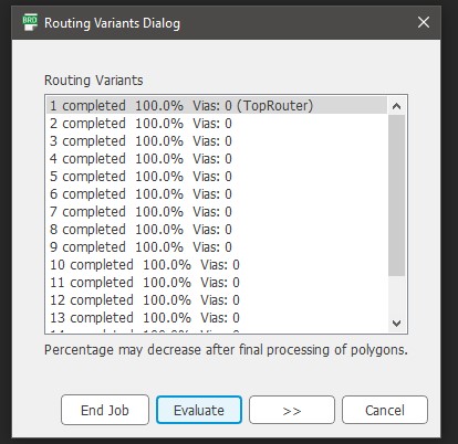
100% Connections after multiple iterations
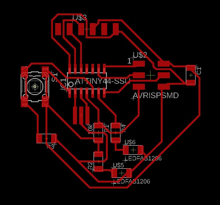
Final PCB design after routing
Now we have to do the milling & Soldering of the pcb. The approach is the same as on week5
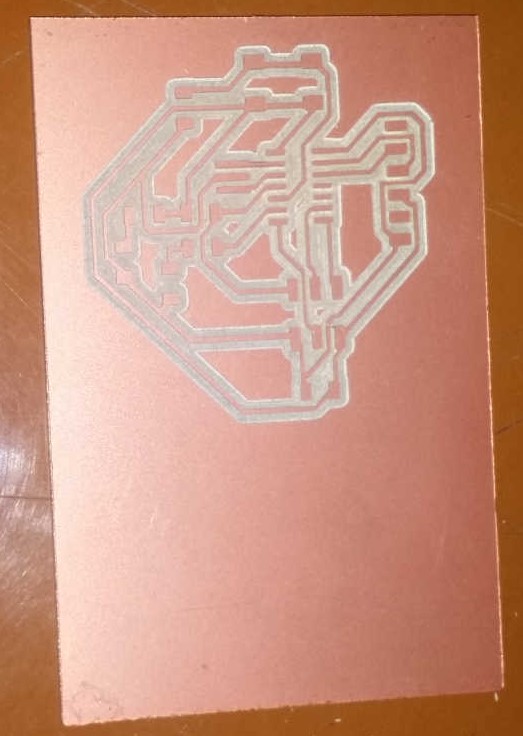
PCB after milling & cutting
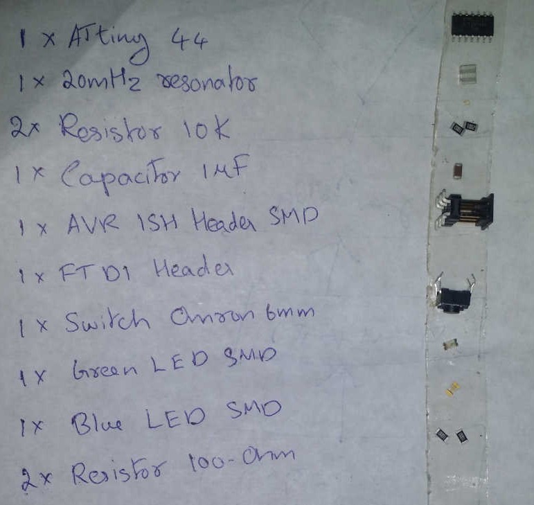
Components required
Download