4. Computer controlled cutting
This week we learned how to work with a vinyl cutter & laser cuttter
Vinyl Cutter
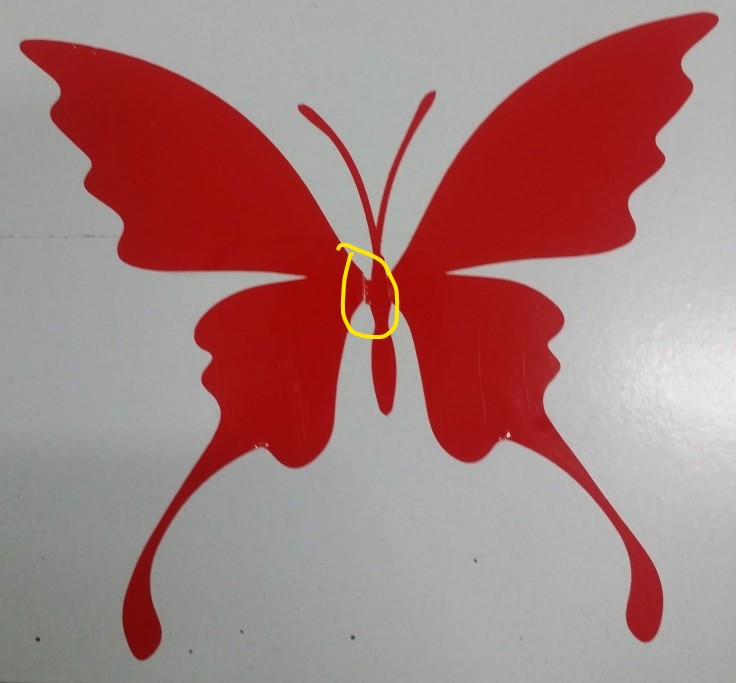
An svg format file of a butterfly was downloaded from internet & printed using the mods interface.
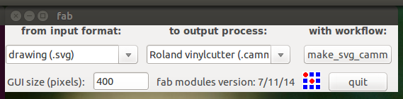
Mods UI is very straight forward. Open the app from terminal >> Select the input file type >> Select the machine >> Select the workflow
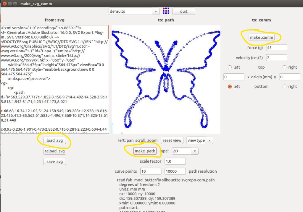
After clicking the make svg camm button, a new interface will pop up. load svg (select the svg file) >> make path >> make camm.
You can vary the force & velocity of the blade path. Always do a quick search to find the best values for the same from internet. (You could always learn the hard way by messing around with the values which is not recomended!)
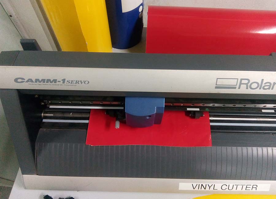
Before the actual cutting can be done, the vinyl sheet should be loaded on the machine. Hold the loading lever and put the sheet. You can use small sheetof vinyl or entire roll. The same should be selected on the machines display using the arrows and enter buttons.
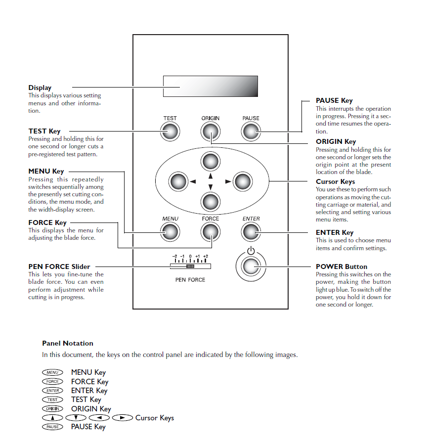
The origin also should be set using the buttons.
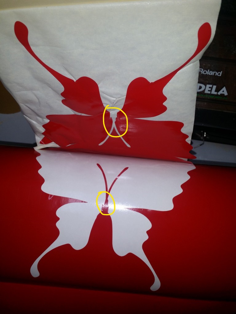
The cut vinyl is removed from the roll with the help of masking tape. See that I did a poor job at transferring the sticker to the masking tape!
The masking tape along with the vinyl is placed where it needs to be applied. After applying slight pressure, peel off the masking tape.
I believe a steady hand is extremely important for doing stickering job. Cutting the sticker is a relatively straight forward operation. Peeling off the cut sticker and applying without wrinkles is more of an art.
Laser Cutter
By this time, I became so accustomed to Autodesk Fusion 360. I used the same for this job.
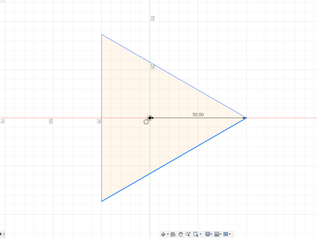
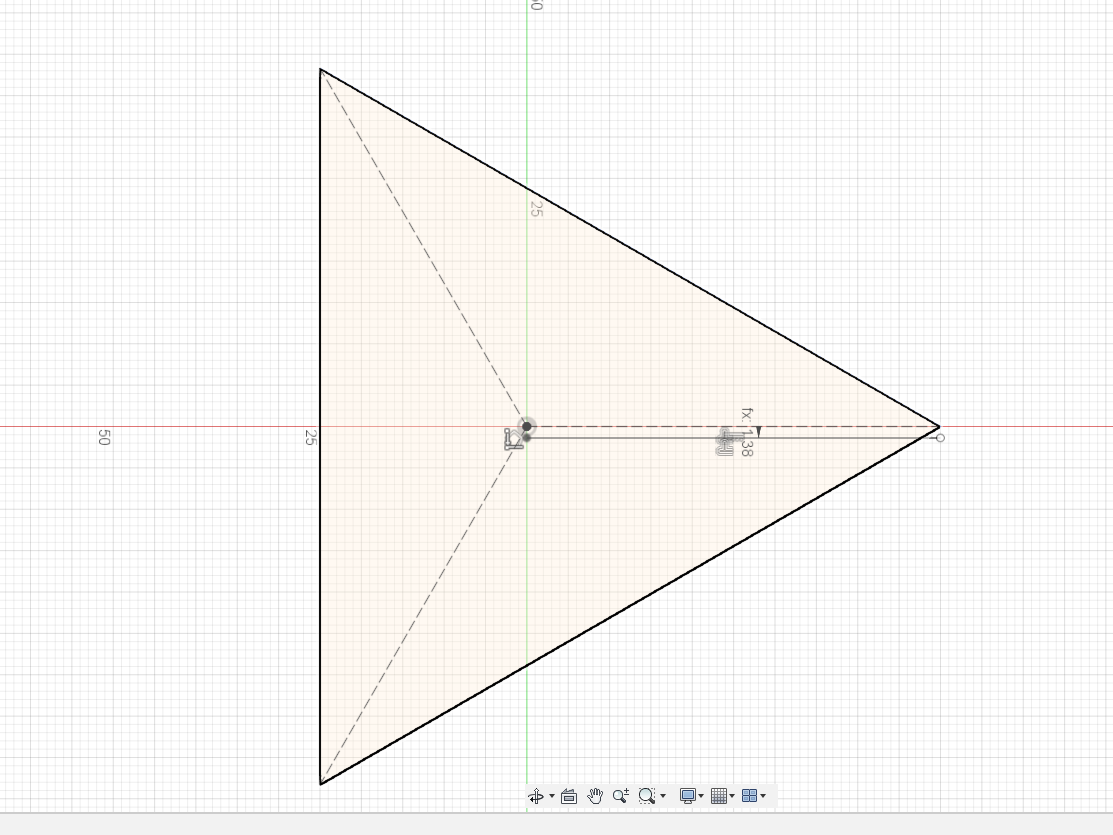
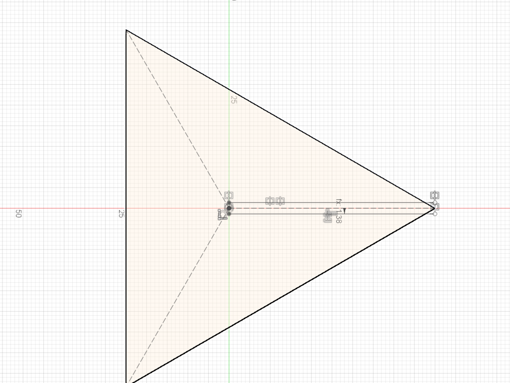
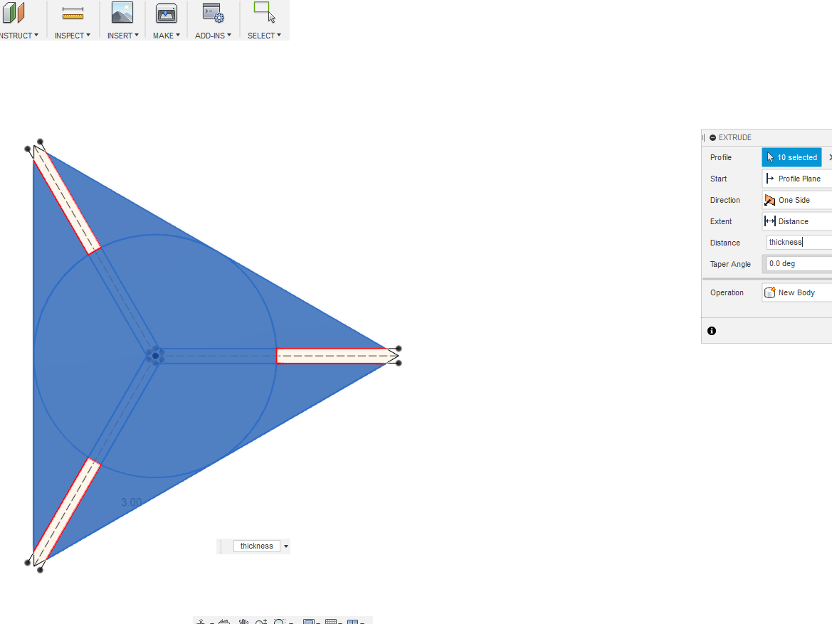
Started with a plain triangle
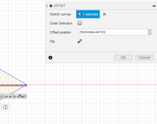
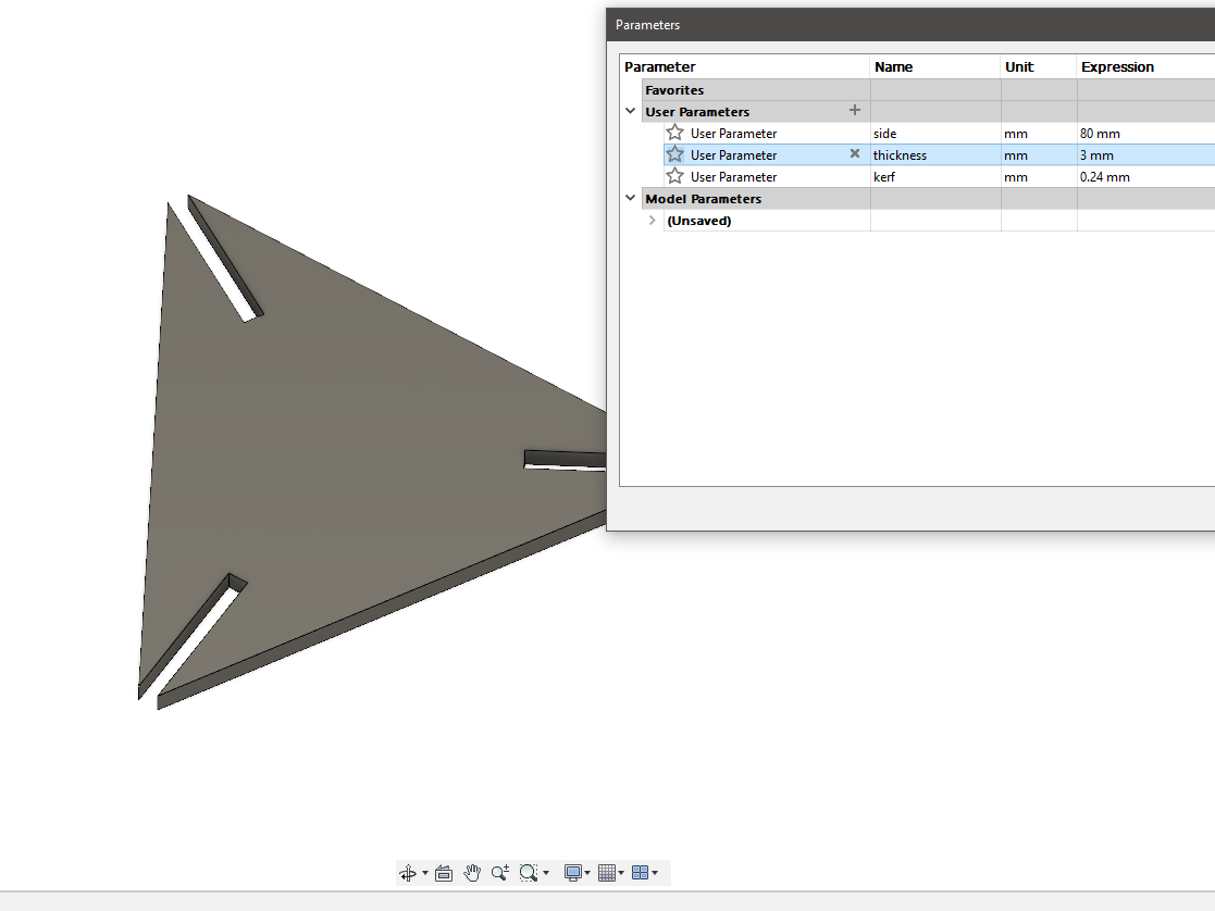
The thickness was made taking into account of the kerf. (Parametric modelling)
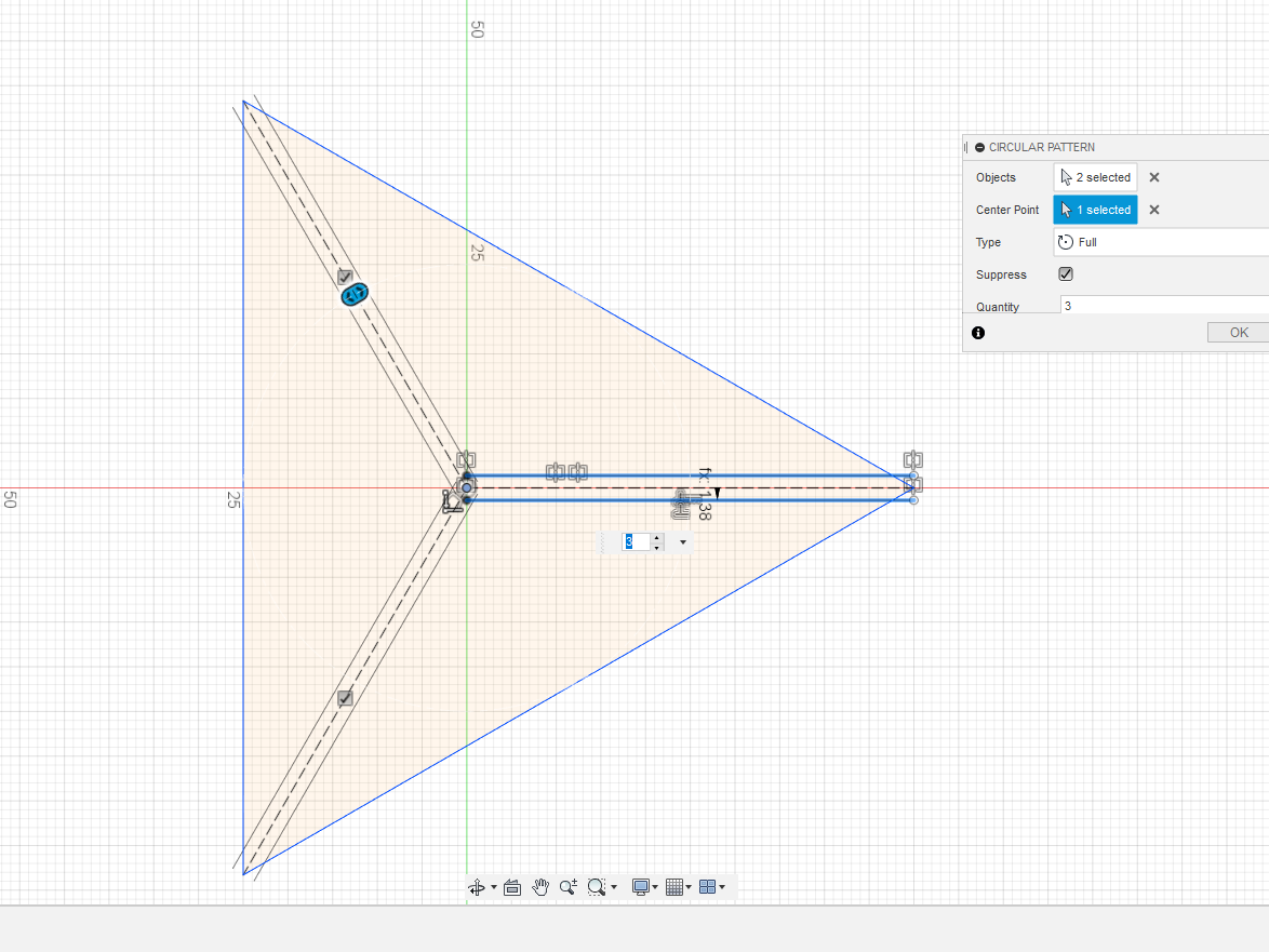 Used the circular array for putting the slots in the three corners
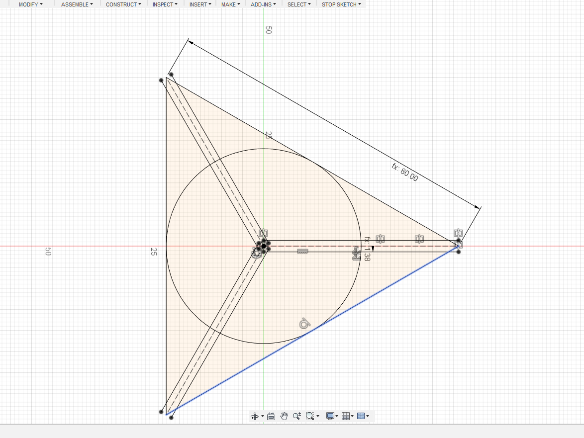 Made a tangent circle to work with the parametric concept
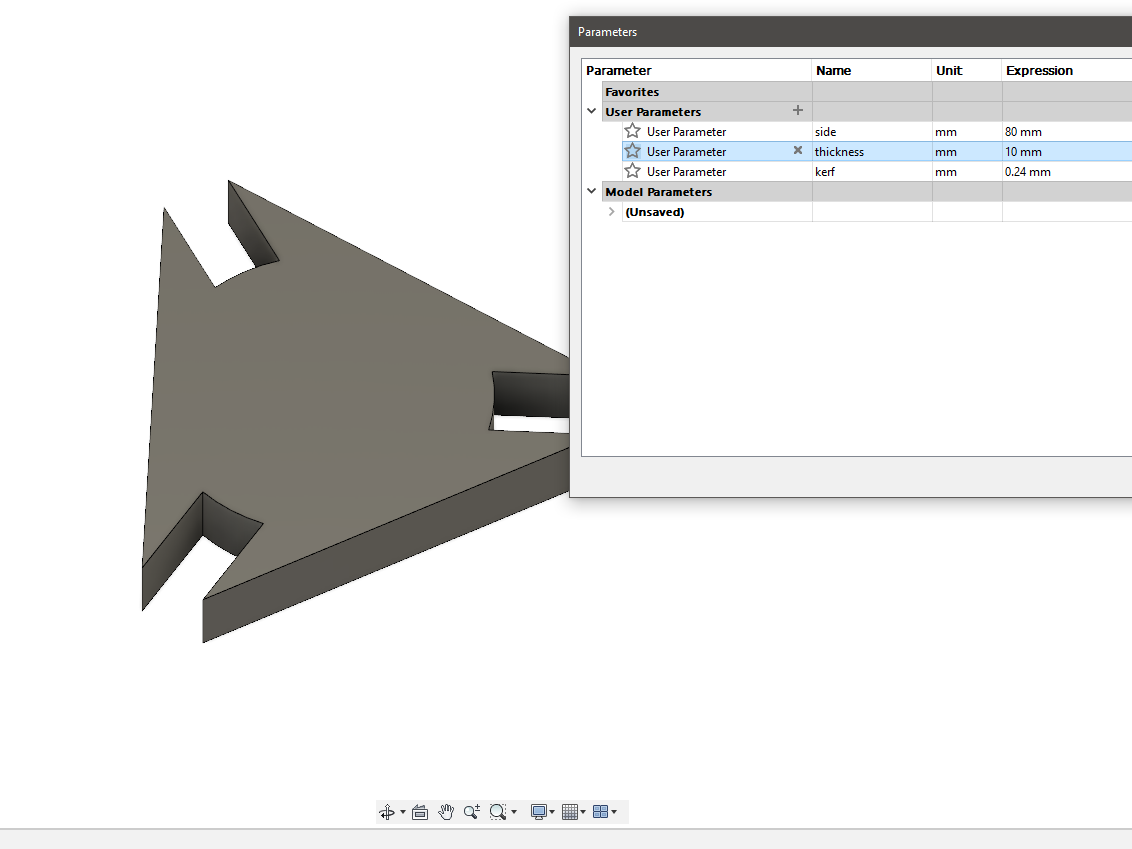
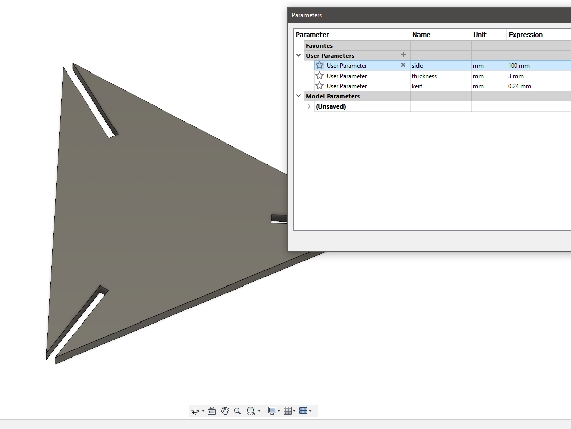
Tried various values to see the parametric approach sticks
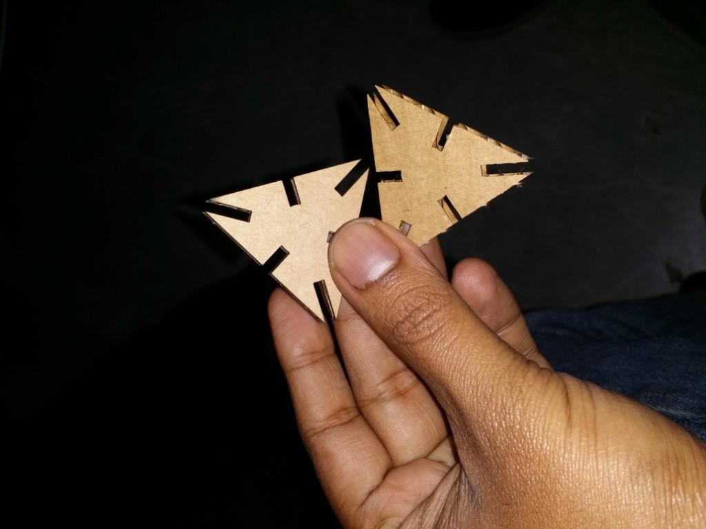
Two pieces were cut for testing the fit
The fit was a bit tight
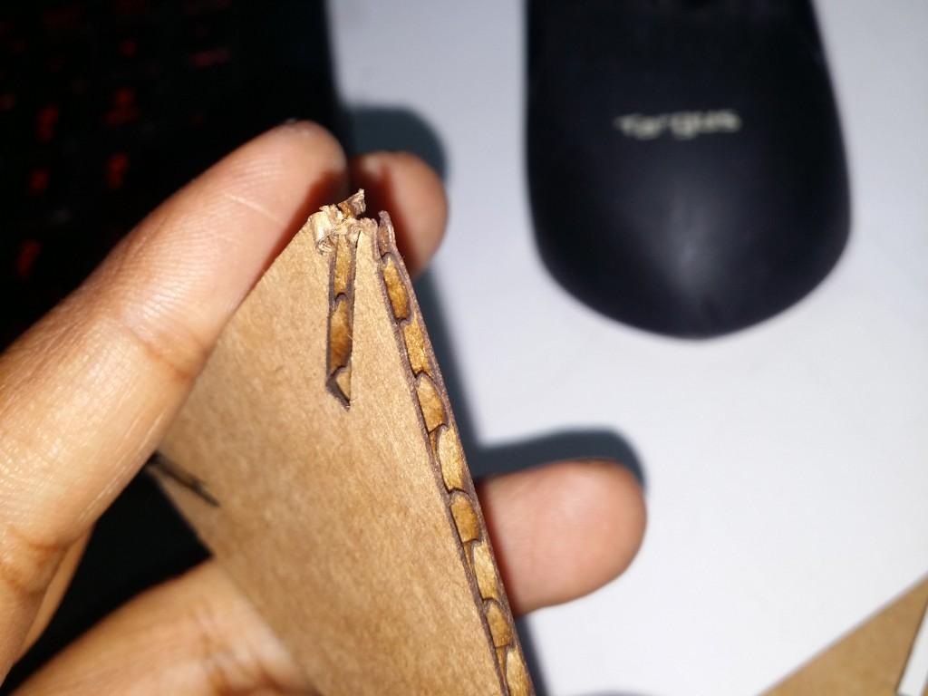
The corners got damaged since there is very little material there.
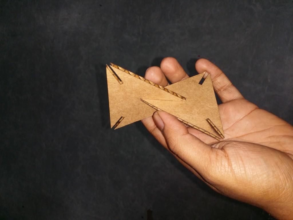
So I tweaked the design a bit and added slots at the edges as well.

Used a bit of maths to find the center of the smaller circles.

Rounded the corners for self centering
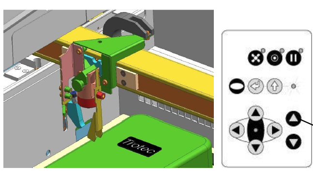
After designing the file, I kept a cardboard piece on the bed of the laser machine and used the laser focus tool and the arrow buttons for Z-axis on the laser machine for focussing the laser. This is a method without feedback. If your laser cutter is a bit old, there is a chance the actual focus maybe different. If that is the case, remove the focus tool and look at the laser dot on the cardboard as you move the bed up and down. The focus will be the best when the laser dot is the tiniest on the cardboard.
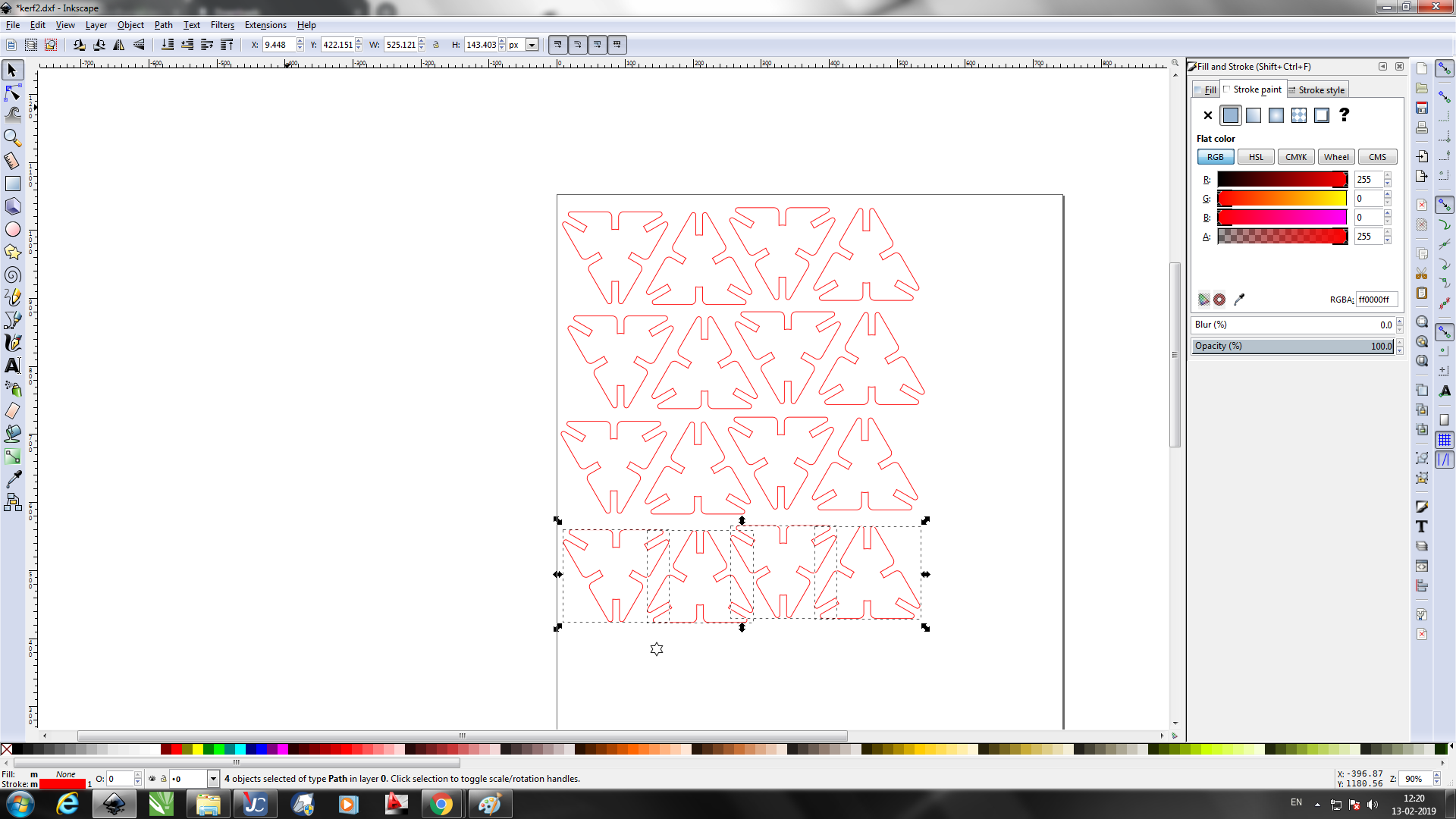
The dxf is imported to inkscape and the edges to be cut is given red colour. This colour can be chosen in the Interface of Lasercutter shown below. After the colours are corrected, the image can be sent for printing and select the trotec laser cutter as the printer. This will cause Trotec Interface to pop up.
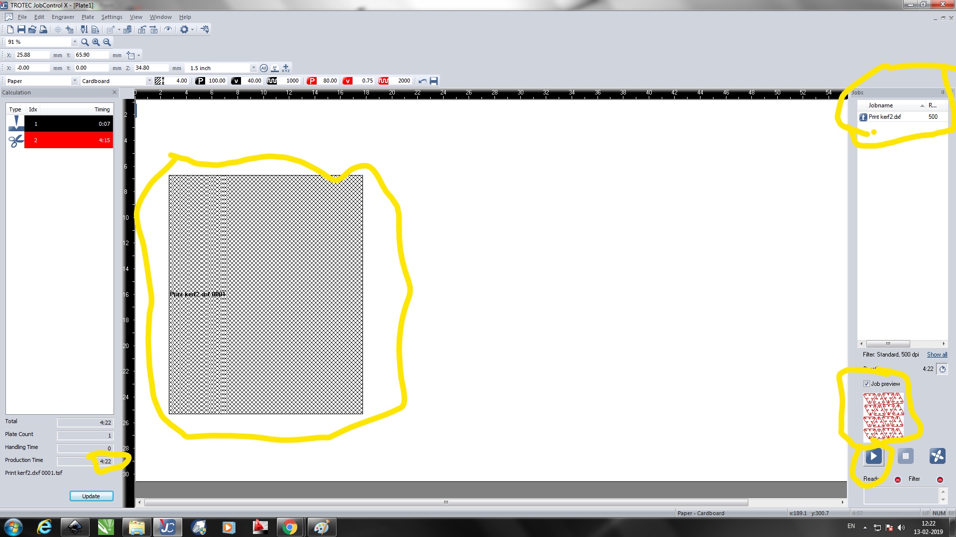
The file name will be shown in the top right corner. Double clicking on it will cause the previe to show in bottom right. A spatial representation of the file will be shown in the center. You can click and drag the same around to allign it specififcally with respect to the laser pointer head(which is shown as a cross hair in central white space). Estimated time to finish the job will be shown in bottom left corner. After everything is set-up, the file should be set to the laser cutter using the arrow button on bottom right.
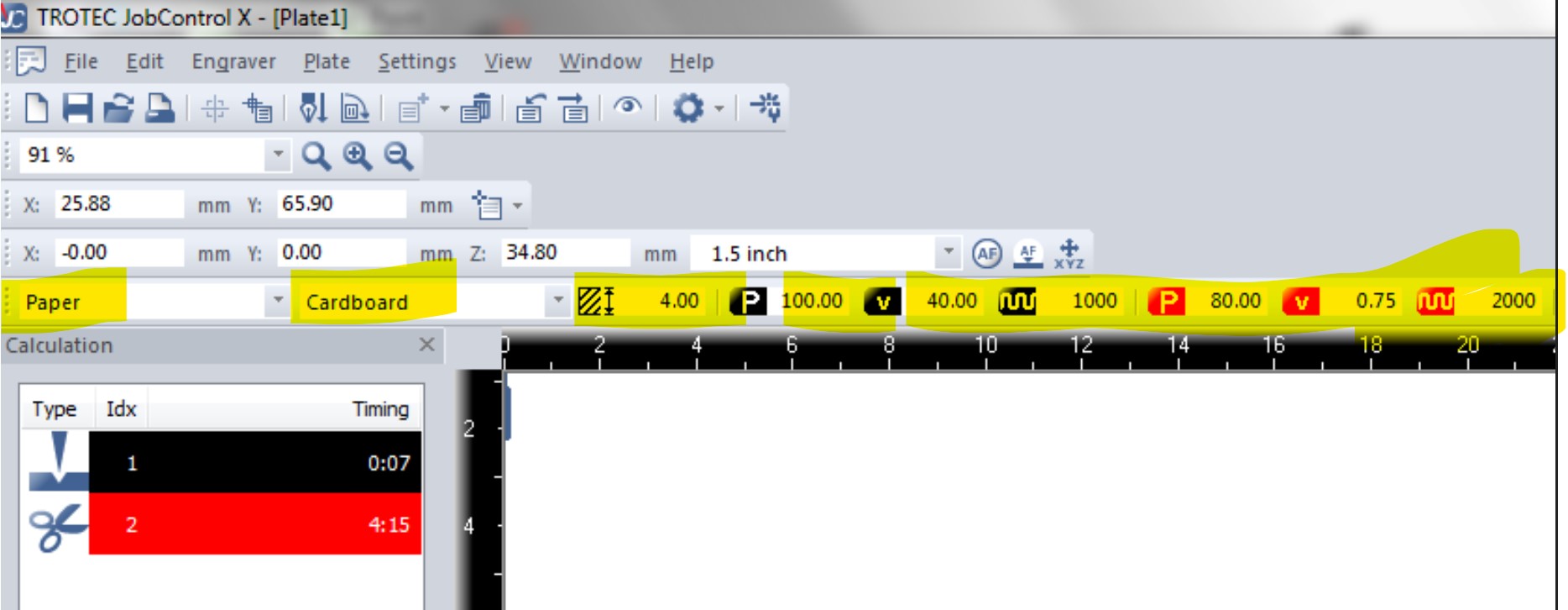
The top left corner is where you can select the generic material class, specific material type, thickness and parameters for the laser light to be used.
You can see there are black and red colours on the bottom left of the above image along with two distict icons to their left. Here black means engrave. (Notice the cut is not full in the icon.) The red colour shows a scissor icon which means this colour in the image will be cut.
On top right of the image you can see parameters P,V and a wave icon and a number to their right. P means Power, V means the speed of the laser arm, and sine wave means the frequency of the laser. These will be automatically set according to the material selected. But you could always override them if you wish. Please be aware that playing around with these values without fully understanding it might be dangerous since we are dealing with a powerfull laser here.
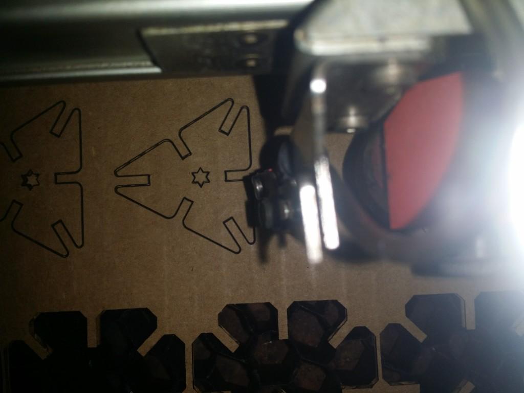
Cutting in action
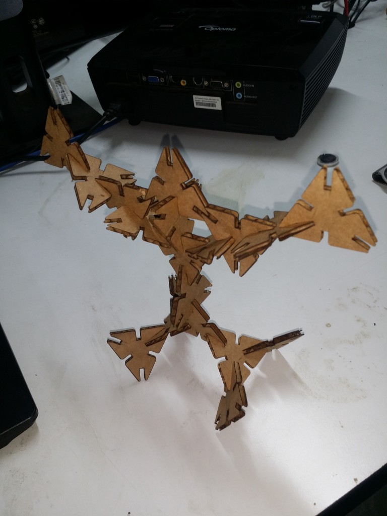
A construction with the cut kit. The star shaped central hole was avoided in final design because I felt it made the structure weak.
Download design files