5. Electronics production
This week we have to make a FabTinyISP. I did not know what that meant. A quick search told me that these are programmable componenets that can be programmed after the component is fixed onto a circuit. Which means, if you are using this component, you don’t have to buy them pre-programmed, it can be programmed after the complete soldering of the board.
PCB Milling
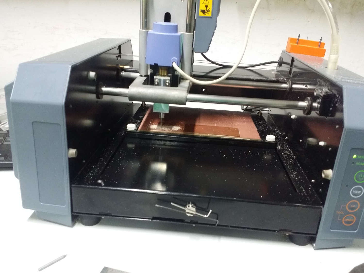
We are using the Roland Modella MDX-20 milling/scanning machine for doing the assignment. Pictures of the same can be seen at bottom
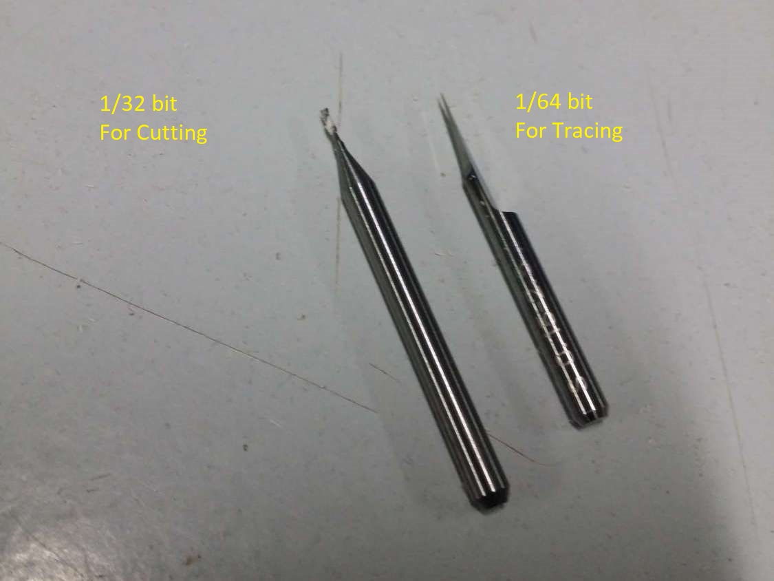
It shoud be noted that we have to physically change the milling bit in the machine and select the appropriate one in the interface. There are two types of bits used in this milling process. The one on the left hand side is used for cutting. Other one is used for tracing. The tracing should be done first following the cutting. If the cutting is done first, the tracing will fail because the cut PCB will move around while tracing. So we will load the 1/64 bit tracing bit first.
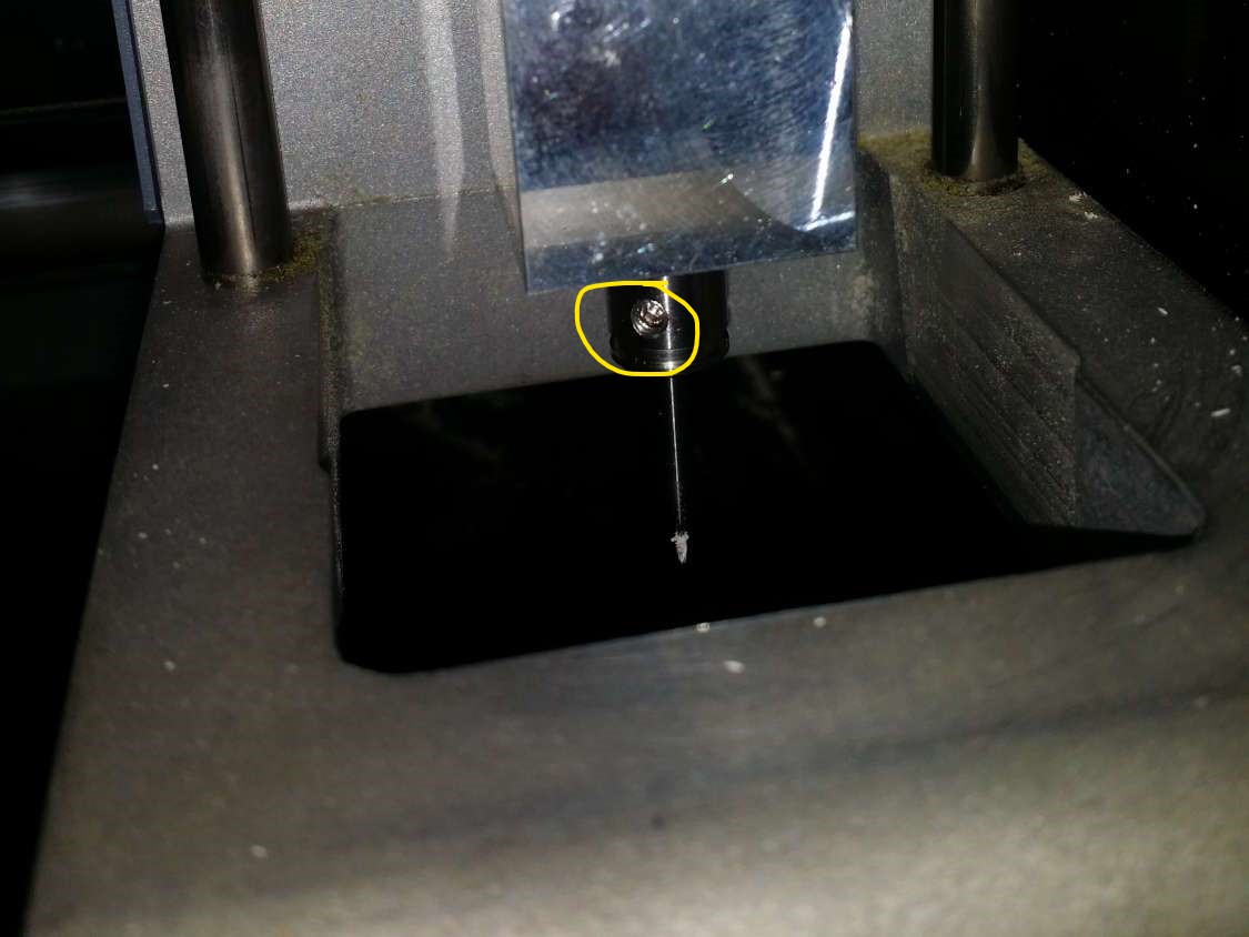
The tool bits can be replaced by loosening the allen nut holding it in the above picture
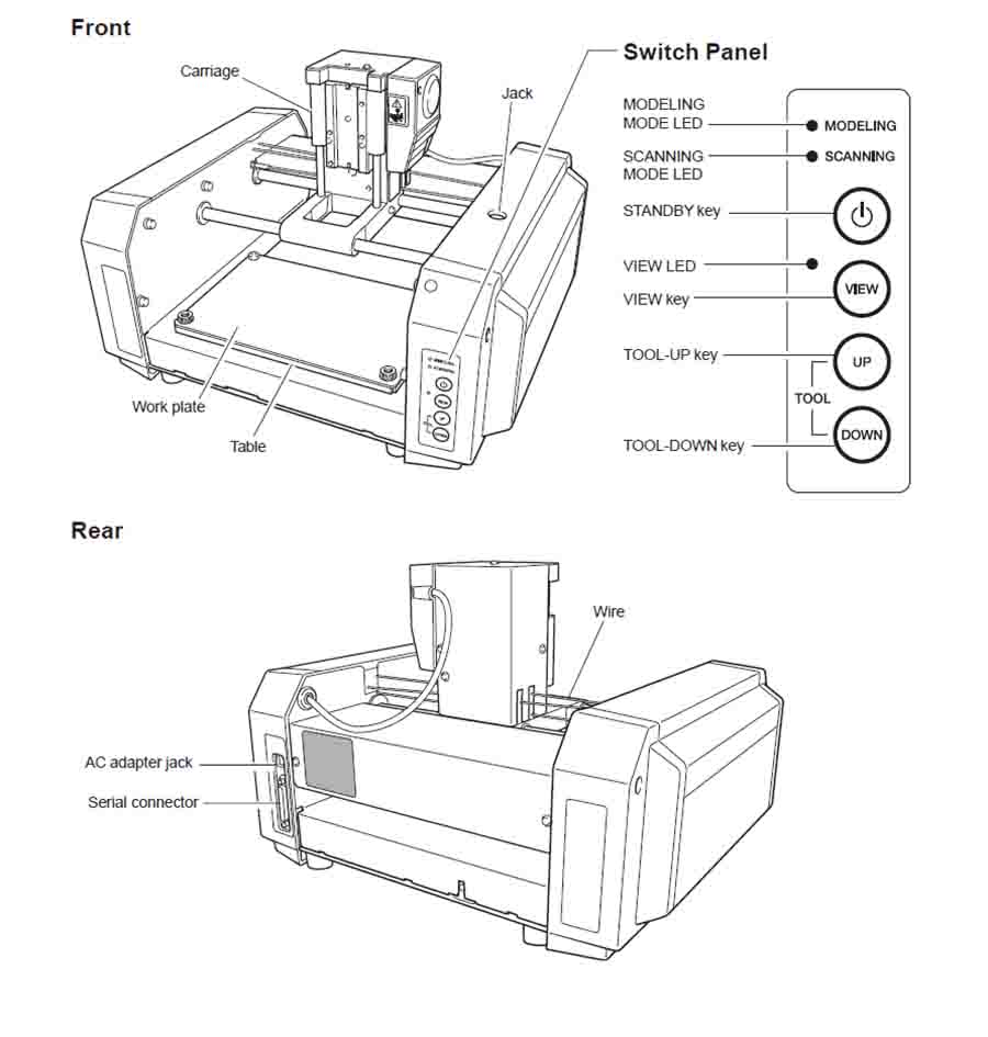
Press the view button after switching on the machine. The bed will come forward and you can easiy access the same now. The PCBs are fixed to the bed and to each other using double sided tape. It is extremely important to make sure the pcb is perfectly flat. Oherwise, the areas where the PCB is not stuck will have deep grooves and the ones which are stuck to the bed properly may endup without the trace.
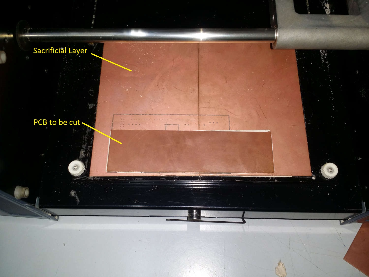
Note that we are using two sheets of PCB here. The one in the bottom is for protecting the bed against accidental cuts. If the bit goes too deep, the bottom layer will prevent it from cutting into the machine bed.
You can always check the level by following this work flow. After fixing the PCB in bed, press view so that the bed retracts and is below the cutting tool. Move the tool to x & y position using the interface. After the tool is at the required x,y position, use the up & down button on the machine to bring down the tool toward the bed, leaving 2-4 mm clearance between the bed and tool. Now loosen the allen nut so that the dril bit touches the bed. Fasten the nut at this position. Now move the bit around the entirety of the PCB and try to slide a paper between the tool and bed. If the paper slides, the bed is not level. If the bed is level, We can finally start the job.
The files were downloaded from MIT links attached in the bottom of this page.
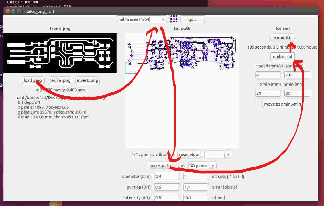
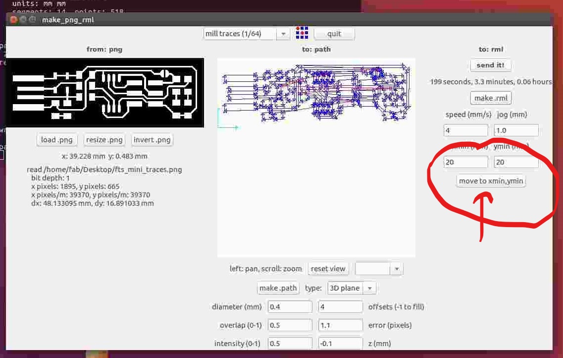
Milling was done via the mods interface, which we became familiar on 3rd week. Select Input file format >>Select the Machine >> Select work flow.
Load the file >> make path >> make rml >> send it to the machine and send to the machine interface. In the interface we can select the various parameters like speed, starting position milling/tracing depth & also importantly, the milling bit.
 Tracing Process
 After tracing. The paths looks a bit narrow. Upon closer inspection, I found the tracing bit end was slightly broken effectively making the bit tip wider. This made the trace paths wider than expected. However the PCB will serve the purpose and I went ahead to cut the PCB
Repeate the same process as done above exccept. - Physically change the milling bit to 1/32 - Load the file for cutting on mods - select the 1/32 bit on mods UI
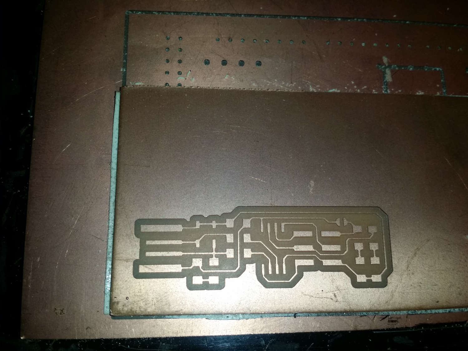
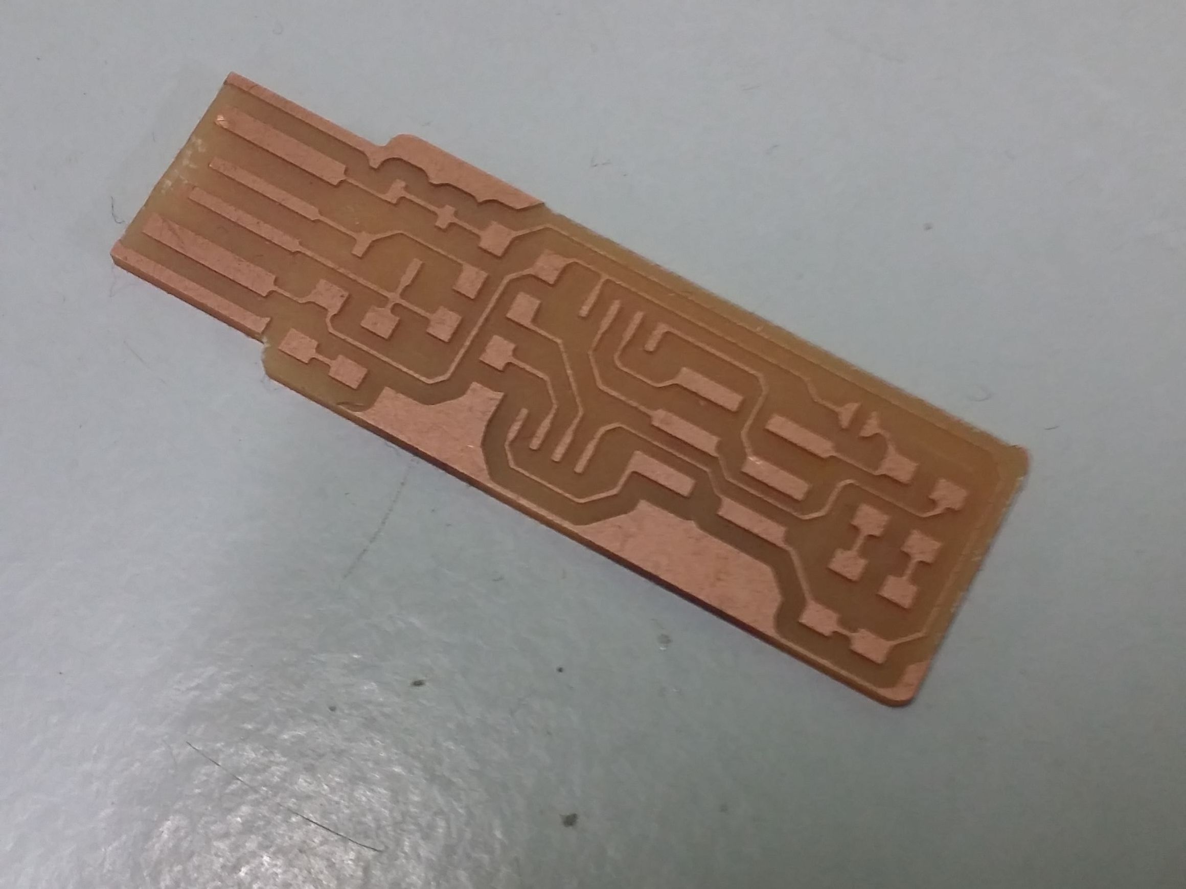 The final cut PCB
After the milling is done, check the continuity of the board with a multimeter to make sure no acciental discontinuity has occured.
Soldering
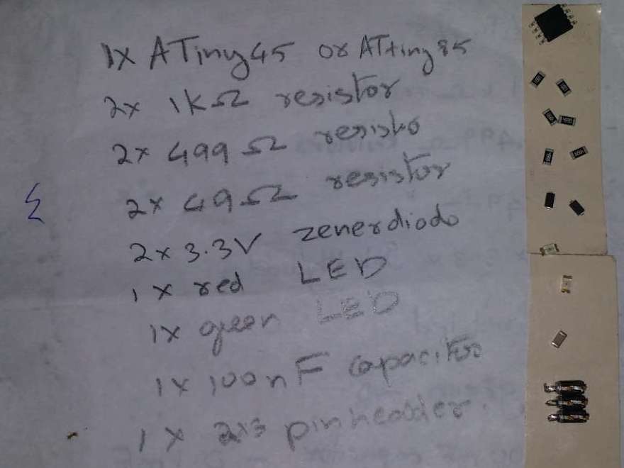 Before soldering, we have to write down the components required on a sheet of paper and stick a double sided tape to the side of it.
We can place the components on the side of it. This will keep everything in place and will help in preventing the mixup of the components.
Before soldering, we have to write down the components required on a sheet of paper and stick a double sided tape to the side of it.
We can place the components on the side of it. This will keep everything in place and will help in preventing the mixup of the components.
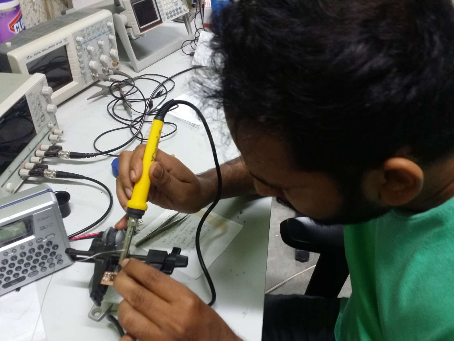 As a thump rule, we should start soldering the complex parts first like the IC & move onto smaller parts. But since I have not used a soldering iron in years and also remembering the concept of semiconductor devices failing when exposed to a high temperature for prolonged time, I decided I will start with resistors >> capacitor >> diodes >> LEDs >> IC
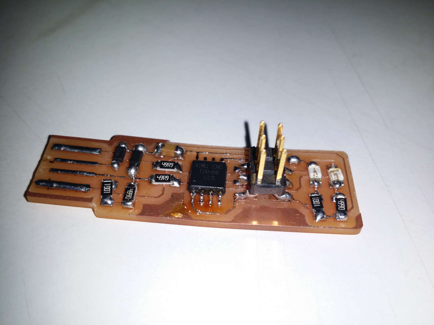 Final Circuit after soldering
Software Installation
We need some kind of a software to connect our newly made device to a computer. Since I am using a windows PC, I used this guide to setup all the software. I did progrrame my programmer according to that guide. But did not understand what I was doing. I will make another ISP & do the programing again to understand it clearly
Download files