Group Assignment: Mechanical & Machine Design
The goal for this week's assignment was to design a machine that includes mechanism, actuation and automation. Bulid the mechanical parts and operate it manually.
Brainstorming
We've had some ideas for this assignment: Juicer, Fab-Tour Bot, Robotic Arm. For each of them we created a concept before we decided what to do.
Juicer: Requirements
Fab-Tour Bot: Requirements
Robotic Arm: Requirements
After spending weeks on deciding what to make ranging from an Juicer to a Fab-tour Bot, we finally decided on making the Robotic Arm.
Robotic Arm: Technical Concept
Mechanical Design: Planetary Gears
Alessandra Crotty worked on the bottom part of the robotic arm. For the mechanical part she developed a planetary gearset to distribute the weight among several gears. Any planetary gearset has three main components:
Each of these three components can be the input, the output or can be held stationary. Choosing which piece plays which role determines the gear ratio for the gearset.

In this case, the planet wheels and the planet carrier are the ones that are kept stationary, while the ring gear is the one that moves. Planetary gears are often used when space and weight are an issue, but a large amount of speed reduction and torque are needed.
Mechanical Design: Grabbing System
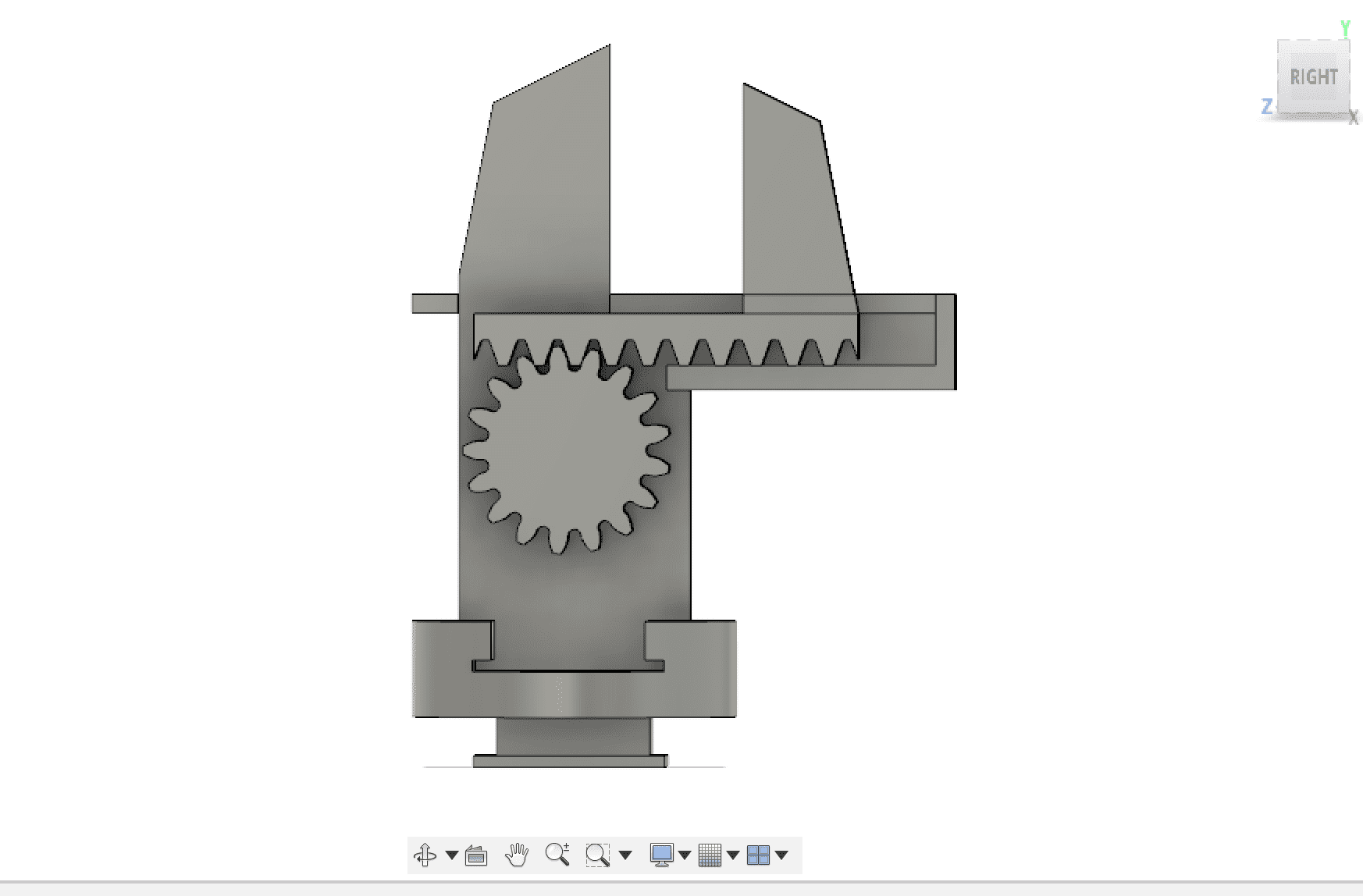
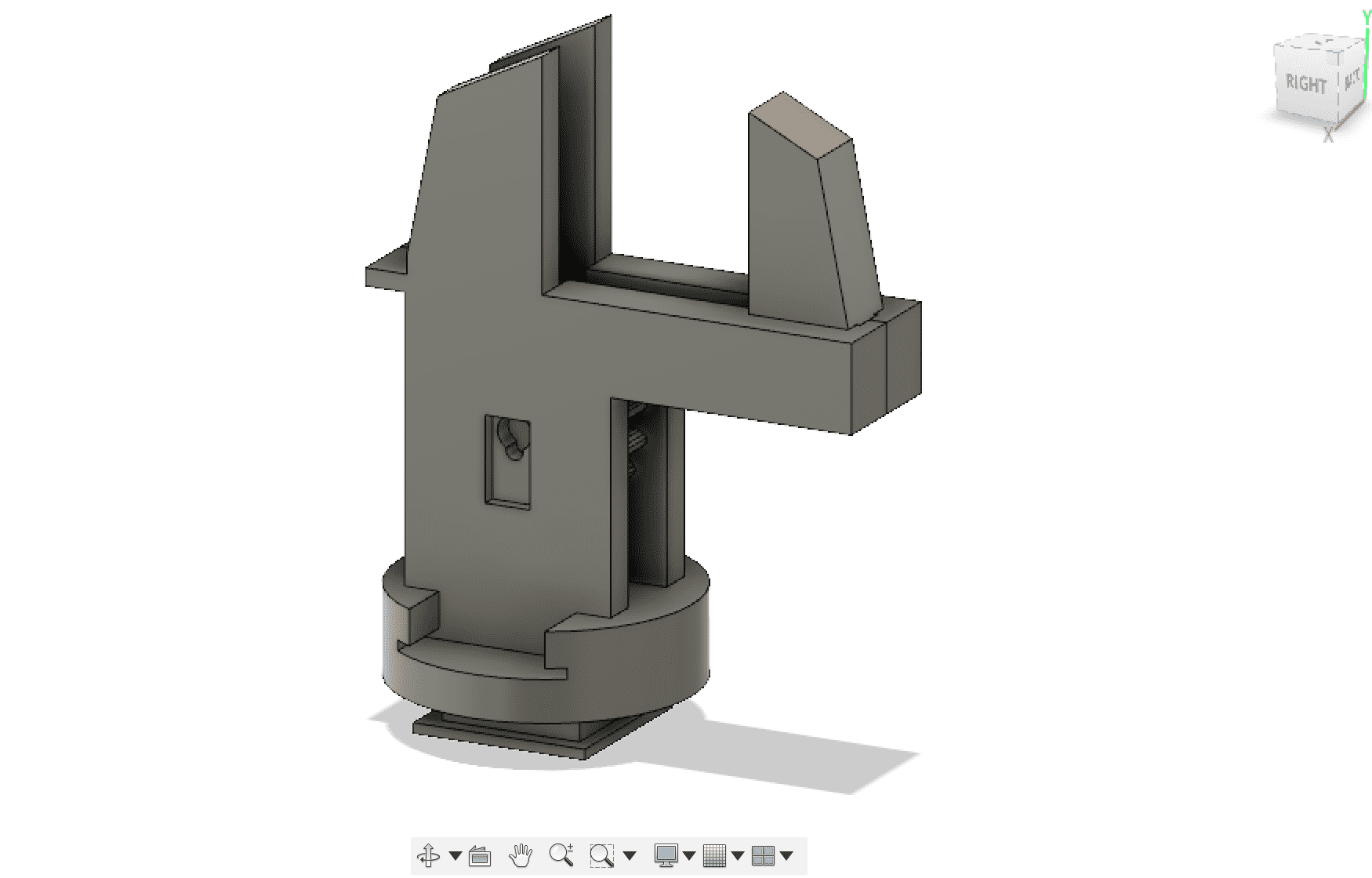
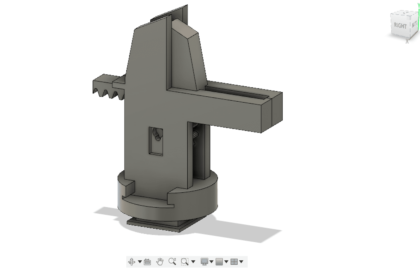
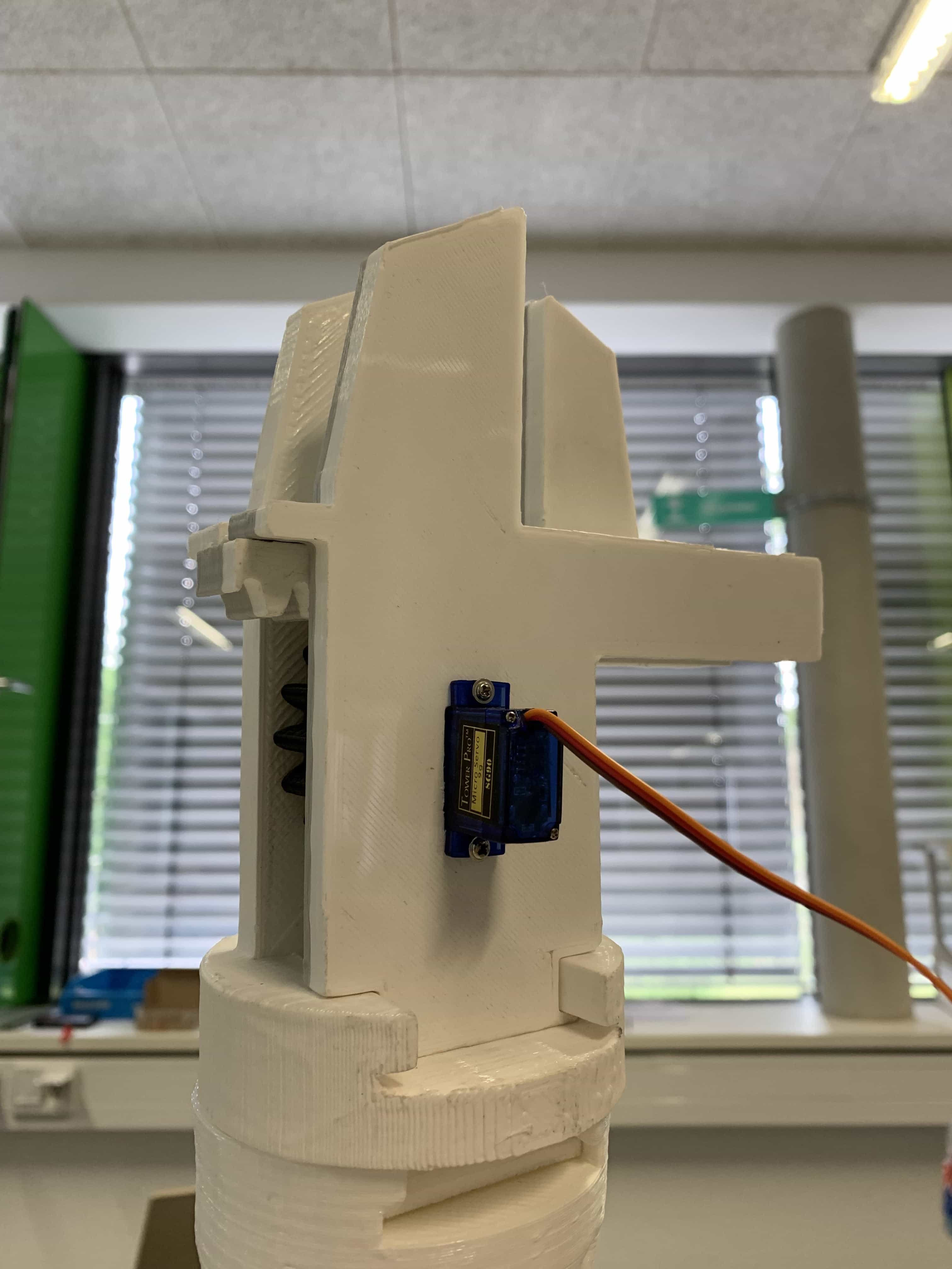
Hakan Zayin created grabbing system of the arm. He was looking for different ways to grab objects. After a while he decided to use a servo motor to move a gear that moves a linear gear to open and close the hand.
Machine Design: Arm Design
Markus Fleischer devoted himself to the design of the shape of the arm, because of the experiance he has as a 3d-artist. He designed everything in Blender.
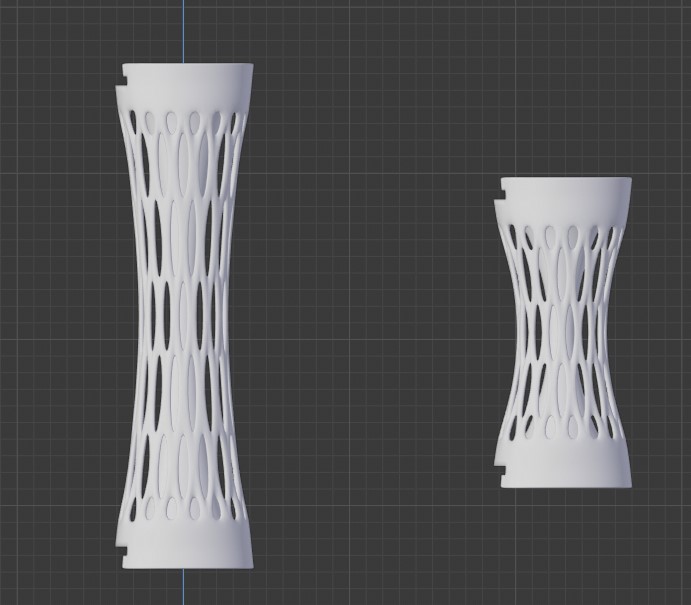

At some point it turned out that parts of the arm where way too heavy, which stopped the arm from moving, so Florian Schaefer exchange each connection-element of the arm for a much smaller version. All adapters have a length of 4cm and are of the same diameter as the base elements of the original connectors.
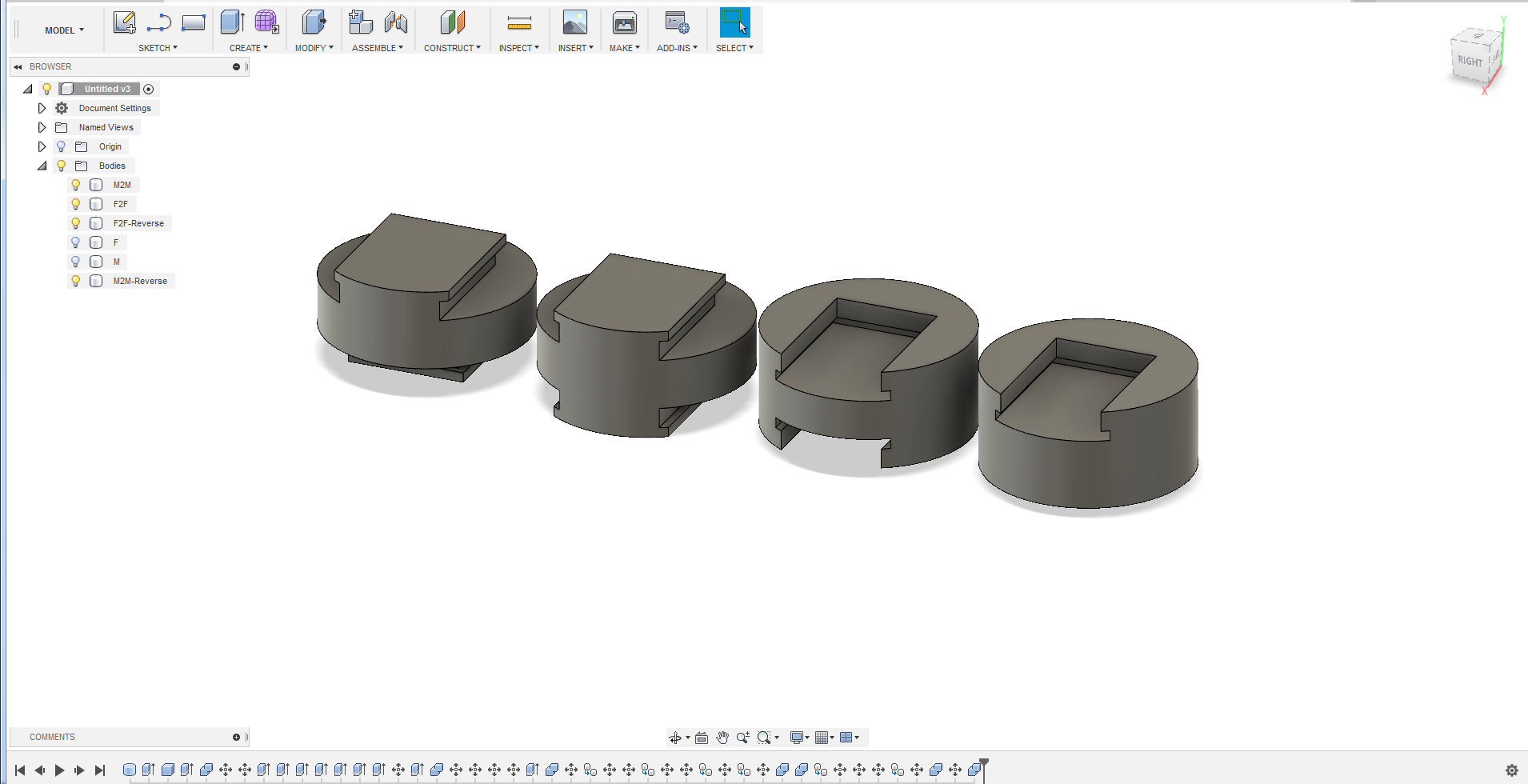
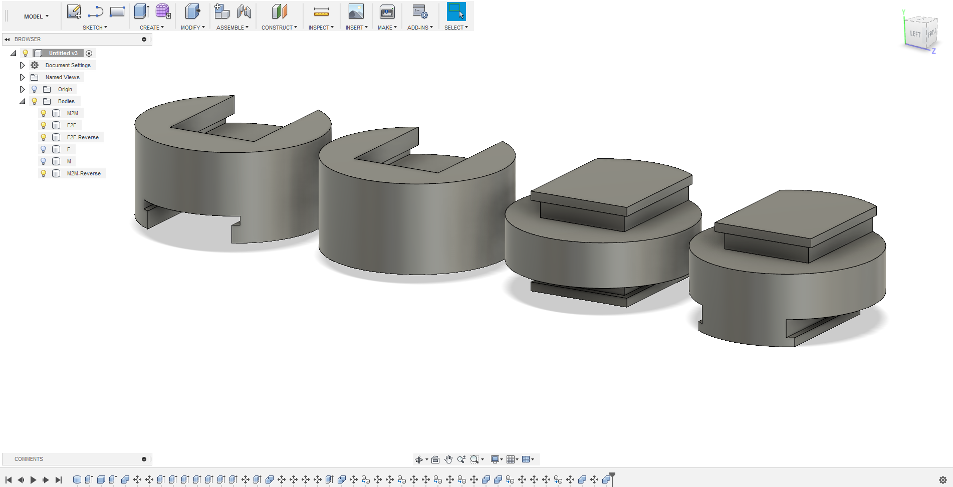
Machine Design: Modular Joints
The joints are designed to make the whole arm modular, so every 'bone' can easily be swapped out for another one. This actually helped us in the long run, but more on that later.
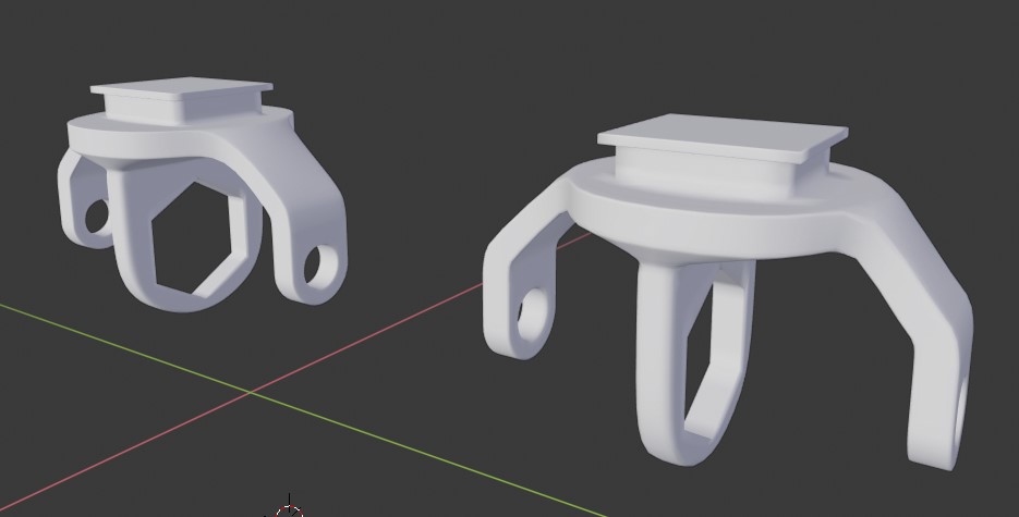
TThis is what it looks like put together.


Hakan Zayin created the upper joint that holds the stepper motor. Because we wanted the arm to be light so it could move easily, he chose a honeycomb pattern to save weight.
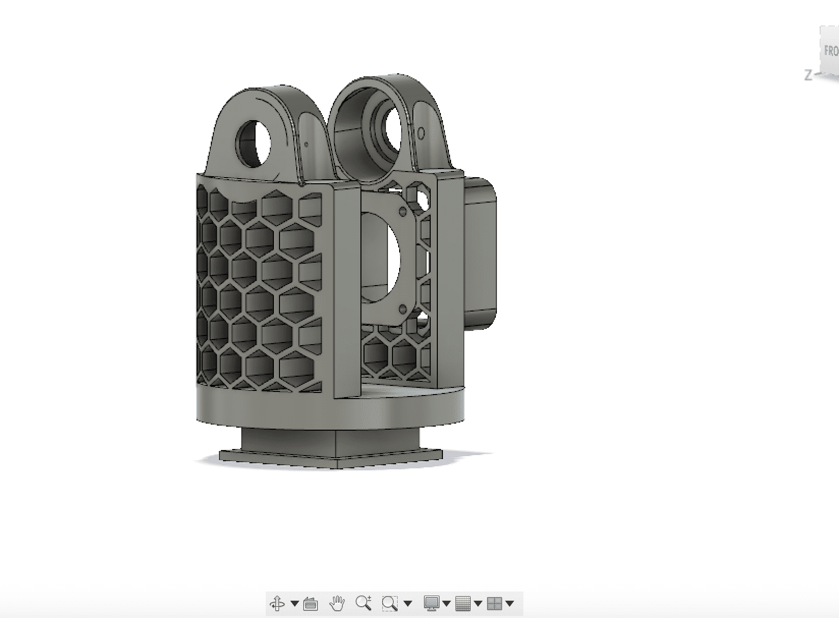
Machine Design: Bottom Part
Alessandra Crotty designed the bottom part, which contains the planetary gears.


Alessandra Crotty also worked together with Christian Schendera, a student who volunteered to attend the FabAcademy. He designed the joint to attach the arm to the base.

The stepper motors we use to turn the joints are only based on a torque of 28 nanometers. We didn't want to increase the size too much. So we wanted to increase the power without increasing the weight on the arm with a stronger but heavier motor.What we have decided is a mechanism that increases torque and reduces speed. We came from a small 18mm diameter gear to a larger 64mm diameter gear and hoped it would be strong enough. In the middle of the two large gears we insert a 14mm ball bearing running on an 8mm thread.In order to hold the shaft and also the motors, I built two houses, which are individually designed and fit perfectly to the specific parts. On the upper part there is space for the same ball bearings, which are inserted into the gears.


Microcontroller Board
Alessandra Crotty also made the microcontroller board for this week's assignment. She decided to use a Atmega1284, since it has more pins and we are going to use 5 stepper motors and one servo motor.


Coding
Alessandra Crotty worked on a code that rotates the bottom part of the robotic arm as soon as you enter a value into the serial communication.
// defines pins numbers
const int stepPin = 3;
const int dirPin = 4;

// Stepper Travel Variables
String incomingData;   // for incoming serial data
int val = 0;	// parse the incoming data to an int

int enable = 13;

void setup() {
  // Sets the two pins as Outputs
  pinMode(stepPin,OUTPUT);
  pinMode(dirPin,OUTPUT);
  pinMode(enable,OUTPUT);
  digitalWrite(enable,HIGH);	//disable the motors
  digitalWrite(dirPin,HIGH);	//rotates the motor clockwise

  Serial.begin(9600);  // Start the Serial monitor with speed of 9600 Bauds

// Print out Instructions on the Serial Monitor at Start
  Serial.print("Enter Move Values Now: ");
}

void loop() {

 if (Serial.available() > 0) {

                incomingData = Serial.readString();
                val= incomingData.toInt();
                Serial.println(val);
                digitalWrite(enable,LOW);	//enables the motor

        }

  if (val > 0 ) {
  // Makes 800 pulses for making one full cycle rotation
  for(int x = 0; x < val ; x++) {
    digitalWrite(stepPin,HIGH);
    delayMicroseconds(500);
    digitalWrite(stepPin,LOW);
    delayMicroseconds(500);

   }
   val = 0;
   digitalWrite(enable,HIGH);
   }
}
In the meantime Florian Schaefer worked on a code to address all motors.The software is controlled over the serial monitor and can be used to learn about the way the robotic arm makes it's movements. Later the target values could be pre-defined or even calculated on the go. The only thing really needed is a reliable zero position, otherwise movements can not be reused. Complex tasks could be fulfilled by chaining multiple calls to moveTo. A problem with this code is that it's still moving step by step and has no concept of acceleration and deceleration.
#include <Stepper.h>

Stepper motors[] = {
  // The first value is the number of steps the motor needs for one revolution, adjust it accordingly
  Stepper (200, PA0, PA1, PA2, PA3), // Base
  Stepper (200, PB0, PB1, PB2, PB3), // Joint one, just double the wires to send the signal to both motors
  Stepper (200, PC0, PC1, PC2, PC3) // Joint two
 };

// This can be any position of the arm but the movements will be relative to it
int steps[] = {0, 0, 0};

// fin[] and finCount have to be reset before a new target
boolean fin[] = {false, false, false};
int finCount = 0;

// These are used to hold the serial input
int a = 0; int b = 0; int c = 0;

void setup()
{
    Serial.begin(9600);
}

void loop() {
  Serial.flush();
  Serial.write("Enter target position");

  Serial.write("Base");
  while(!Serial.available());
  a = Serial.read();
  Serial.flush();

  Serial.write("Joint 1");
  while(!Serial.available());
  b = Serial.read();
  Serial.flush();

  Serial.write("Joint 2");
  while(!Serial.available());
  c = Serial.read();
  Serial.flush();

  moveTo(a,b,c);
}

void moveTo(int baseTarget, int jointOneTarget, int jointTwoTarget){
  while(finCount < 3){ // When all three have finished we are done
        //Move each motor one step towards the target positiont
        moveMotorOneStep(0, baseTarget);
        moveMotorOneStep(1, jointOneTarget);
        moveMotorOneStep(2, jointTwoTarget);
    }
}

void moveMotorOneStep(int motor, int target){
    if(steps[motor] < target){ // We need to move forward
              motors[motor].step(1);
              steps[motor]++;
            }
            else if(steps[motor] > target){ // We need to move back
              motors[motor].step(-1);
              steps[motor]--;
            }else if(fin[motor] == false) { // we are in the target position
              fin[motor] = true;
              finCount++;
           }
}
