4. Computer controlled cutting
This week is so exciting for me because we will start using the machines! I love this part so much, that try and error to achieve your product.
The assignments will start from this week to split to group assignment and individual assignment.
The assignment for this week
My start point
After reviewing the lecture and exactly the assignment, I started researching and I stuck in the research about 10 hours to move to the next step!!
I’d love to document the journey of the research because I’m sure that I will back to these links recently. If you would like to review this part it could help you to get new ideas.
Some project that I loved and learned from each one.
-Lara Tomholt -Kathy Sinclair -Joris Navarro/ -Kurina Sohn I loved this website at all. -Óscar González Fernández -Javier Alboguijarro I loved this documentation so much, It’s very simple and high value! -Daniel Bruns -Yogi Kulkarni recommended two valuable links Desert Domes and Domes calculation -Sam Calisch -Bucky Ball with Aclyric -cardboard Box -Dome -Hjörtur Sigurðsson -Geometry -Hexagon fixation -Hexagon fixation -Wireframe Hexagon -Joints and members Vault -ChiangYC
After this long research, I decided to make a geodesic Ball from Hexagon and pentagon shape, and during the design stage, I decided to add a triangle with pentagon as another kit.
Steps for me to get started
-Research for the kit that multiple uses. -Design it with machine rules. -Learn how to use the machine. -Test machine: -In laser cutting to determine your kerf based on power, speed, and focal length. So we need to make the group assignment first. -In Roland “vinyl” the machine makes self-test to choose the default power and speed, I loved this smart machine so much and hopefully, laser cutting does the same function! -Edit in your design parameters based on the kerf and the thickness of the material. -Make a test for little parts to reduce the rest. -Integrate the press-fit parts, and make sure if you need. -Redesign the kit. -Finally, cut it and enjoy!
Design Process
Kit 1
I saw this design serval times, It’s amazing. It’s a very simple design, it doesn’t take a lot of materials and multi of this shape can make wonderful geometries. So, I want to try it!
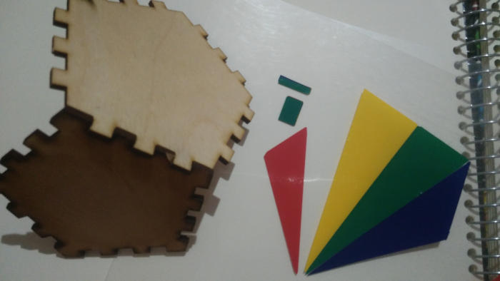
Kit 2 - Pentagonal Rotunda Dome
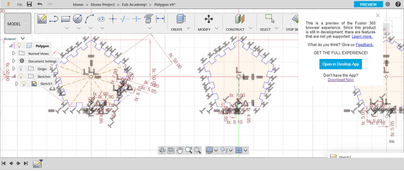
I started this week with Fusion 360 to learn more about different software issues. I prefer this way to learn more and more.
I record a video for me through I draw this kit, so if you have time, you can watch the whole process that I took to design parametric icosahedron by Fusion 360.
Parametric Icosahedron with Fusion360
This video can explain How to Draw Parametric Icosahedron with Fusion360
Draw Parametric Icosahedron in Fusion 360 to laser cutting from Nada Gamal on Vimeo.
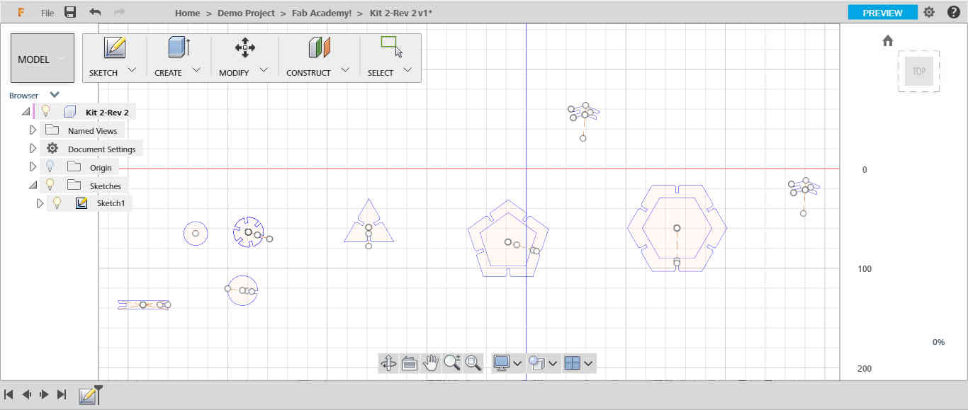
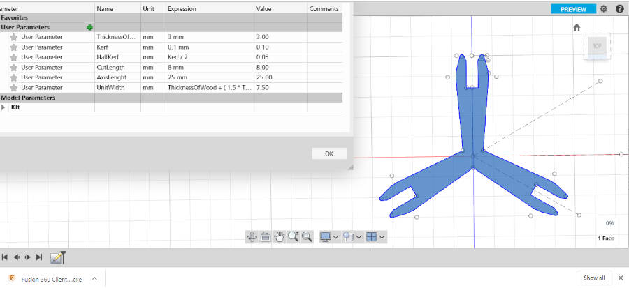
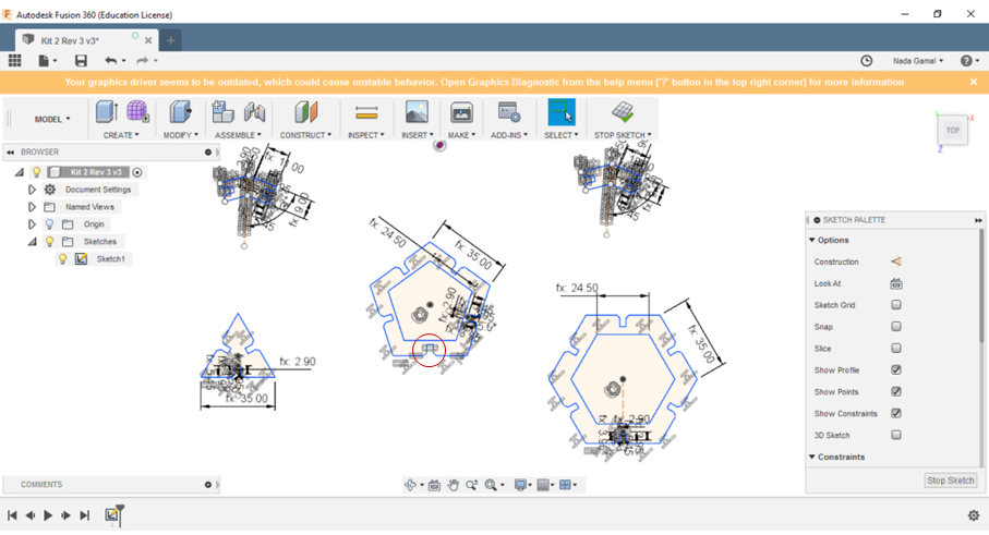
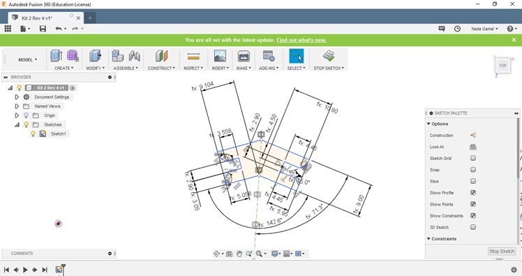
- These are the shapes that we need for our kit. The circular parts that optional, that we can use with these parts to make another kit.
- The most critical length that will control in the scale of our kit is the length of the icosahedron Not the outer or inner diameter of the polygon circle. This is the first fault I did in my design then I edit it.
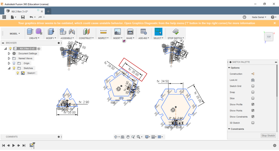
- I changed the length value from 35 to 50 to make sure that my design is parametric.
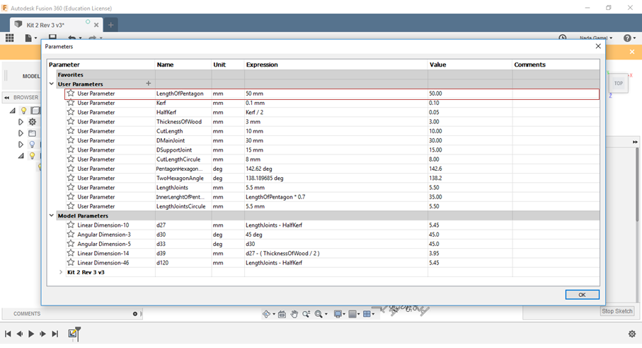
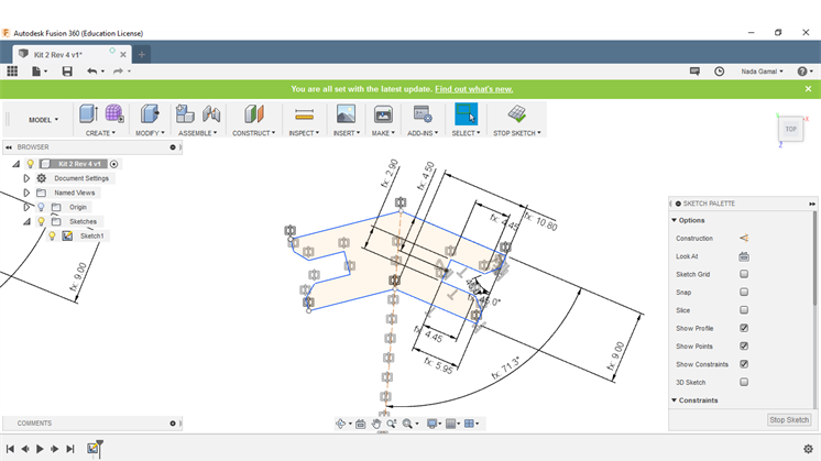
- You can notice that the whole shapes change directly with the length value.
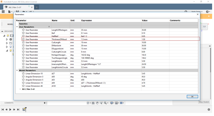
- Also, the thickness of wood, if we decided to use another material with another thickness, it’s very easy to edit it.
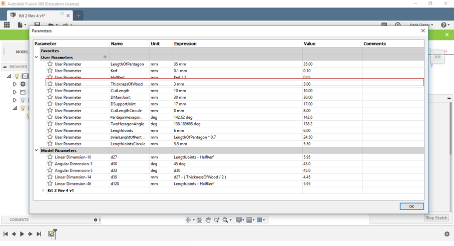
- We changed the thickness of material from 3mm too 1.5mm as a sample.

- Also, this part is the fixation between the pentagonal and the triangle. So if we decided to edit the design with different shapes as for example pentagonal and hexagon, the fixation part needs another angle. So it will be very easy if we designed this part parametric.
- Also, the thickness of the material and the kerf value…
Kit 3 - Dodecahedron
The Dodecahedron is any polyhedron with twelve flat faces. So I choose the Regular Dodecahedron as a simple shape to design. Also, I want to test different press-fit joint techniques.
We noticed that I have five different shapes of my object in the press-fit joint to make the twelve faces press-fit together.
-
After I finished my design, I tried to change in the parameters, but nothing changes and all dimensions changed to the Cashmere pink color as a preview, and it means we fixed more than one parameter that the object will be changed based on, and we change just one parameter. So, the object can’t help me to be parametric.
-
I took a lot of time to edit this error but I failed in it!
-
It remembered me when I designed wireless steering wheel game controller with Golden Ratio concept, in Advanced Maker Diploma, and I faced the same error, but for golden ratio concept there are no Solutions instead of just make a scale for the whole object!
But for this shape, it’s very easy to edit, but I can’t find the exact fault constraint right now!
So I will start to finish other kits and back to this design later…
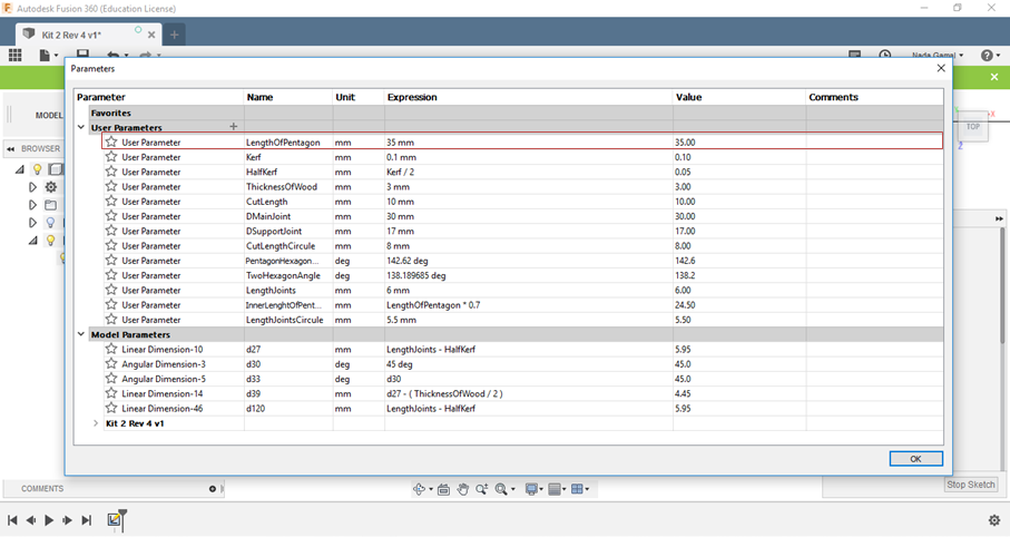
The parameter setting that I used.
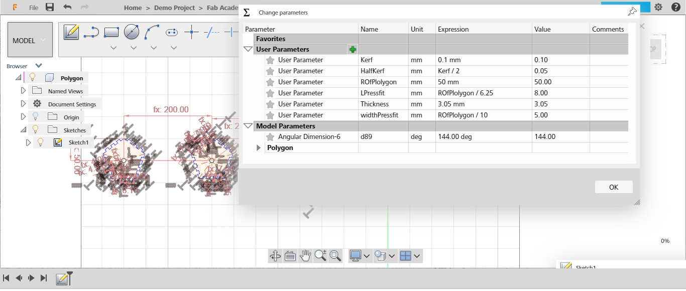
Now I’m ready to visit the maker space with my designs!!
Laser Cutting Machine
The first step, we need to characterize our machine ‘is MT3050DIII‘ to edit the kerf value, speed, and power. That will reflect in our designs.
We made this step with Haggag our instructor, he recommended to review Haithem Abdelkhalek documentation for this assignment, and download the design files of the group assignment to test the machine.
We just follow his documentation and made the same steps.
This image from Haithem Abdelkhalek website. That we followed his documentation.
First, we need to test the speed and power for cutting and engraving process. Then we choose the default value after that we test the Kerf value.
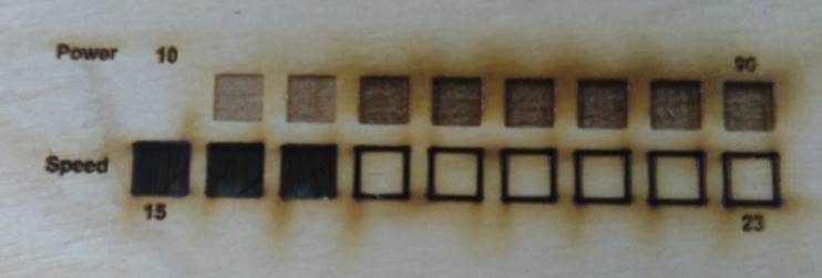
- So, this is the speed and power for cutting and engraving process test.
- The cutting speed started from 15mm/s to 17mm/s, and power 75%, it’s good. From 18 mm/s it doesn’t work.
- For the scan process, ‘Engraving’ with the Constance speed 200 mm/s and the power is 10%, it doesn’t work. For 20% and 30%, it’s fine. But I think the engraving result based on the depth that we need to engrave.
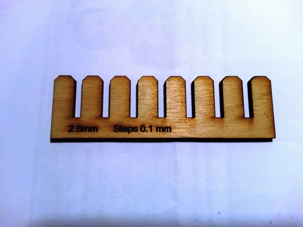
Then, we started to test the kerf value with the current focus length is matched with the third joint. The width in the design file, equal to 3mm but when we measure it, it equals to 2.8mm.
So, that’s means the Kerf value equal to 0.2 mm.
Also, Lamia made the same tests but with another depth of the focus length. And she reached to kerf value with 0.1 mm. And with the speed and power, I think the finish of the sheet in her test is more clear than my results.
So, we work in her results…
After the test, I edited my designed with the kerf value and the next step to prepare my sheets to be cut.
Export Files Process
I loved this way, it’s not the default but it’s easy for me.
-
Saved the file as DXF.
-
The default way our maker space in FabLab Egypt use is open the file in Coreldraw to edit the design and convert it to laser work “laser work” the software of laser cutting machine”
-
Honestly, I didn’t love the interface of Coreldraw and we don’t match together!
-
So usually I use AutoCad to edit my design then save as DXF or PDF and open it directly in laser work.
But this time I changed my windows and didn’t install AutoCad yet, so I used Rhinoceros.
-
Rhino can import DXF files and export it DXF also. Acutely this amazing software has many extension to import and export.
-
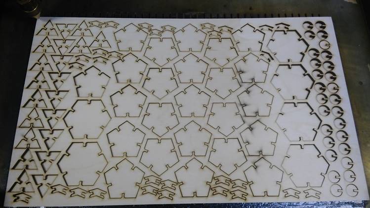
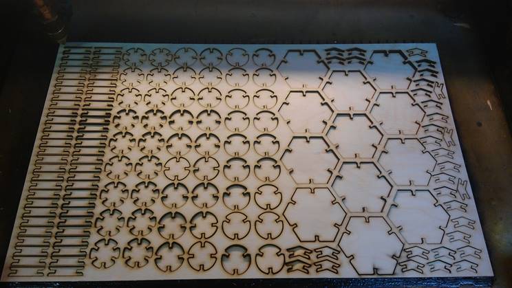
Then I edited my sheets with the dimensions of our machine “MT3050DIII” is “500 * 300 mm” and repeater my parts of kit as I need.
-
I tried as possible to save the waste of the sheet and used every inch in the sheet.
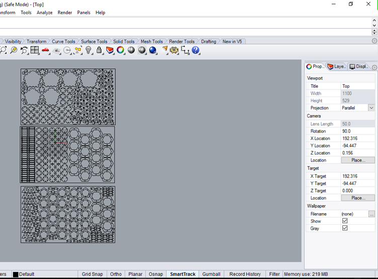
So, I will use three sheets of plywood with 3 mm thickness.
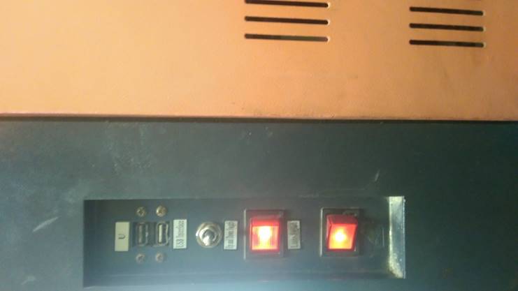
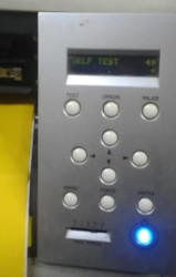
Every time I use the laser cut I turn on one button! And start asking why the machine doesn’t respond!
So I decided to document this point!
We need to turn on the two buttons!
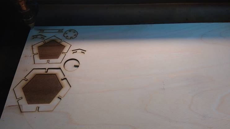
I started with a small test of my parts to make sure of my whole design.
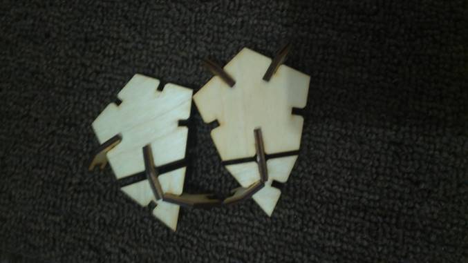
Different values of the slot length will affect the distance or proximity of the sides of each other.
We noticed that there are different colors in the same sheets, some of the parts were burned and a little of them is fine
That’s because we have a big issue on the machine plate, the Z direction of the plate is not constant! I know that the sheet dimensions are not big to have this issue but unfortunately, this is the real!
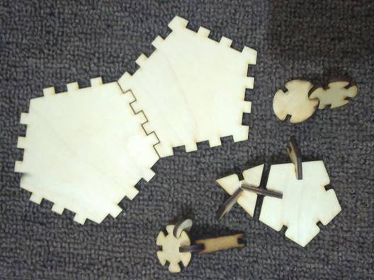
So I decided to not continue, I will be enough with only two sheets!!
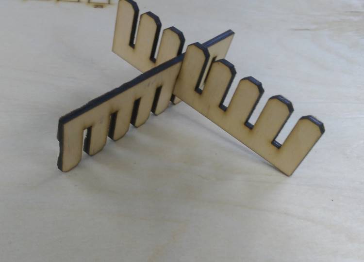
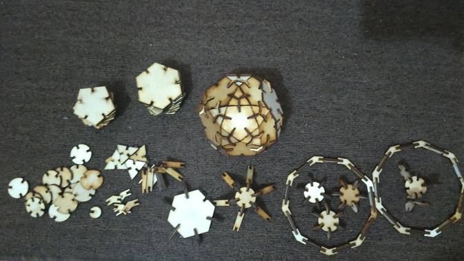
I tried to make my kits with these parts, and I didn’t make the whole ball that I wanted. But I made a Dome ‘ half of the ball’ and it works!!
So you can use the same file design with a good machine and will get the perfect result!
Redesign the Geodesic Ball with Grasshopper
I didn’t feel well with Fusion360 as a parametric tool … I spent a lot of time in export my files as dxf from fusion to open in rhino to edit my parts in the available dimensions sheet and when I change the kerf parameter in fusion , I redo all this process!
So I thought if I make all this process from A to Z in Grasshopper it will be easier!
From here I decided to continue with Grasshopper as a parametric tool.
First Trail
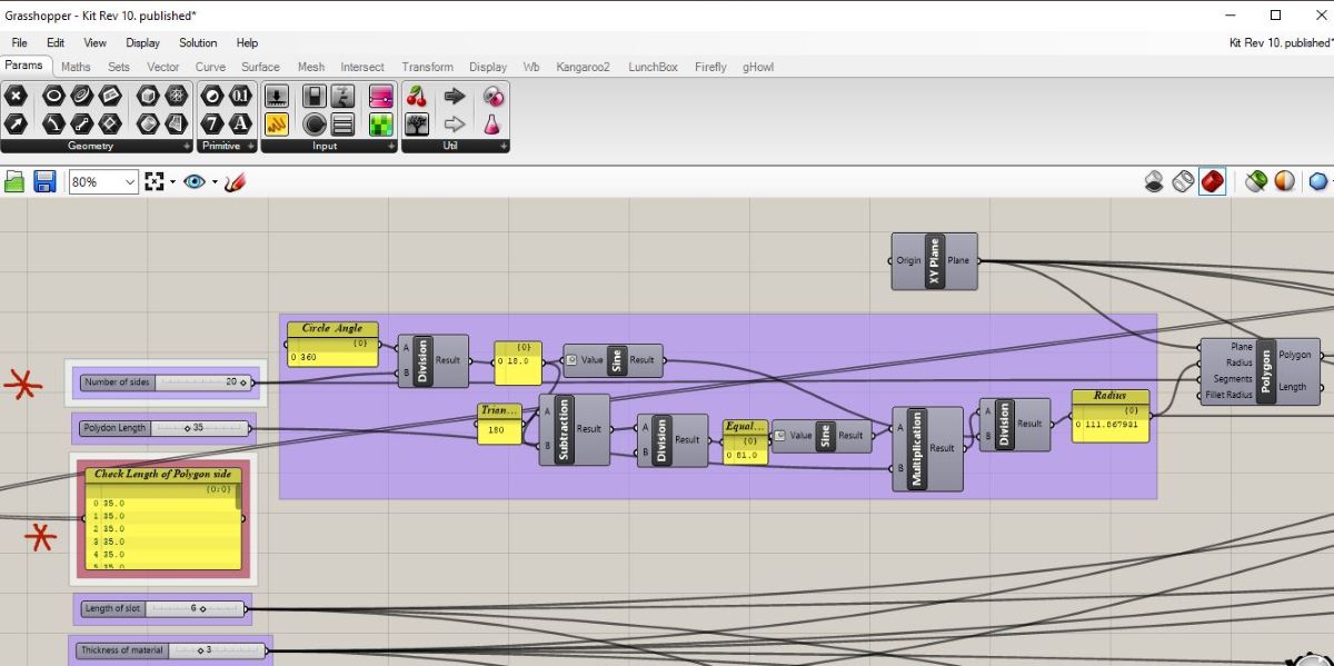
Acutely, Javier’s logic in Grasshopper helps me to start in… I made the press-fit parts like him. The way to draw the rectangle perpendicular on a line. The other steps are very easy … if you need to understand how I draw it, you can download the file and hide all the component then preview one by one. Also, I documented Last week some notes about using Grasshopper for the first time and explained the whole process to make an example, So I think the file is very easy to be read.

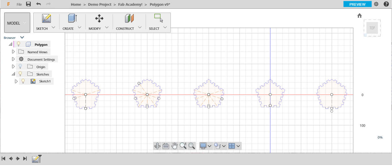
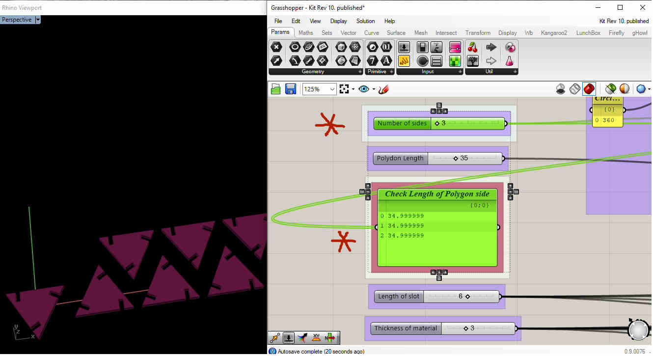
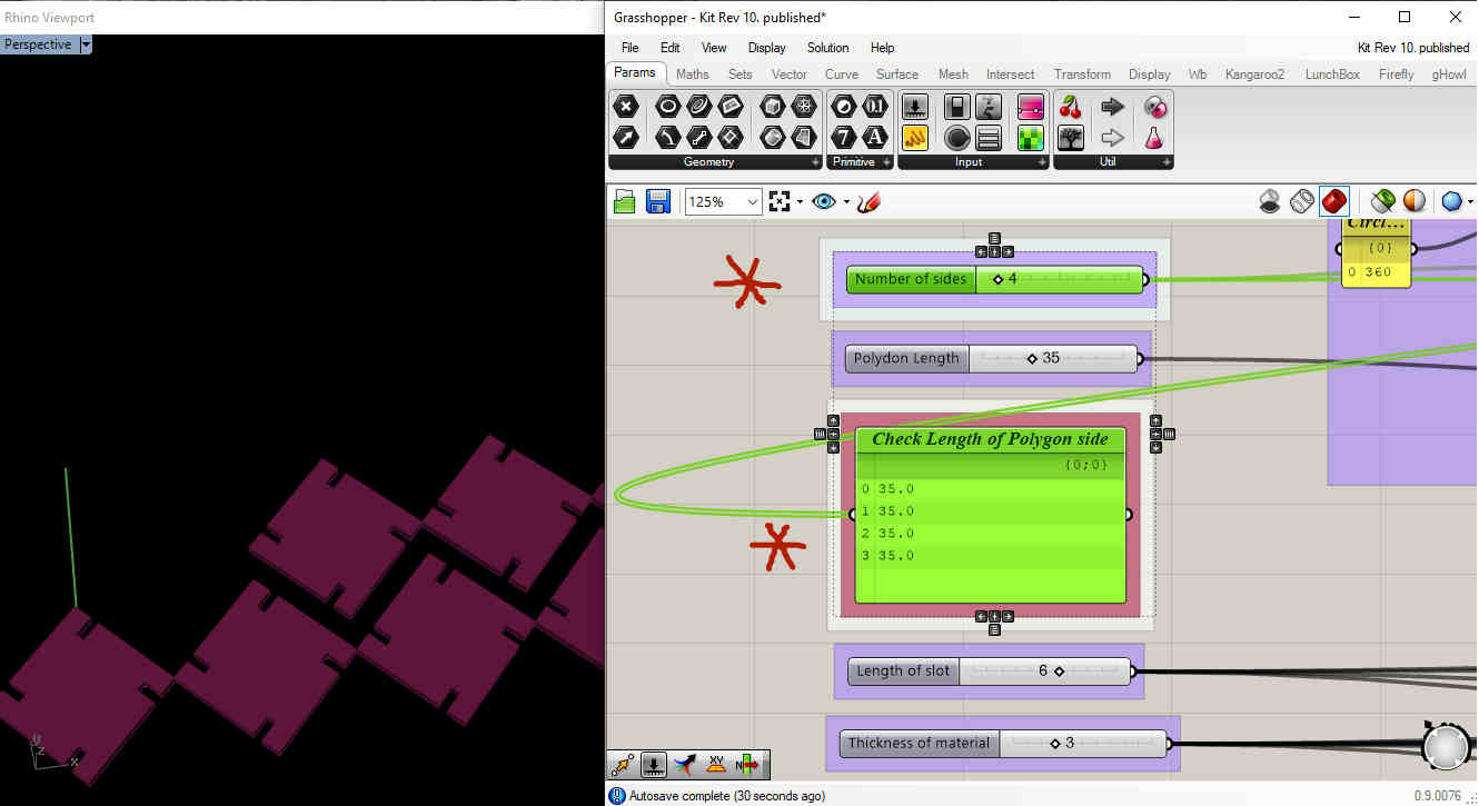
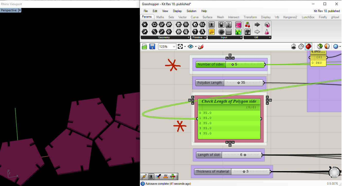
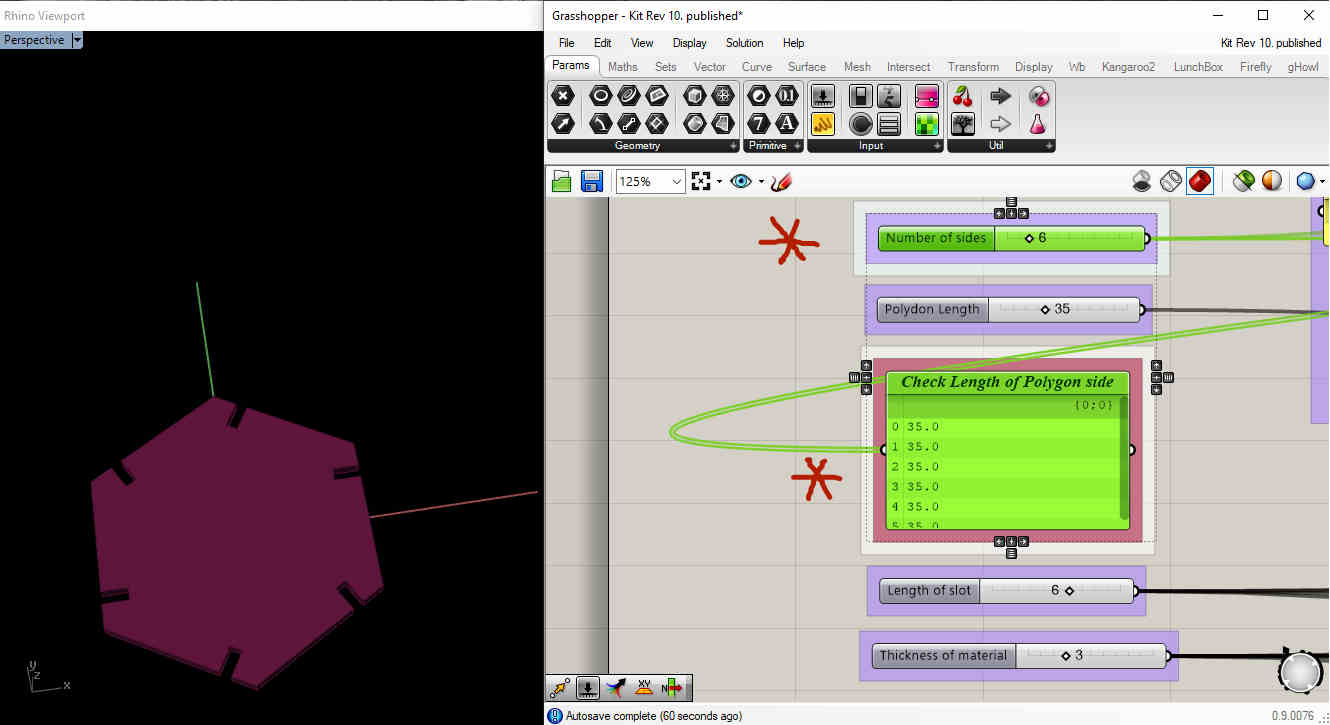
- We notice that when the sides of the polygon are 3 the length side almost equal 52

- When the sides of the polygon are 4 the length side almost equal 43
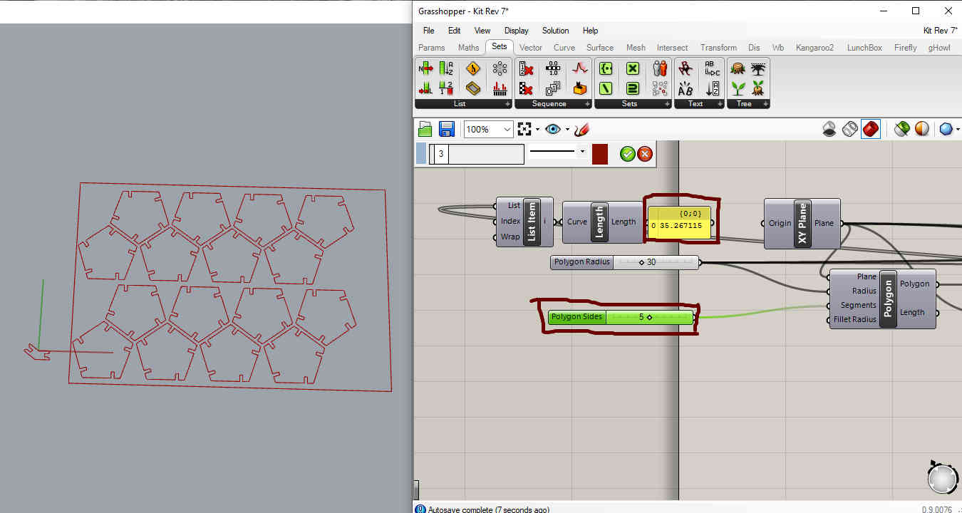
- When the sides of the polygon are 5 the length side almost equal 35
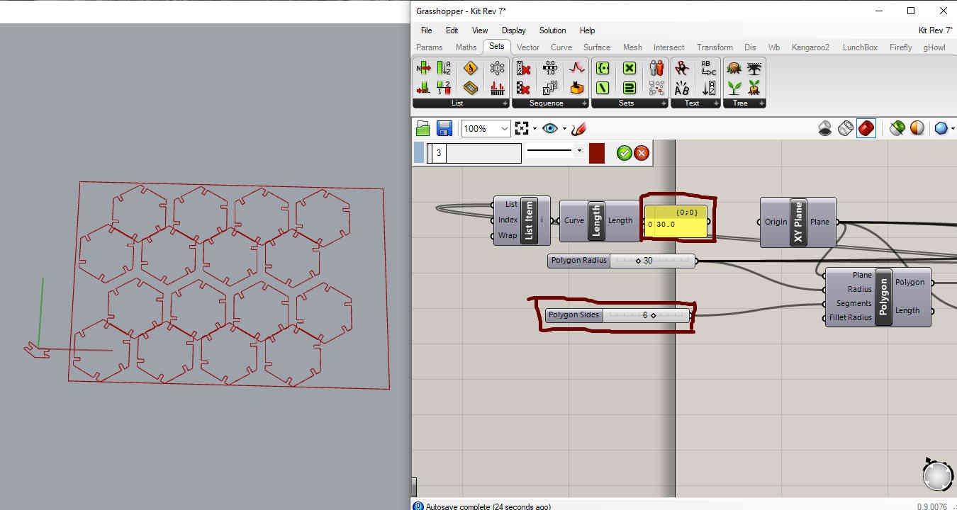
- When the sides of the polygon are 6 the length side almost equal 30
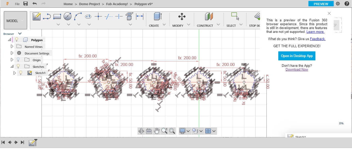
This is my second time to fault at this point!
It’s supposed that it’s parametric shape, so we need to change the sides of the polygon from three, four, five … and else. But when we put all polygons together we need the length of the sides is the same…But these previous images don’t explain that…
This is the point of the Geodesic Ball Geometry…
For this point … my kit not parametric … That because we draw the polygon based on a constant radius of circle…
So I start to think again at this point …
All that I need to make a constant length ‘sides of the polygon’. but the polygon change based on the angle faced this side, and repeat these sides to close the circle with 360 degree
Adham A. Hammoda, ‘He’s smart in math plus piano’, he sent me this equation
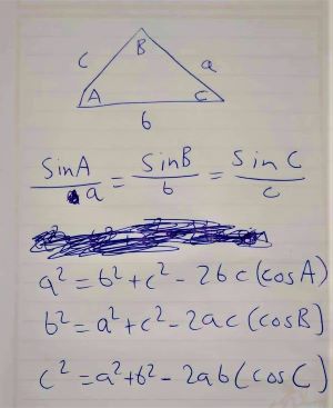
Also, This link explains what I mean.
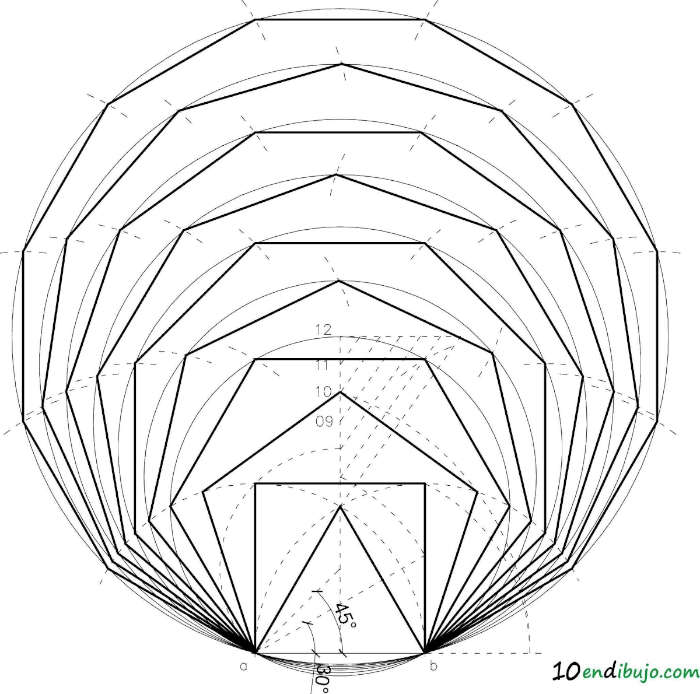
From here I start to redesign my kit
This is the true equation…
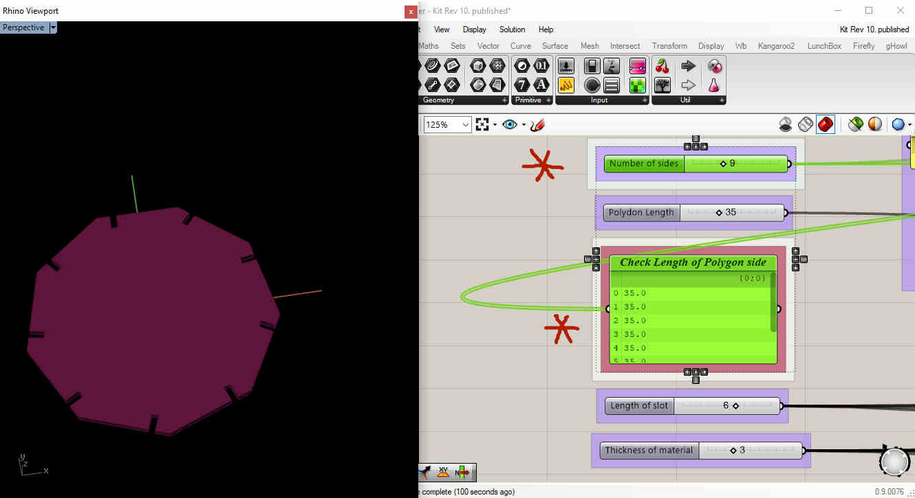
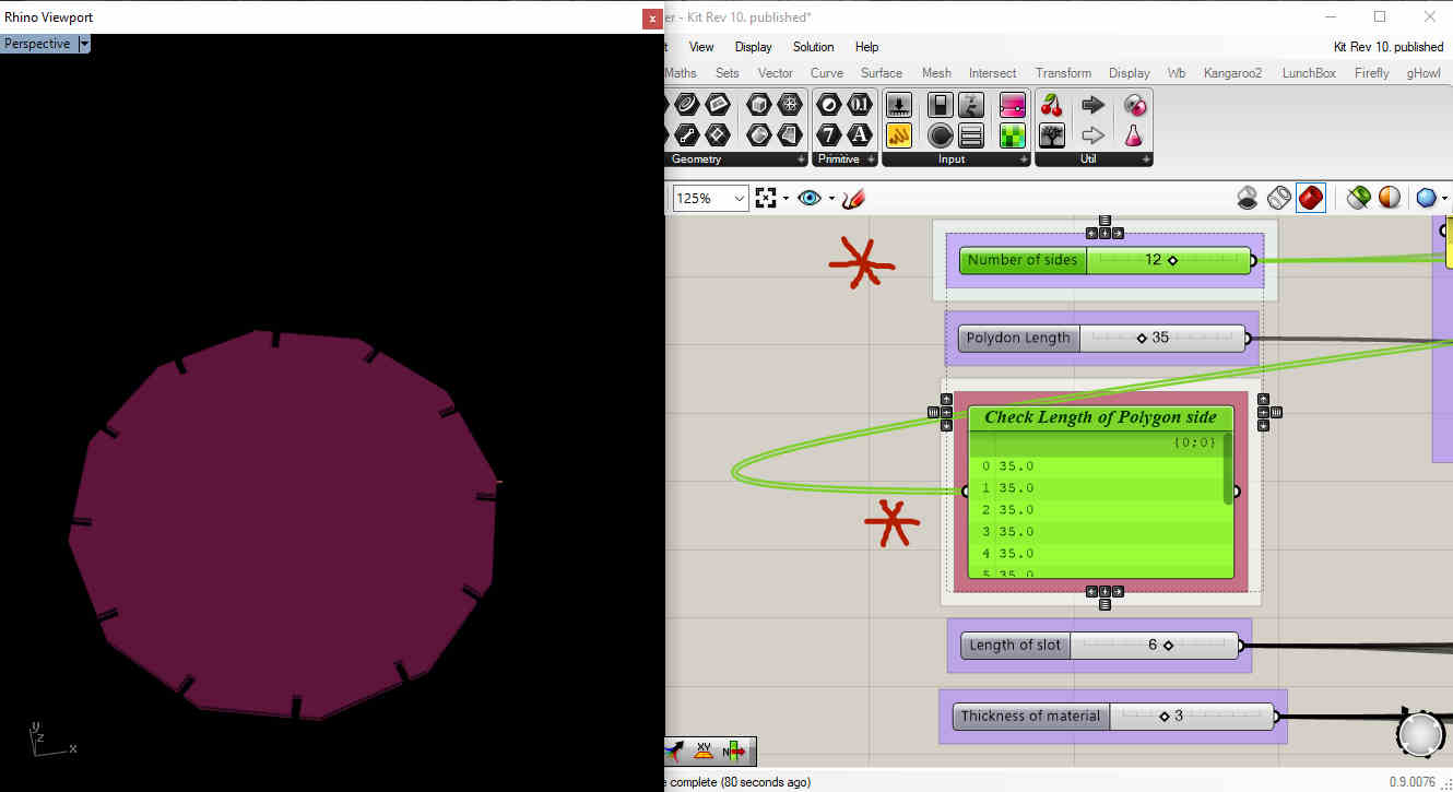
We notice that all polygons have the same length as the side…
So my parts are ready Now!
Feel Free to Download the Files
-
Fusion360
-
Rhinoceros .3dm
-
Grasshopper
Vinyl
References
-
Ohad Meyuhas, ‘Our inspiring guru’ recommended some important links before our week assignment, they are very useful
- The Secret to Mastering Transfer Tape
- LAYERING MULTICOLORED VINYL DECALS WITH CRICUT EXPLORE | REGISTRATION MARKS
Acutely these videos inspired me to get a good concept
concept
For this point, I have an idea… I thought what if I continue in the laser cutter Dodecahedron.kit3 that I have been designed and make geometry with the base and the secondary colors, to learn them the both’ Geometry shape and colors’
So I start with freehand sketch ‘Unfortunately I lost the sketch’ for my idea and started to divide the colors into the sides… my geometry is Dodecahedron

By User Cyp on en.wikipedia - transferred from en.wikipedia, see w:en:Image:Tetrakishexahedron.gif for source., CC BY-SA 3.0, Link
that includes 12 sides … So my concept to make
- Three sides with the primary colors ‘red, yellow and blue’
- Three sides with secondary colors ‘green, orange and purple’
- Then we have another six sides … three of them, one will include two primary colors and the mixed color ‘red + blue = purple’ .... and so on
- Last three sides for mixed all colors with different shapes.
Before starting in my designs I checked the available colors.
Design Process
- I used Inkscape software to make raster design. This is my first time to use this software that Haggag recommended for us. So he recommended
Inkscape tutorials
that made in the Maker Diploma Program, it’s very easy to learn. So I started in.
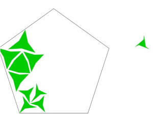
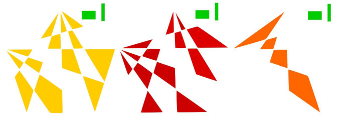
- This is the first design I started in … My base shape in the right … then I controlled in the corner points and scale, rotate … to make different sizes and shapes
while this stage I didn’t convince to make a parametric shape without a parametric tool!
So, I decided to not continue in this one…
Polygon 1
- Then, I designed these shapes… after finished, I didn’t like it!
Polygon 2
- So, this is the last design… for one side
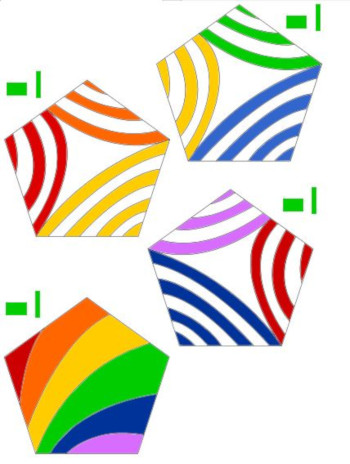
Polygon 3
- This is for the three sides that include the primary colors and mixed colors
I made it as I learned from the videos … with reference sign in every color.
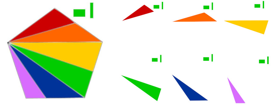
Polygon 4

Split the reference with the main color
Now, my images are ready to the next step!
Vinyl Cutter
Technical Process
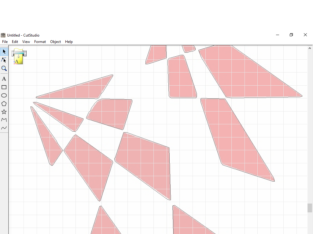
I used cutstudio software, that
- import our PNG
- create outlines for our design
- generate the tool path to the vinyl
- Make self-test to the machine … that an incredible test that vinyl makes to set all parameters from speed, cut depth … to choose the default case.
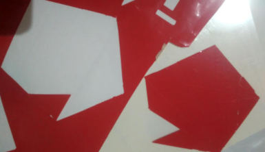
I opened my first image, using the red sheet roll
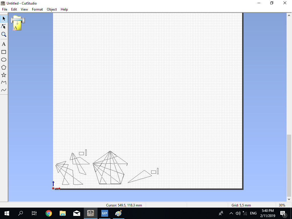
I noticed here, something wrong with the pixels. I don’t know the reason. But I continue!
![]()
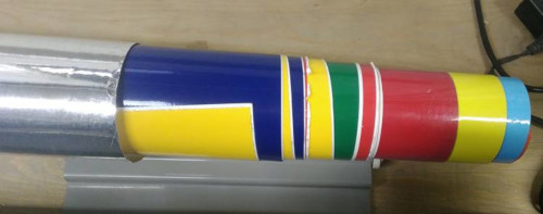
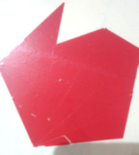
So this is the result
Get your design
I have taken some times to imagine the process of vinyl and why we do that!
We put scotch in the product design from vinyl… to remove our design and transfer it to the right place that we want. Finally, I convinced this is the only way for this process…
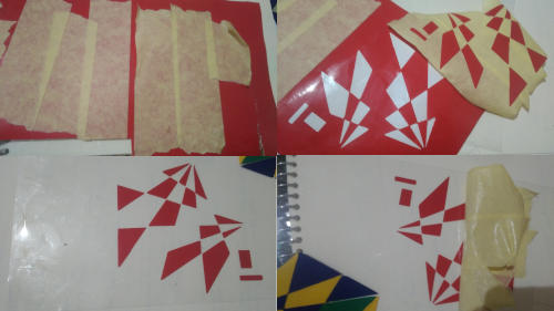
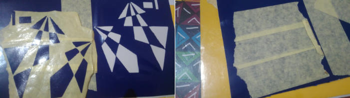
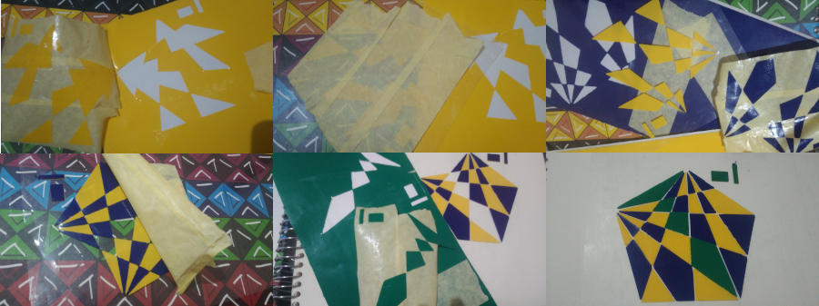
So my start point here
- Put the scotch on my designs, and make sure it fixed well
- Transfer the scotch includes the only parts that we want
- Pick it in the right place
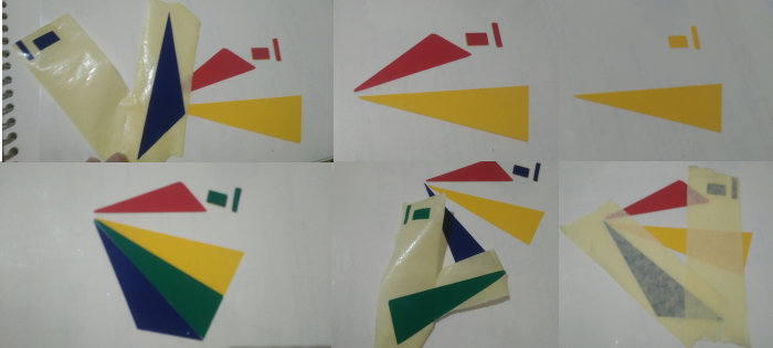
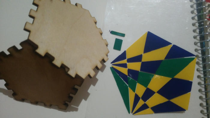
- For my case … I have to put my different colors refer to the reference sign that I made
For here I found the colors that I wanted not for vinyl cutter … It’s disappointing that I wouldn’t complete my concept… but Let’s continue
Feel Free to Download the Files
See You!!