8. Computer controlled machining
make something big
Visit Group website for more imformations. Click here.
CNC
CNC Machining is a process used in the manufacturing sector that involves the use of computers to control machine tools. Tools that can be controlled in this manner include lathes, mills, routers and grinders. The CNC in CNC Machining stands for Computer Numerical Control. On the surface, it may look like a normal PC controls the machines, but the computer’s unique software and control console are what really sets the system apart for use in CNC machining.
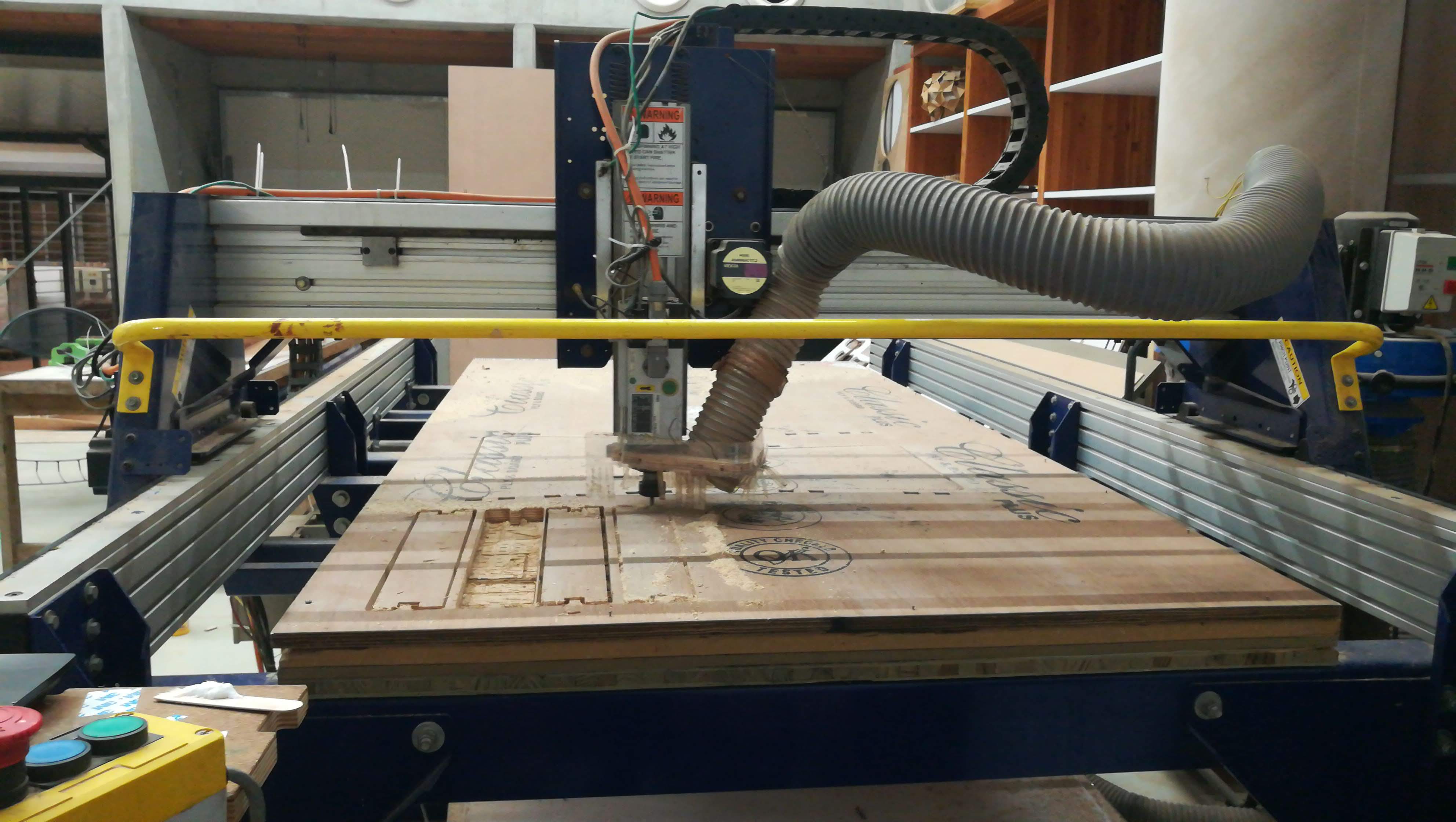
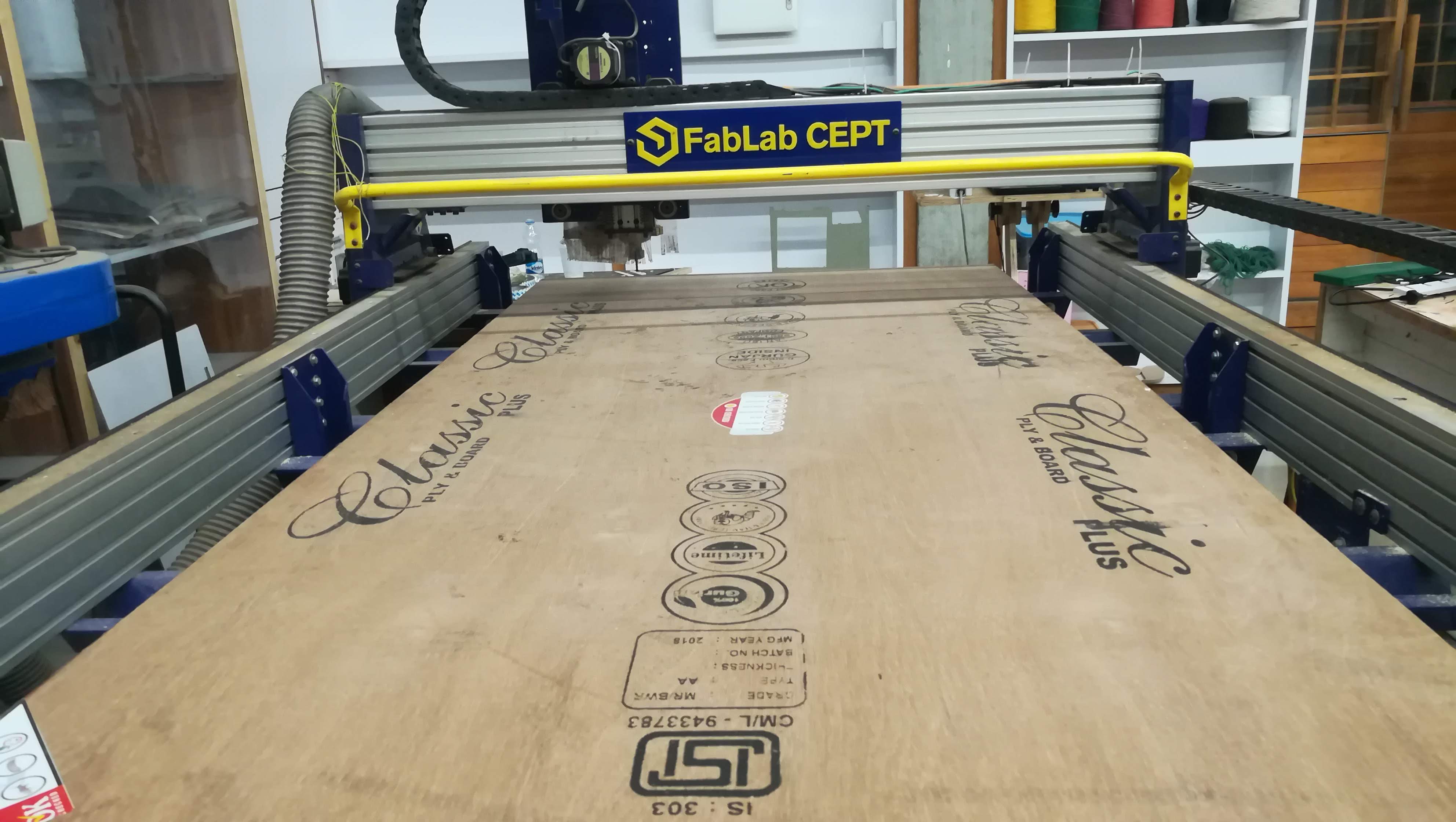
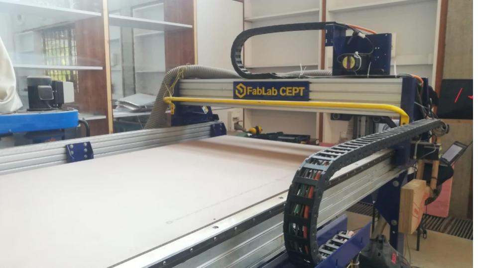 Our Shopbot
Under CNC Machining, machine tools function through numerical control. A computer program is customized for an object and the machines are programmed with CNC machining language (called G-code) that essentially controls all features like feed rate, coordination, location and speeds. With CNC machining, the computer can control exact positioning and velocity. CNC machining is used in manufacturing both metal and plastic parts.
First a CAD drawing is created (either 2D or 3D), and then a code is created that the CNC machine will understand. The program is loaded and finally an operator runs a test of the program to ensure there are no problems. This trial run is referred to as “cutting air” and it is an important step because any mistake with speed and tool position could result in a scraped part or a damaged machine.
There are many advantages to using CNC Machining. The process is more precise than manual machining, and can be repeated in exactly the same manner over and over again. Because of the precision possible with CNC Machining, this process can produce complex shapes that would be almost impossible to achieve with manual machining. CNC Machining is used in the production of many complex three-dimensional shapes. It is because of these qualities that CNC Machining is used in jobs that need a high level of precision or very repetitive tasks.
It would be useful to have a background in mathematics, industrial arts and mechanical drafting, as well as computer usage.
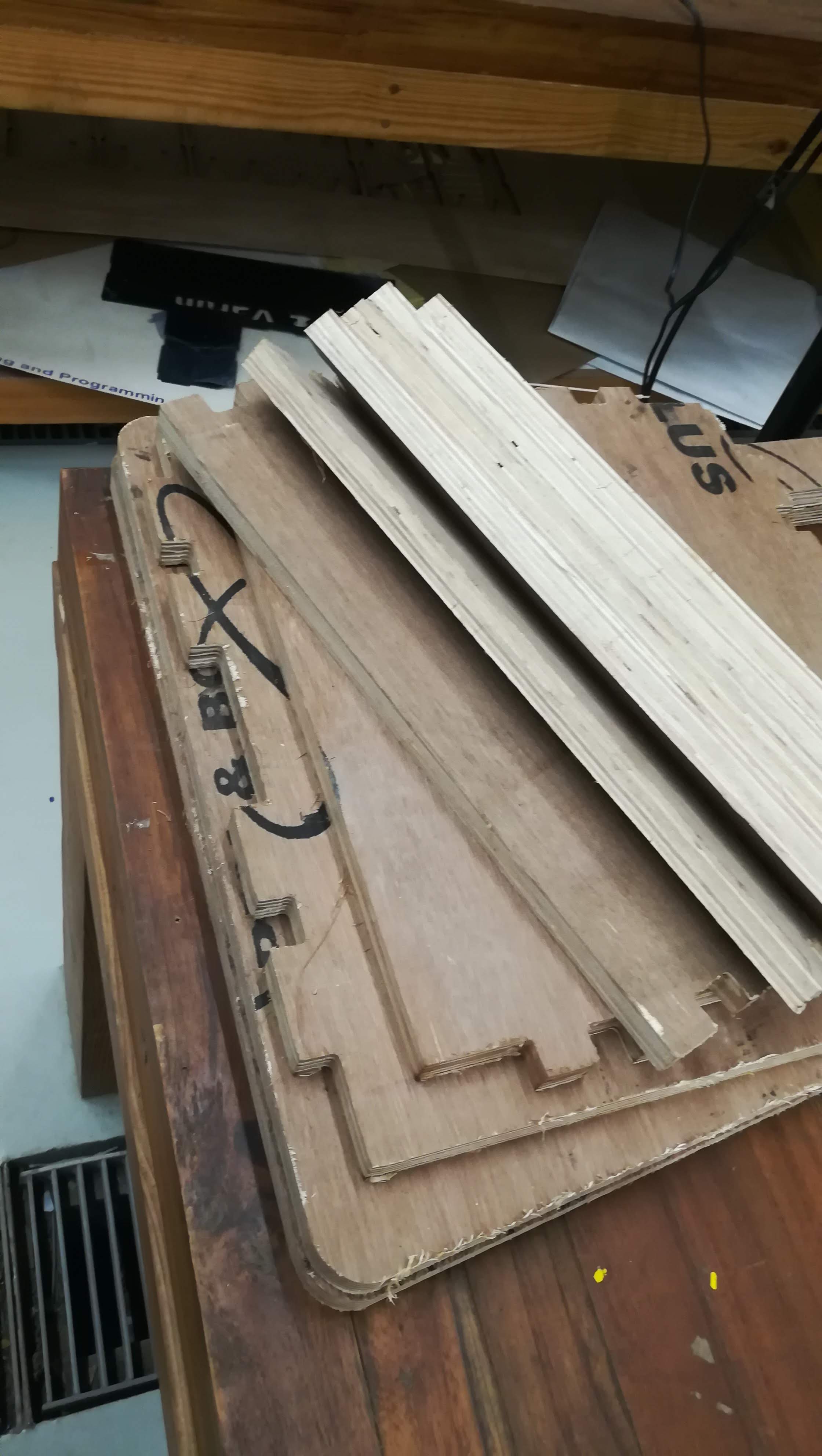
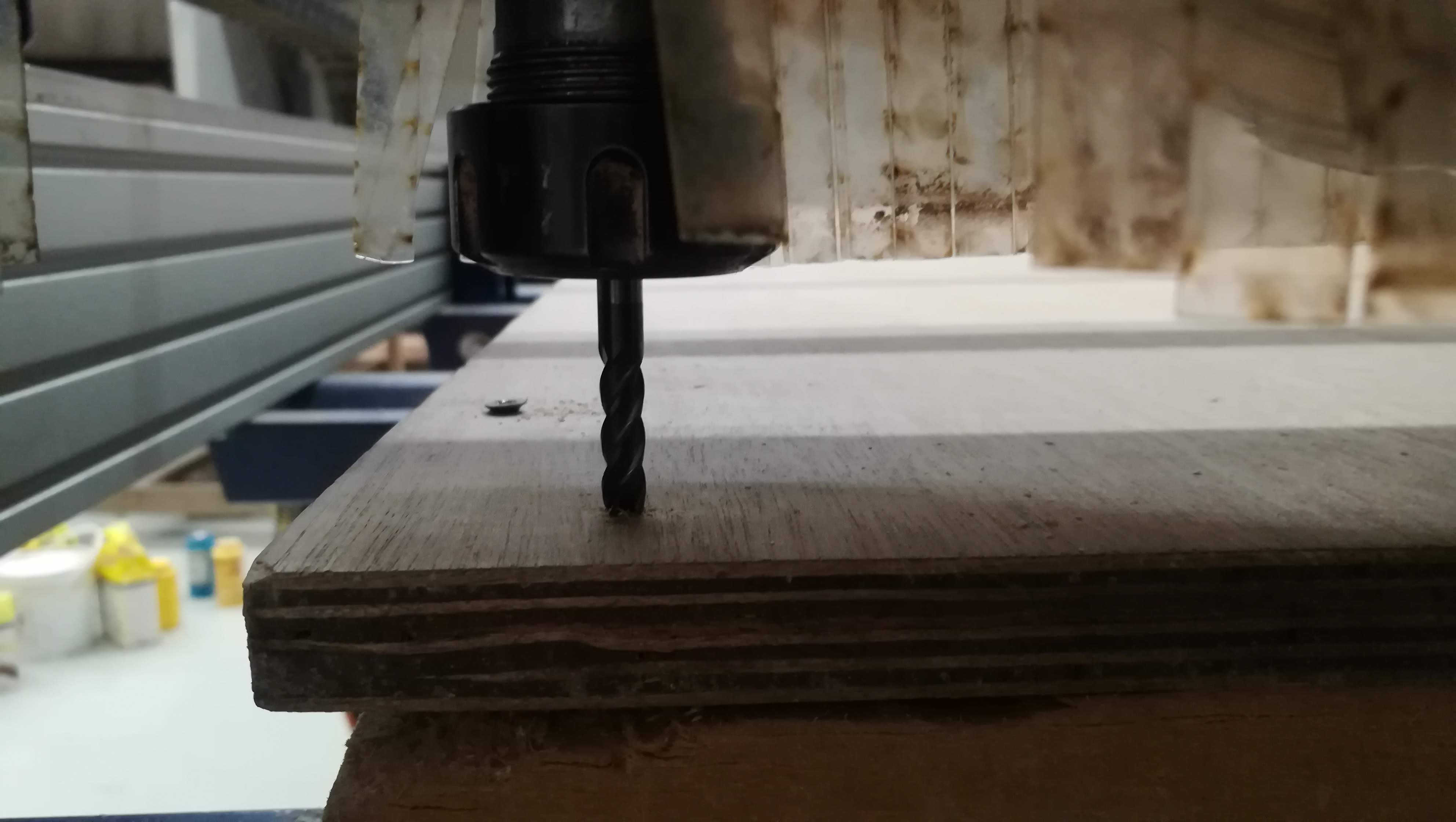
Sacrificial Layer - x
Shopbot machines bed made up of metal and to protect this bed we have to place flat layer of the plywood on the metal bed which is the sacrificial layer. In case the endmills plunges more than the thickness of the material it will cut into the sacrificial layer, so for this Sacrificial layer is important. While cutting our main part is placed over the sacrificial layer and clamp it.
Overview of CNC Milling Process
- Designing a CAD model
- Converting the CAD model into a CNC program
- Setting up the CNC milling machine
- Executing the milling operation
Outlines
- feed rate,
- coordination,
- location
- speeds
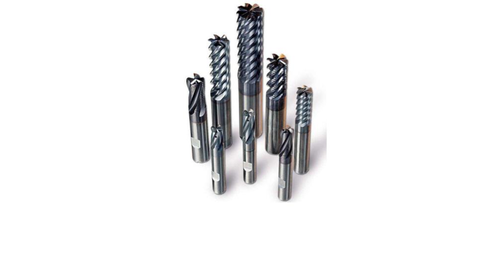
End Mill
End mills are tools which have cutting teeth at one end, as well as on the sides, they are used for a variety of things including facing an edge, and cutting slots or channels. There are many types of End Mills to choose from, and with each style there are a variety of materials including High-Speed Steel, Cobalt Steel and Carbide. There are also many options for how many flutes there are ranging from 2 to 8 normally. Lastly, for each style there are roughing and finishing end mills.
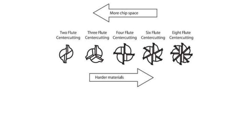
Flute Diagram
This is a flute diagram. It shows what a two flute, three flute, four flute, six flute, and eight flute mill end looks like from the bottom. Then, the arrows show that you want to go to the right when cutting a harder material and cut to the left to take off more chips.
What’s a Router?
Before discussing or using a CNC router it is helpful to know how to use a handheld router. Your typical router has a motor (possibly a variable speed motor), height adjustment (either fixed, or plunge), and a collet, which is a tapered spring that when compressed creates the friction necessary to hold your cutting tool in place.
What are Toolpaths?
A toolpath is the user-defined coded route which a cutting tool follows to machine a part. They are represented on the screen by lines and curves which represent the path of the bottom center of the cutting tool. Pocket toolpaths etch the surface of the material, while profile toolpaths cut all the way through.
Pocket
The process described in the handheld example above is called a “pocket” toolpath. In your first pass you will remove everything inside your lines to a constant depth of 1/8 inch below the surface. If you want to remove more than 1/8 of an inch simply pause after the first pass, lower the bit, and remove a second pass 1/8 of an inch lower and so on.
Profile
If you were to want to cut out your shape instead of removing material inside the lines, the toolpath to use would be called a profile (or contour).
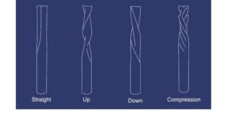
Tooling
There are 4 main types of flute patterns for router bits, plus many types of specialty bits.
Types of bits Straight Flute – great all around bit, decent chip removal Up Spiral – great chip removal, can tear-out the top of thin veneer such as finish grade plywood Down Spiral – poor chip removal, no tear out, slower feed rate Compression – combination of up and down spiral, great all around bit, great for plywood or laminated sheet goods.
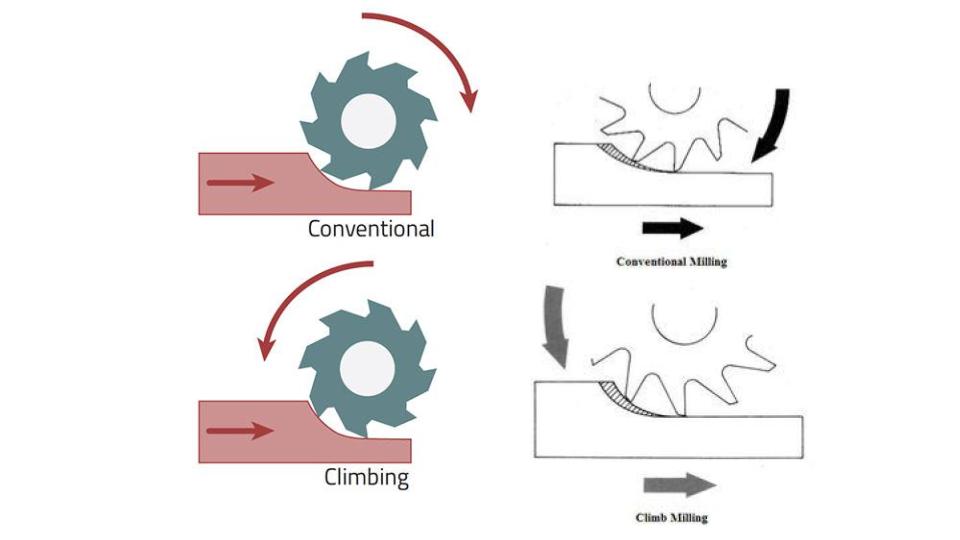
Climb vs. Conventional Cutting Motion
A standard router bit spins clockwise. If this were to follow the left side of the line it would be a climb cut, if it were to follow the right side of the line it would be a conventional cutting motion.
Feeds and Speeds (Source Click Here)
Most spindles (the term for the router attached to your cnc router) will go from about 7,000rpm to 18,000rpm. This speed is termed ‘spindle speed’ and is directly related to the feed rate or surface speed, which most machines are capable of doing up to about 200pm. The two other variables, step-down and step-over should be kept so that the cross-sectional area engaged with the material is no more than the radius times the diameter of the bit. This is a rule of thumb, but it’s a good starting point for feed and speed calculations.
To recap:
Spindle Speed – rotational speed of the cutting tool in revolutions per min
Feed Rate – Surface speed at the center of the rotating tool
Step down – the distance in the z direction per pass that a cutting tool is plunged into the material
Step over – the maximum distance in the x/y direction that a cutting tool will engage with uncut material
FEED IN INCHES PER MINUTE (IPM) OR (F)
- Modern milling cutters capable of operating at higher feeds and speeds, and removing more cubic inches of metal per minute, require greater machine rigidity and more power. Therefore it is important to ascertain that sufficient power is available to handle the desired depth and width of cut at the higher feeds and speeds.
Approximation
The exact RPM is not always needed, a close approximation will work (using 3 for the value of ).


e.g. for a cutting speed of 100 ft/min (a plain HSS steel cutter on mild steel) and diameter of 10 inches (the cutter or the work piece)

and, for an example using metric values, where the cutting speed is 30 m/min and a diameter of 10 mm (0.01 m),

Accuracy
However, for more accurate calculations, and at the expense of simplicity, this formula can be used:

and using the same example

and using the same example as above

where:
- RPM is the rotational speed of the cutter or workpiece.
- Speed is the recommended cutting speed of the material in meters/minute or feet/min
- Diameter in millimeters or inches.
Feed rate
Feed rate is the velocity at which the cutter is fed, that is, advanced against the workpiece. It is expressed in units of distance per revolution for turning and boring (typically inches per revolution [ipr] or millimeters per revolution). It can be expressed thus for milling also, but it is often expressed in units of distance per time for milling (typically inches per minute [ipm] or millimeters per minute), with considerations of how many teeth (or flutes) the cutter has then determined what that means for each tooth.
Feed rate is dependent on the:
- Type of tool (a small drill or a large drill, high speed or carbide, a boxtool or recess, a thin form tool or wide form tool, a slide knurl or a turret straddle knurl).
- Surface finish desired.
- Power available at the spindle (to prevent stalling of the cutter or workpiece).
- Rigidity of the machine and tooling setup (ability to withstand vibration or chatter).
- Strength of the workpiece (high feed rates will collapse thin wall tubing)
- Characteristics of the material being cut, chip flow depends on material type and feed rate. The ideal chip shape is small and breaks free early, carrying heat away from the tool and work.
- Threads per inch (TPI) for taps, die heads and threading tools.
- Cut Width. Any time the width of cut is less than half the diameter, a geometric phenomenon called Chip Thinning reduces the actual chipload. Feedrates need to be increased to offset the effects of chip thinning, both for productivity and to avoid rubbing which reduces tool life.
When deciding what feed rate to use for a certain cutting operation, the calculation is fairly straightforward for single-point cutting tools, because all of the cutting work is done at one point (done by "one tooth", as it were). With a milling machine or jointer, where multi-tipped/multi-fluted cutting tools are involved, then the desired feed rate becomes dependent on the number of teeth on the cutter, as well as the desired amount of material per tooth to cut (expressed as chip load). The greater the number of cutting edges, the higher the feed rate permissible: for a cutting edge to work efficiently it must remove sufficient material to cut rather than rub; it also must do its fair share of work.
The ratio of the spindle speed and the feed rate controls how aggressive the cut is, and the nature of the swarf formed.
Formula to determine feed rate
This formula can be used to figure out the feed rate that the cutter travels into or around the work. This would apply to cutters on a milling machine, drill press and a number of other machine tools. This is not to be used on the lathe for turning operations, as the feed rate on a lathe is given as feed per revolution.

Where:
- FR = the calculated feed rate in inches per minute or mm per minute.
- RPM = is the calculated speed for the cutter.
- T = Number of teeth on the cutter.
- CL = The chip load or feed per tooth. This is the size of chip that each tooth of the cutter takes.
Depth of cut
Cutting speed and feed rate come together with depth of cut to determine the material removal rate, which is the volume of workpiece material (metal, wood, plastic, etc.) that can be removed per time unit
Calculating Feeds and Speeds
Below is a formula for calculating feed rate:
ChipLoad x CutterDiameter x NumberOfFlutes x SpindleSpeed = FeedRate
If we plug in our known variables we get:
0.01 x 0.25 x 2 x 18000 = FeedRate = 90ipm
Keeping in mind that we don’t want to push the bit any faster than roughly 200ipm, if we wanted to use a 1/2 inch 4 flute bit, we could solve for spindle speed rather than feed rate.
0.01 x 0.5 x 4 x SpindleSpeed = 200ipm
SpindleSpeed = 10,000rpm
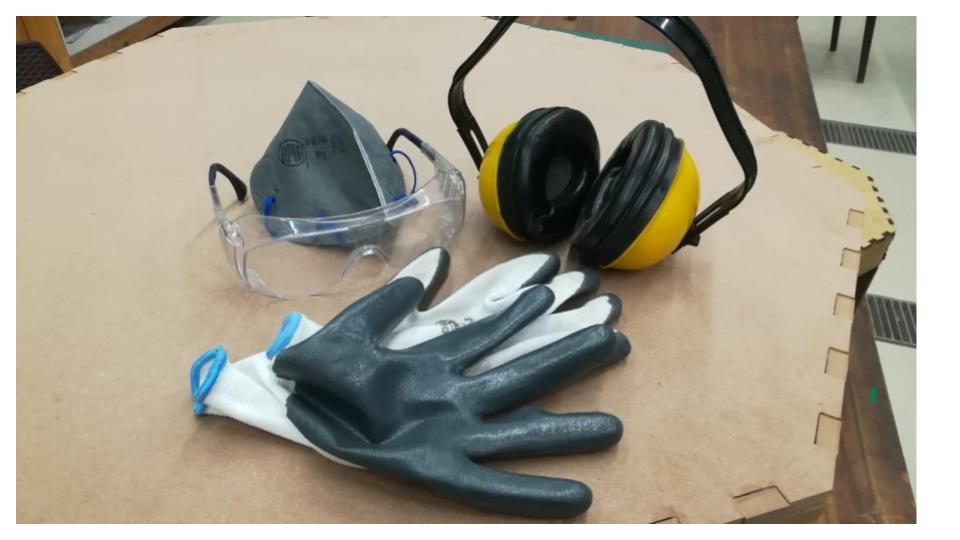
CNC Machine Safety
- An Emergency Stop Button
- A Soundproof Casing
- The Eye Guards
- Safety GLoves
DO:
- Always ensure that you wear proper ear protection and a good pair of safety glasses when operating a CNC machine.
- Ensure that your safety glasses are firmly in place every time you are closely observing the cutting tools.
- Ensure that you wear suitable footwear such as safety boots at all times.
- If you have long hair, ensure that you keep it covered when you operate the CNC machine.
- Keep your hands away from any moving parts during machining processes.
- Stand clear of the machine whenever it is operational. You should also warn any other people near the risk of being too close to it.
- Whenever you are handling or passing tools, avoid touching the cutting edges.
- Ensure that you turn the machine off completely and clean it whenever you have finished using it.
DON’TS:
- You should never wear jewelry or any loose clothing.
- You should never try to reach into the machine while it’s running
- You should never put your hands anywhere near the spindle when it’s revolving.
- Never leave the machine when it’s not completely powered down.
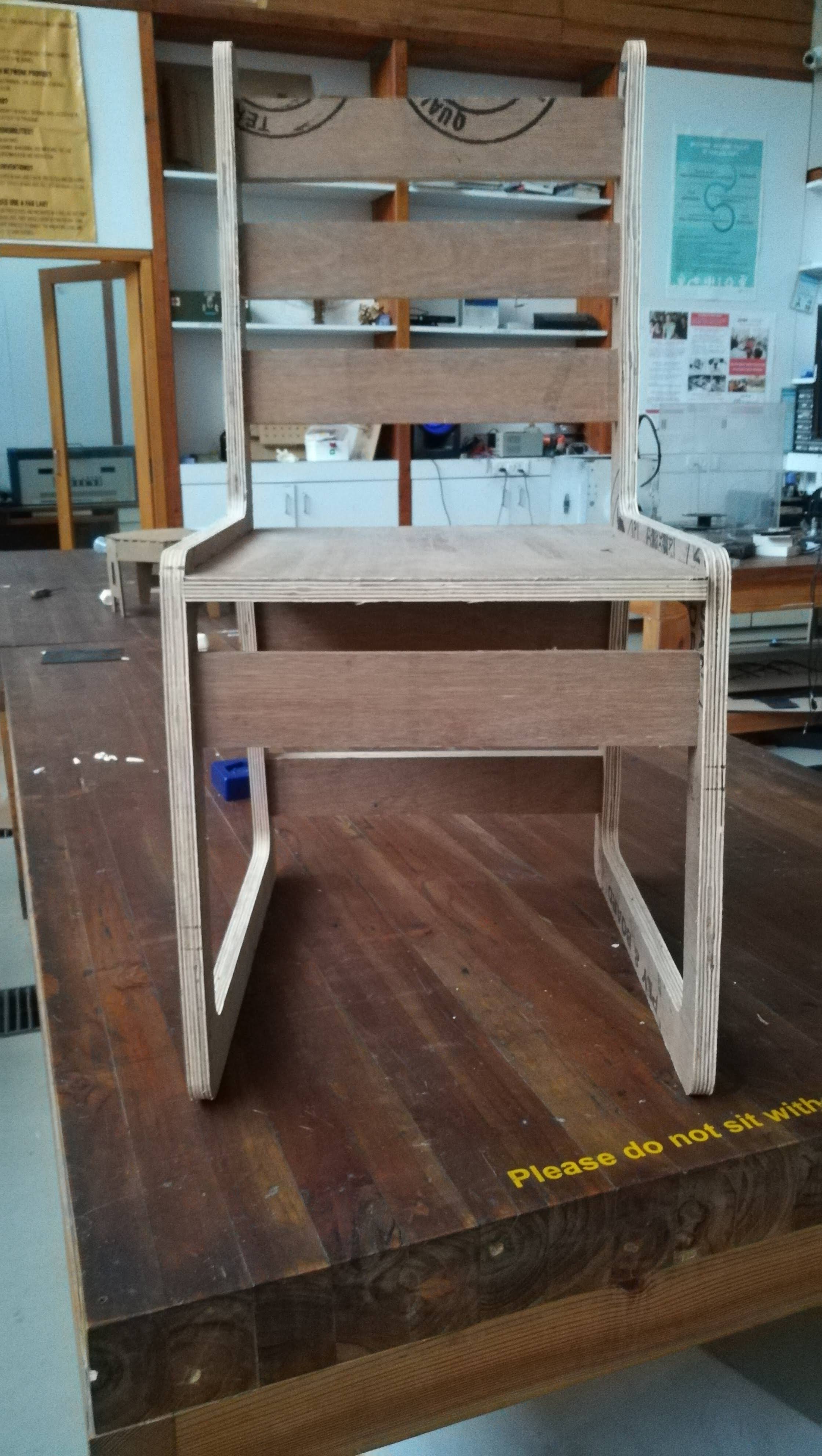
My Project for make something big
Chair
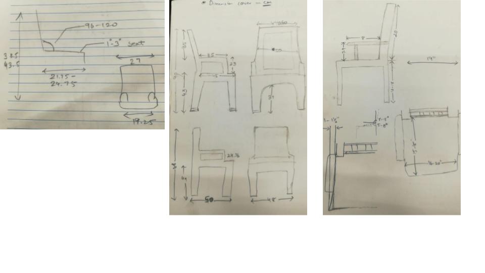
What is Ergonomics?
Ergonomics is the process of designing or arranging workplaces, products and systems so that they fit the people who use them. Most people have heard of ergonomics and think it is something to do with seating or with the design of car controls and instruments – and it is… but it is so much more.
Ergonomics applies to the design of anything that involves people – workspaces, sports and leisure, health and safety. Ergonomics aims to improve workspaces and environments to minimise risk of injury or harm.
So as technologies change, so too does the need to ensure that the tools we access for work, rest and play are/ designed for our body’s requirements.
Why is Ergonomics important?
Ergonomics aims to create safe, comfortable and productive workspaces by bringing human abilities and limitations into the design of a workspace, including the individual’s body size, strength, skill, speed, sensory abilities (vision, hearing), and even attitudes.
How does ergonomics work?
- Ergonomics is a relatively new branch of science, on research carried out in many other older, established scientific areas, such as engineering, physiology, and psychology.
- To achieve best practice design, Ergonomists use the data and techniques of several disciplines:
- anthropometry: body sizes, shapes; populations and variations
- biomechanics: muscles, levers, forces, strength
- environmental physics: noise, light, heat, cold, radiation,
- vibration body systems: hearing, vision, sensations
- applied psychology: skill, learning, errors, differences
- social psychology: groups, communication, learning, behaviours.
Software Intro:
-
In the starting of a week, I am designing about chair and table and start research about all the needed component or part
-
Now in a beginning of a week started with fusion 360 and starting designing different different types of chair working with different software like Rhino but there is some issue with my design then I started in auto care which is student license version here I started and new software AutoCAD for my chair design it is really awesome for some simple 2D features which is easily helping me to design my chair and it’s given me a better speed then fusion 360 and exporting as faster as then all software or else it also depends on my system.
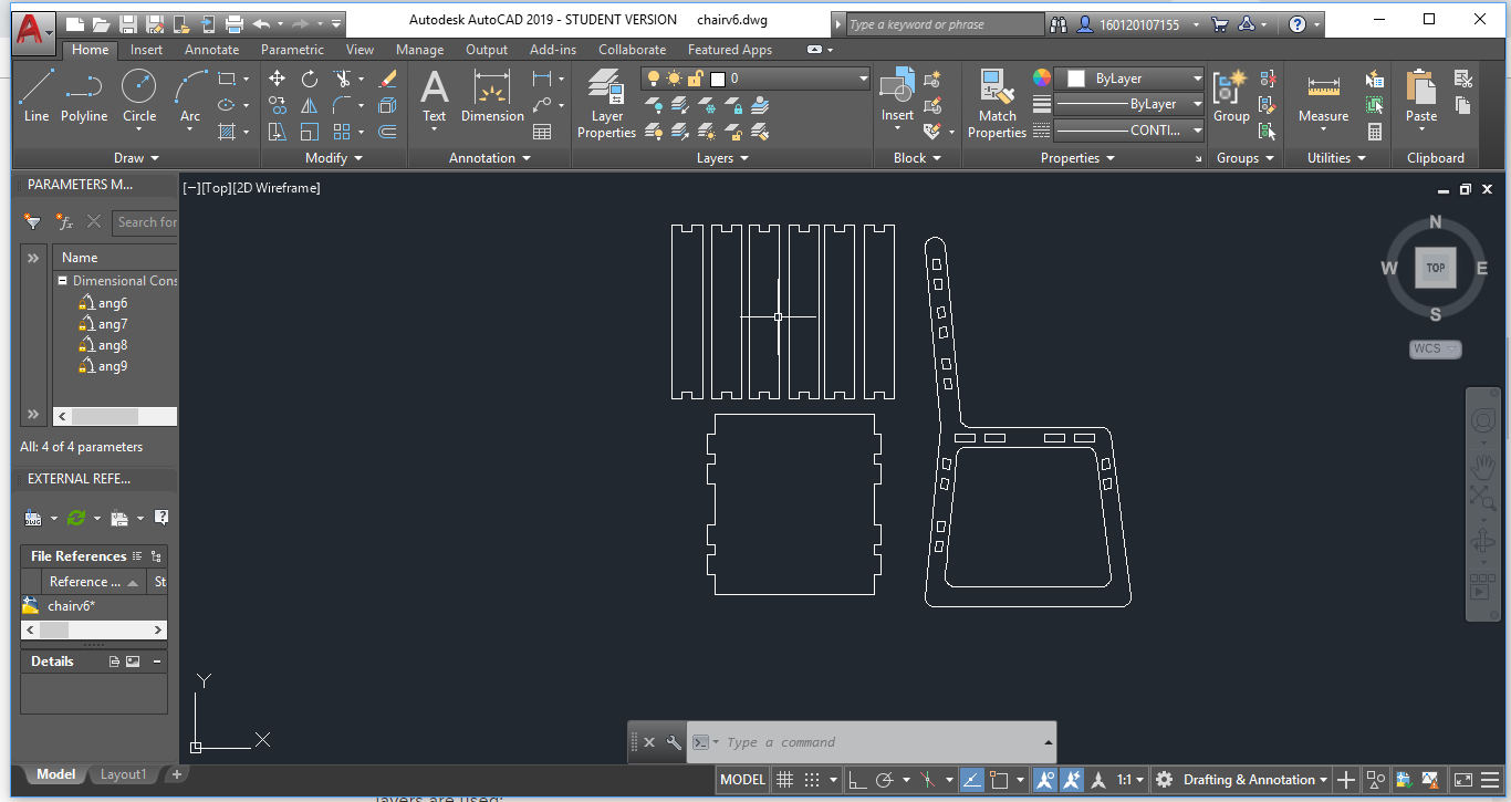
Afterward, I export to redesign and save it then it will be open in fusion 360 can I exclude as per my material and joining them at the end of that process I am reaching to my 3Dchair. - My Chair in 3d : https://a360.co/2RHTeiM
Explain how you image your files for machining (2D-3D)
In this week we hae “make something big” After sureying in regular life I got problem. Bacis of life we hae sit and work and my background is also from computer Engineering so i have to sit and work for long time.
So I decided to make chair. - One of the basic pieces of furniture, a chair is a type of seat. Its primary features are two pieces of a durable material, attached as back and seat to one another at a 90° or slightly greater angle, with usually the four corners of the horizontal seat attached in turn to four legs - Chair is based in strucure and Material from that how chair get look and is comforts for long time. - Now a part goes depends on Design and for design and we have to sit for long time so we need erogonomics property(Optional Part : ARMREST) - We hae to make sure about the all comforts. - Legs - Arms - backrest - Seat - Design considerations for chairs have been codified into standards. ISO 9241, “Ergonomic requirements for office work with visual display terminals (VDTs) – Part 5: Workstation layout and postural requirements”, is the most common one for modern chair design - Chairs may be rated by the length of time that they may be used comfortably – an 8-hour chair, a 24-hour chair, and so on. Such chairs are specified for tasks which require extended periods of sitting, such as for receptionists or supervisors of a control panel.


Dog Bone Filets - For CNC Joinery
-
Would it be possible to add a function for dog bone filets, either in the Model or CAM workspace?
-
I used to use another CAM package that allowed you to select different interior corner types when creating a profile cut tool path. I could select “bisect line” then have the tool automatically “push” into an interior corner by a set amount.
-
A dog-boning feature should be on CAM side of design, not Model. Changing to a different diameter tool, for instance, would require that all dog-bone features in Model be changed to accommodate new bit. Over-cutting (dog-boning) is an optional and automated process in most CAM packages, including cheap ones like CamBam. Implementing this feature on Model (CAD) side also assumes that the draftsman is also the CAM programmer and knows best how to achieve part.
What is CAM Package?
- CAM is a subsequent computer-aided process after computer-aided design (CAD) and sometimes computer-aided engineering (CAE), as the model generated in CAD and verified in CAE can be input into CAM software, which then controls the machine tool.
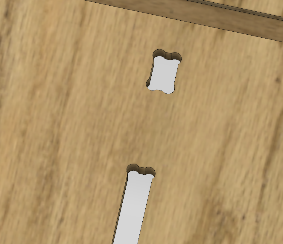
- This would save hours of design time creating these filets manually.
To create a drawing in Fusion 360:
- Open the Design you would like to create a 2D drawing of.
- Click the Workspace ribbon and hover over the “Drawing” option.
- New Drawing from Design creates a drawing of the design in the Model workspace.
-
New Drawing from Animation can help you leverage exploded views that you’ve created in the Animation Workspace.
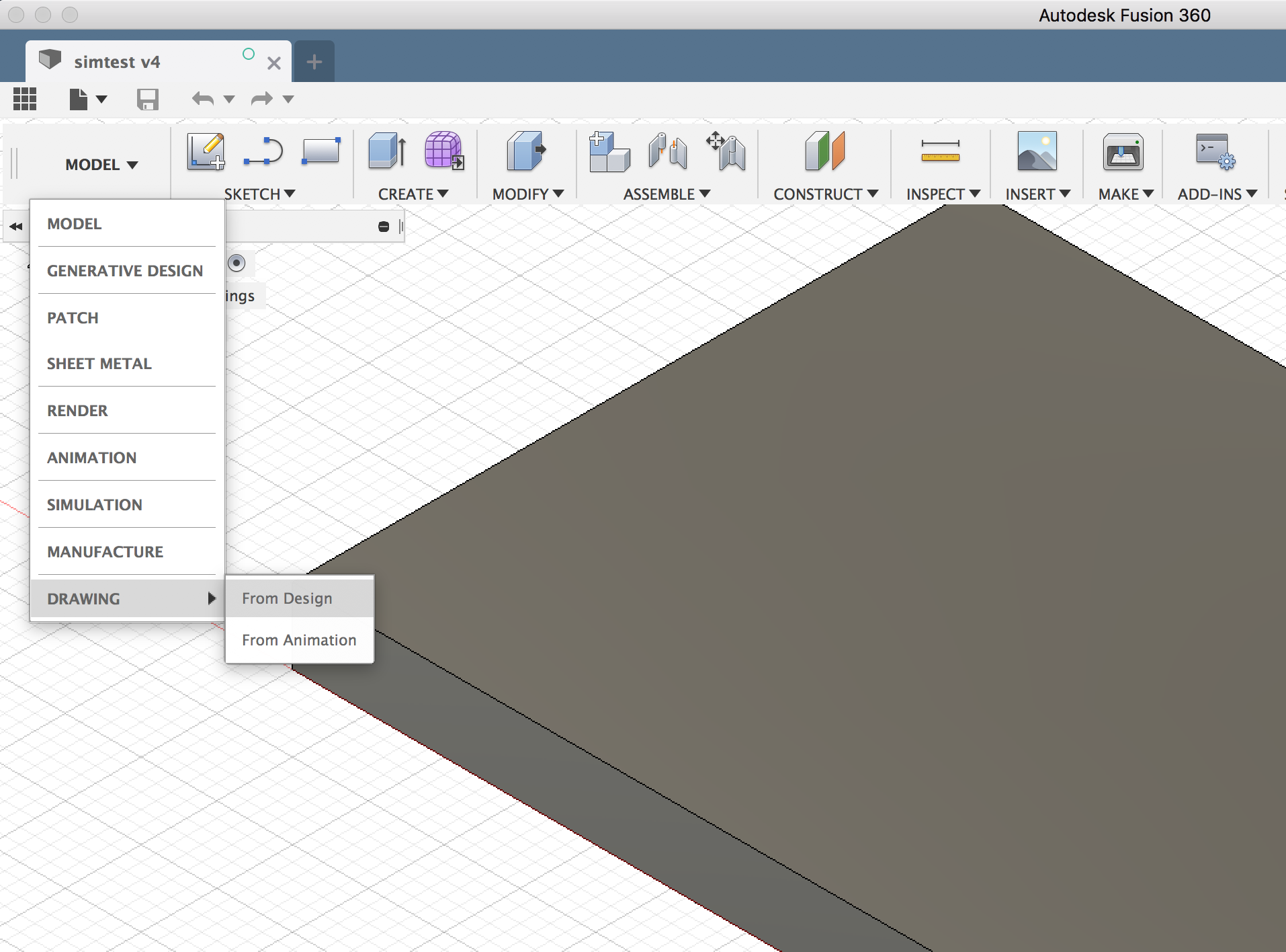
-
Select the desired options in the Create Drawing dialog box.
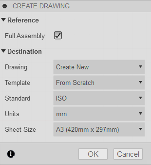
-
The “Full Assembly” box determines if the drawing will show the full assembly of the design the drawing is being created from.
Note: Unchecking the box will allow you to individually select the components or bodies from the design to be included in the new drawing file.
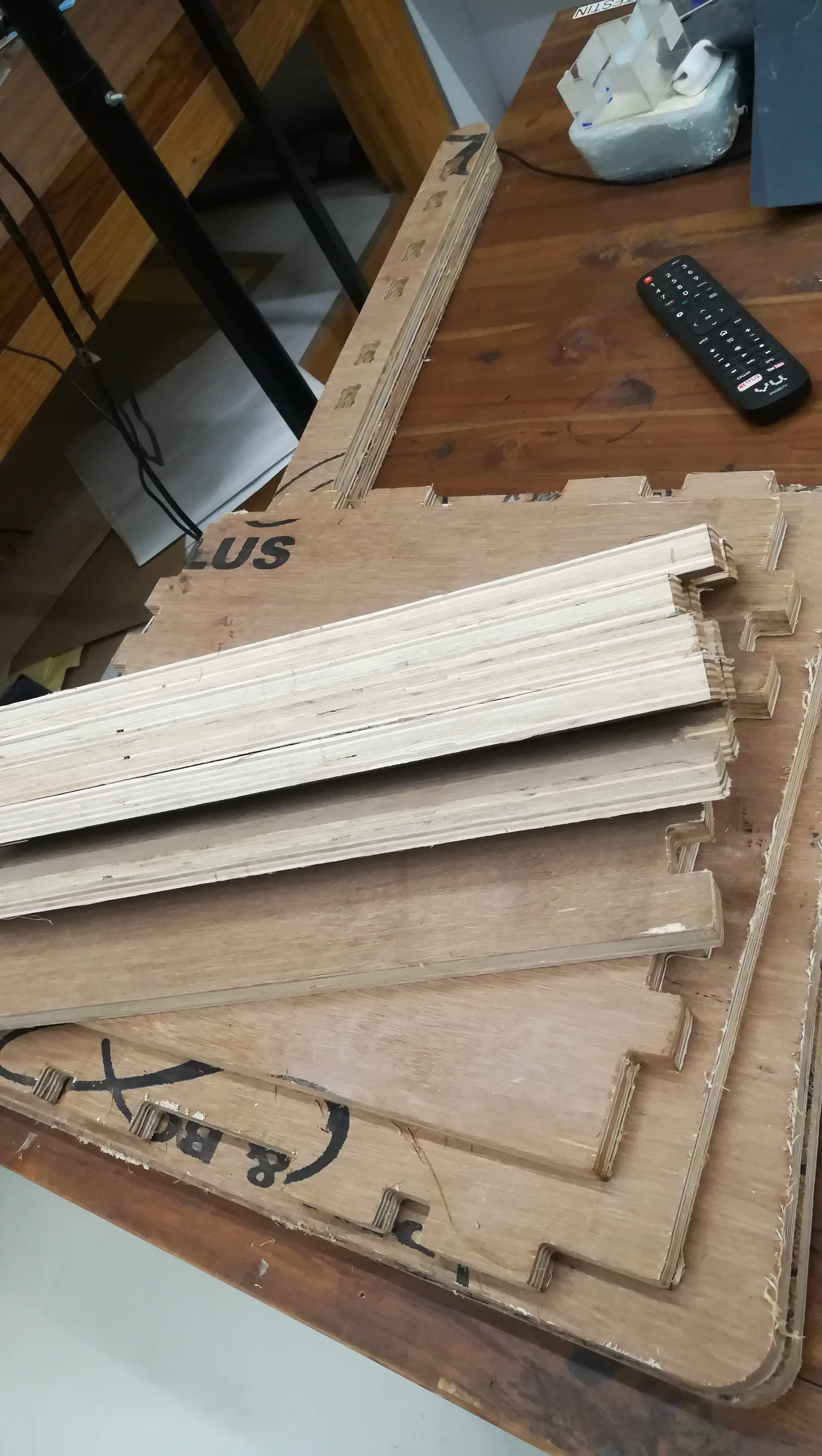
Process
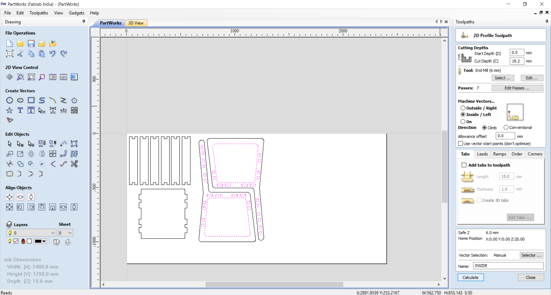
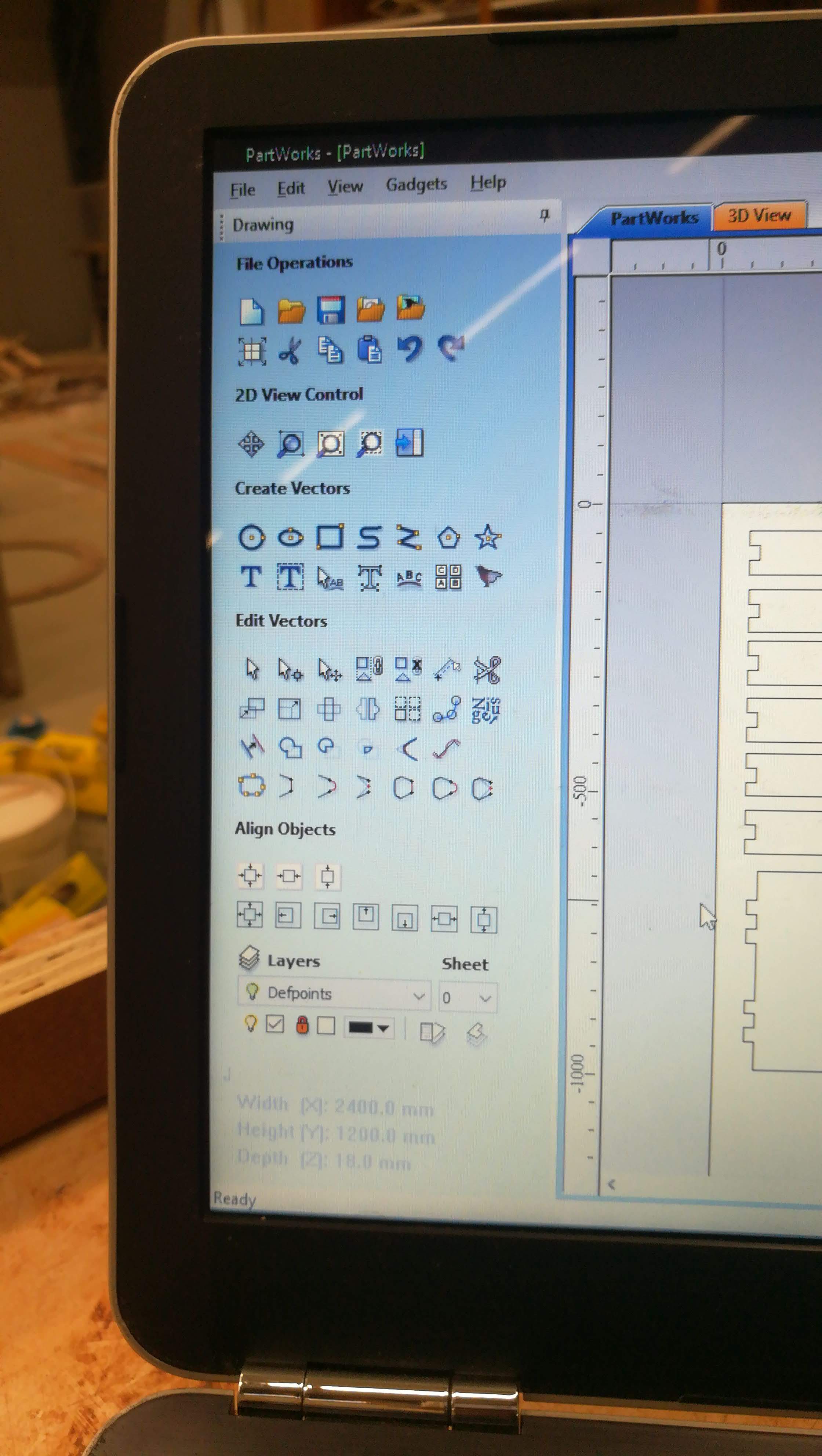
- Open part works and import .dxf file which is ready AutoCAD.
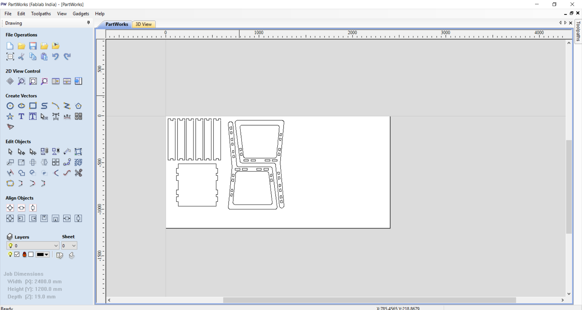
- For my CNC i am choosing 19mm Ply sheet.
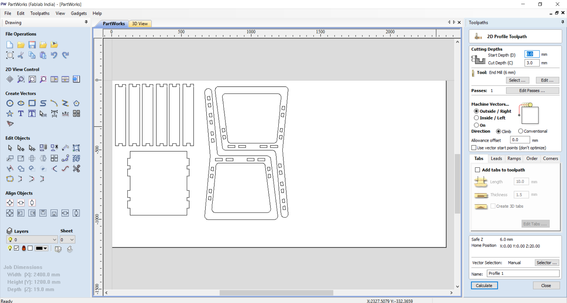
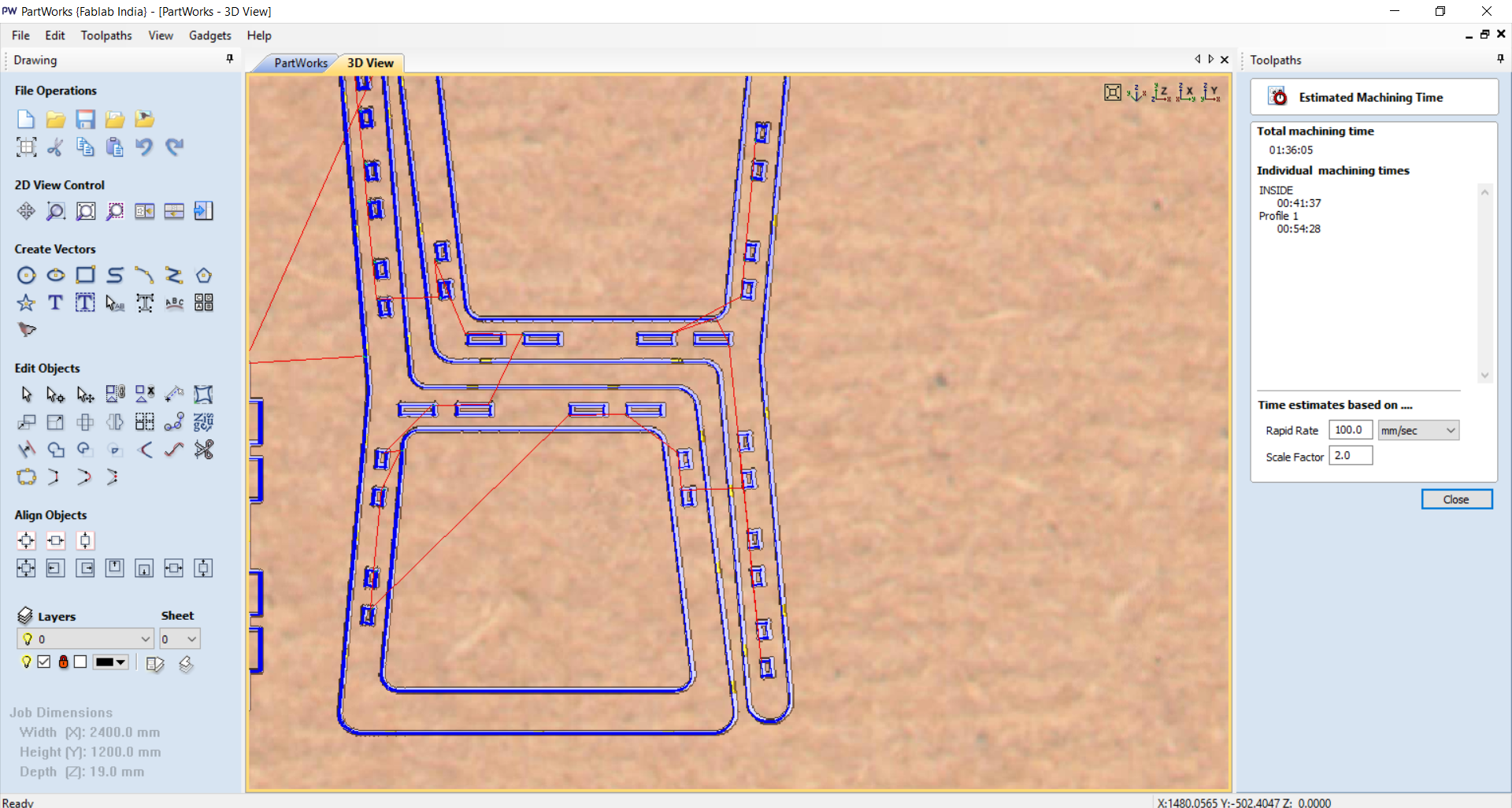
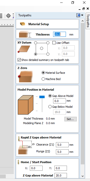
- Now i have to confirm cut depth: starting depth from 00.0 to 19.2 |mm|
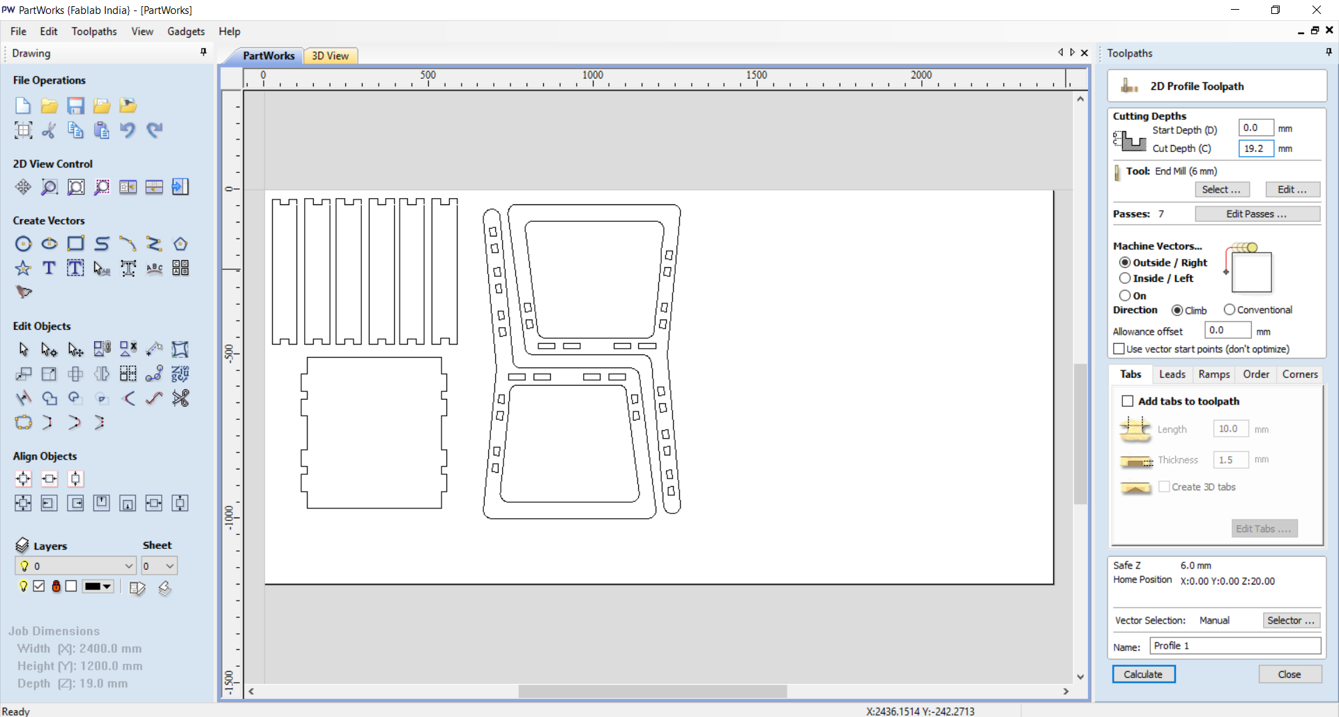
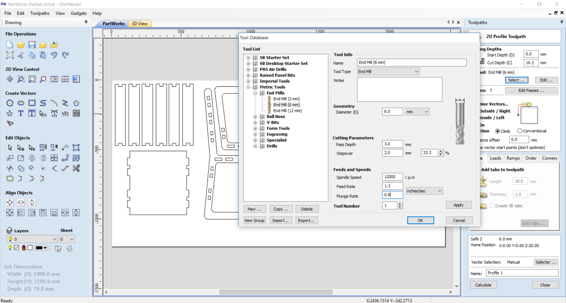
- Now, select tool for milling(Routing),Goto tool database select endmill drill bit (6mm).
- Spindle Speed : 12000rpm
- Feed Rate : 1.3
- Plunge Rate : 0.8
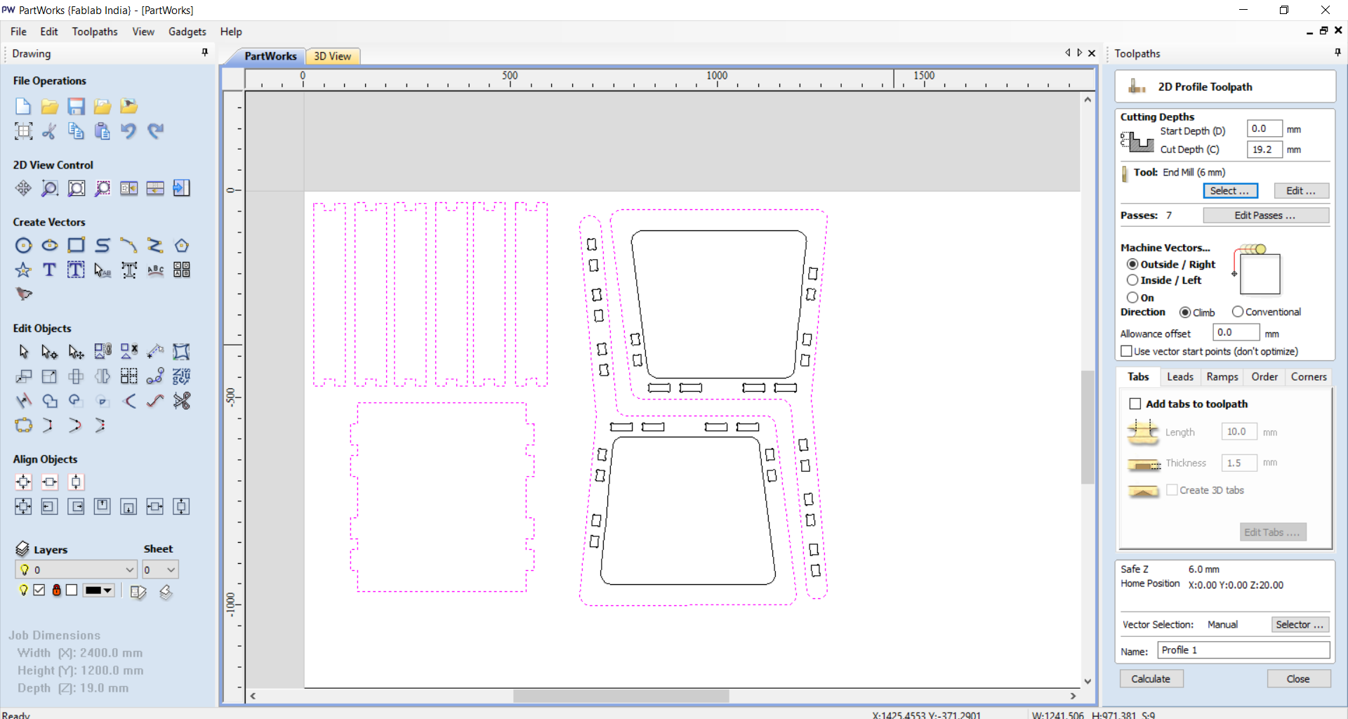
 - Select section to outcut....
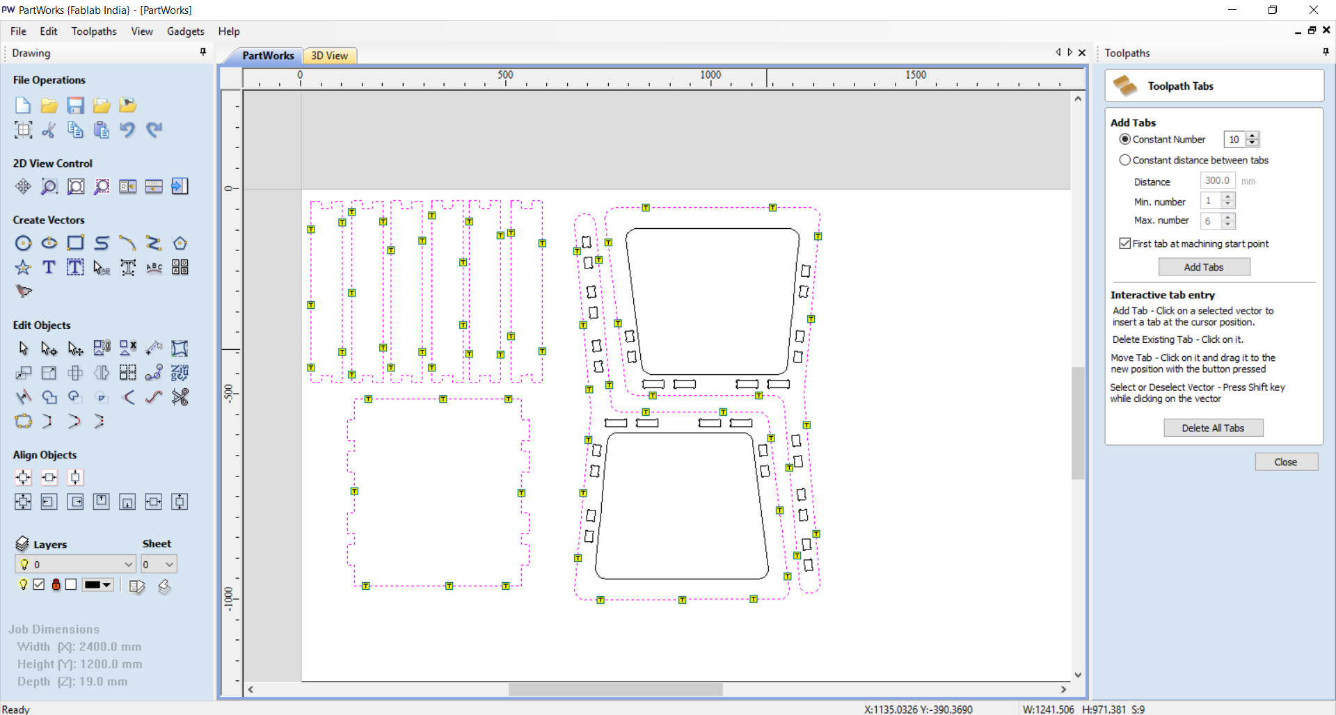
 - Now putting tab between that, Why tabs?
tabs help to cut that parts and that should come off while milling for precaution for that we put tabs.
- Now putting tab between that, Why tabs?
tabs help to cut that parts and that should come off while milling for precaution for that we put tabs.
 - Now select profile to make that toolpath, In 3D partworks there is a feature of minulation .
 - Now select innner part for in cut that should bee incut in my sheet.
 - As as we build tools for outer as same as we have to do for inner.
 - Build the toolpath individual for the my design.
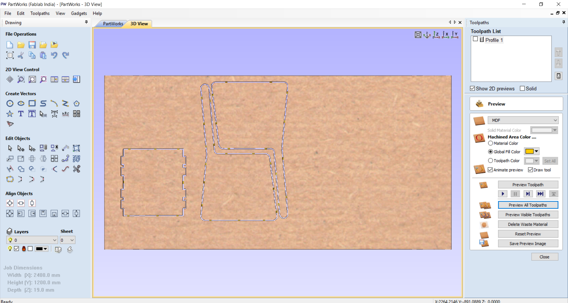
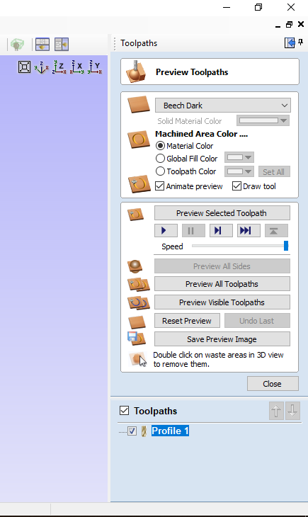
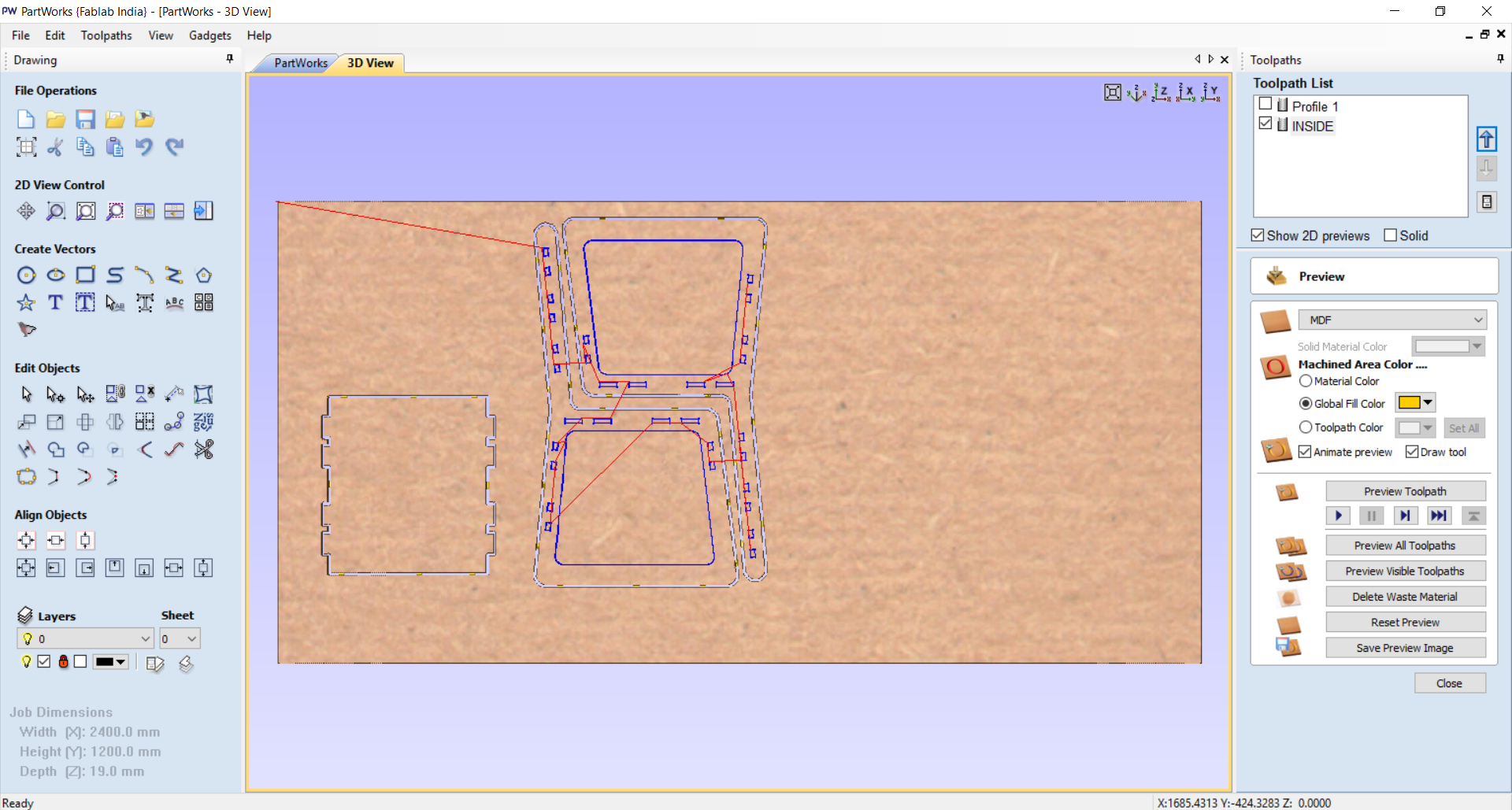 - After generating toolpath we will see there is an option to preview the machine working part.
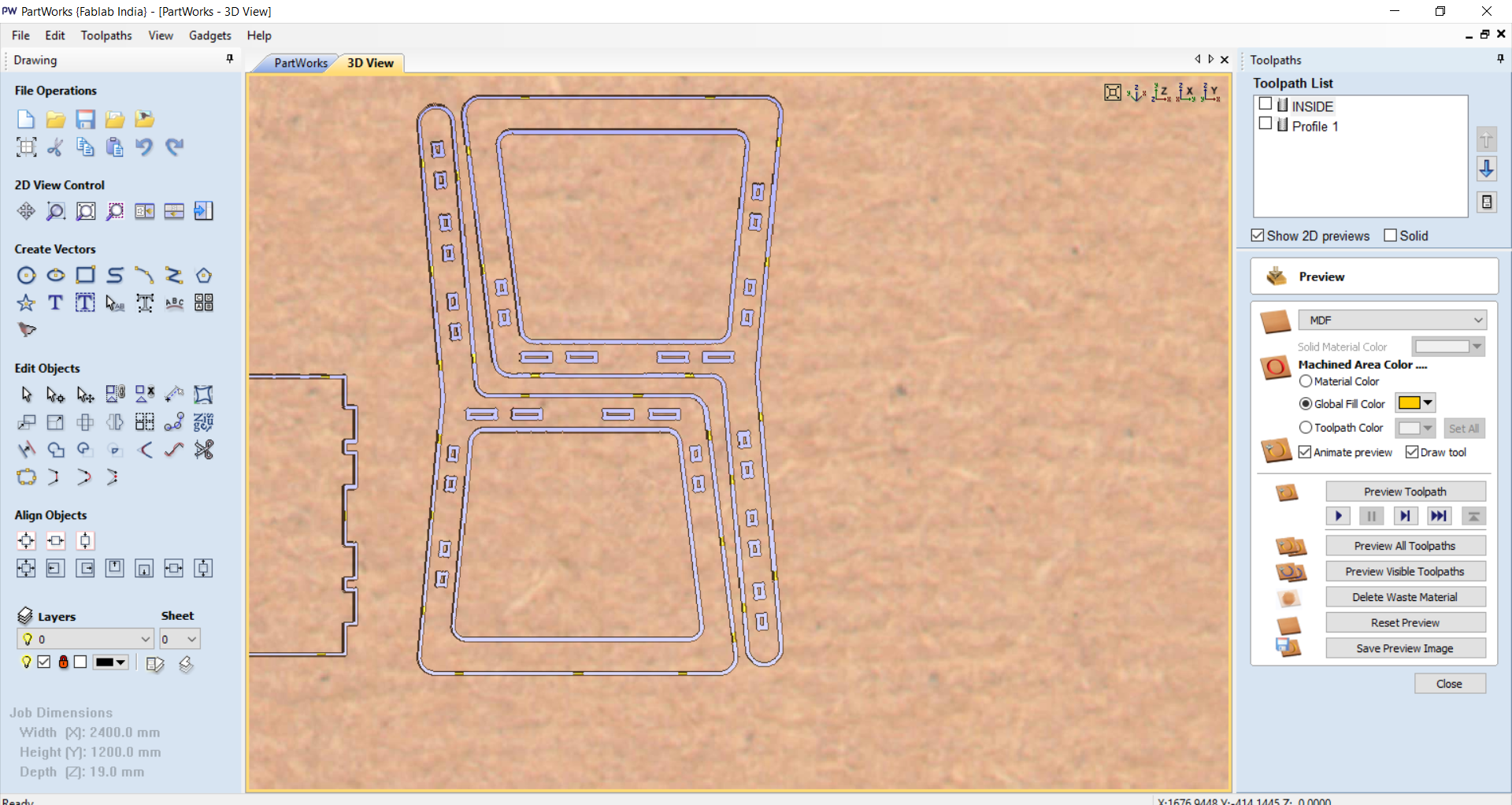 - As we conssidering the machine timing.
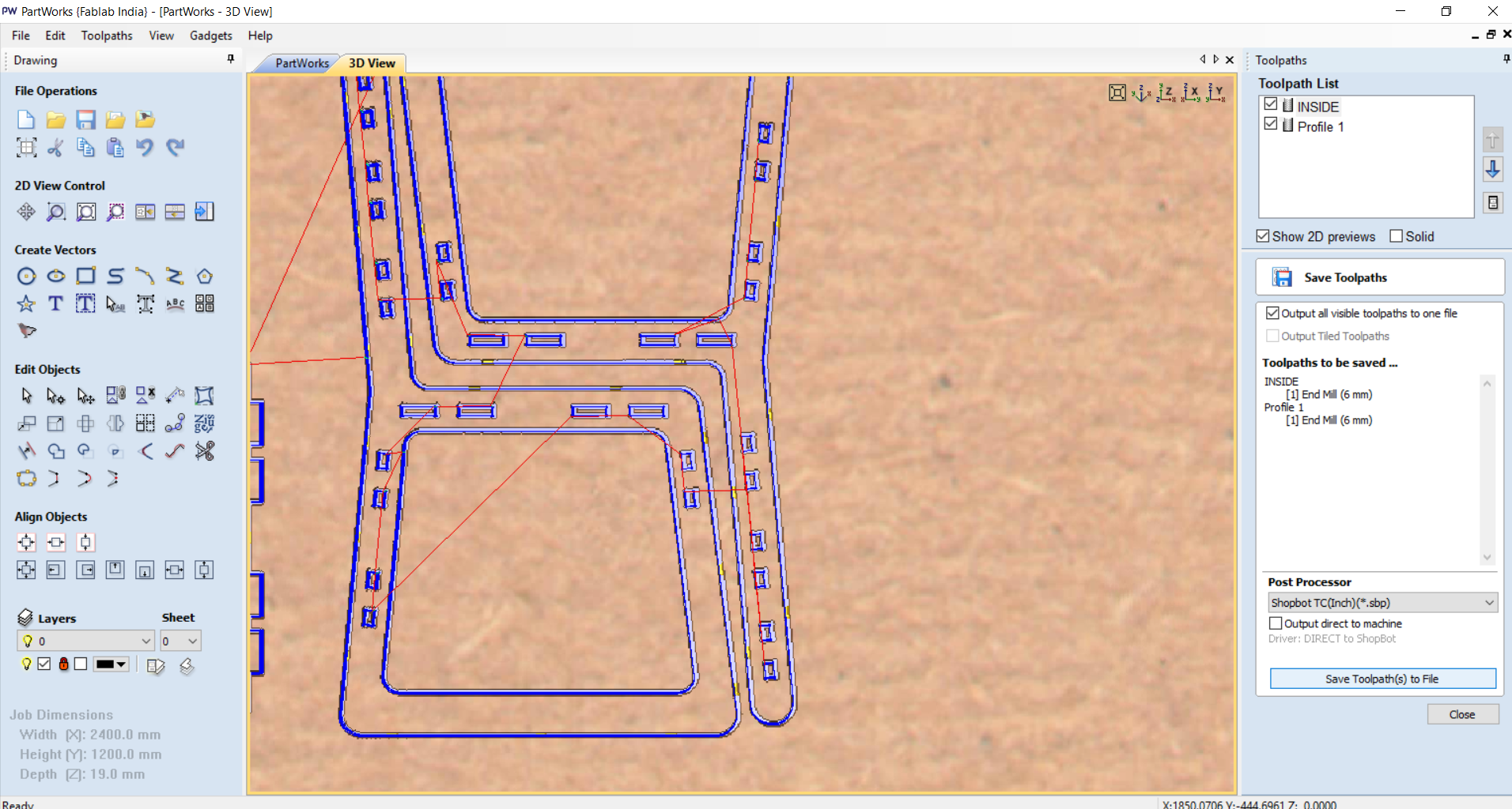
 - Select both toolpath and save the both file.
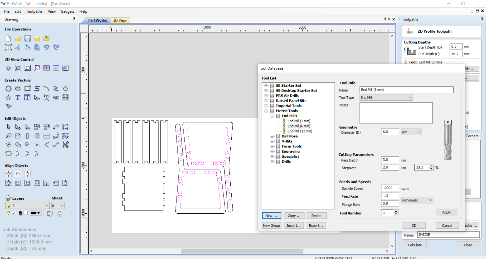
SELECT TOOL
-
I used 3 mm endmill milling bit for cutting.
-
Pass Depth : Pass depth determines in how many phashes you want to cut the material.
-
If i Put directly 12 mm here , it will go straigh 12 mm down. it is not advisable beacause tool will face very high forces than , so i decided to give 3 mm passes. each time tool will go 3 mm down after completing one cutting cycle and my material will be cut in 4 phashe(12/3).
-
Spindle speed : it determines RPM of the Spindle.
-
Feed rate : it determines Feeding Force applied on material.
-
Plunge Rate : Plunge rate is the speed at which the router bit is driven down into the material when starting a cut. if is too High it will break the tool or make crack on surface of material.
 - Save the file on shopbot in INCH format.
- After generating the Toolpath now its time for cutting operation. After opening the SHopbot it is good practice to level up the machine for a while and Run Spindle worm up command. it will Re-circulate the oil on Spindle assembly.
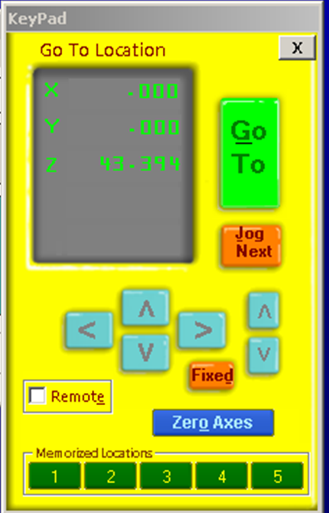
calibrating CNC machine’s axis, jump to x,y.
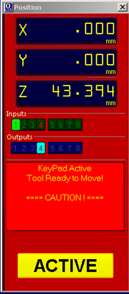
After confirming 0,0,0(x,y,z) lock the machine and click on active.
 Settle my sheet (19mm ply)
set Z axis zero and start machine

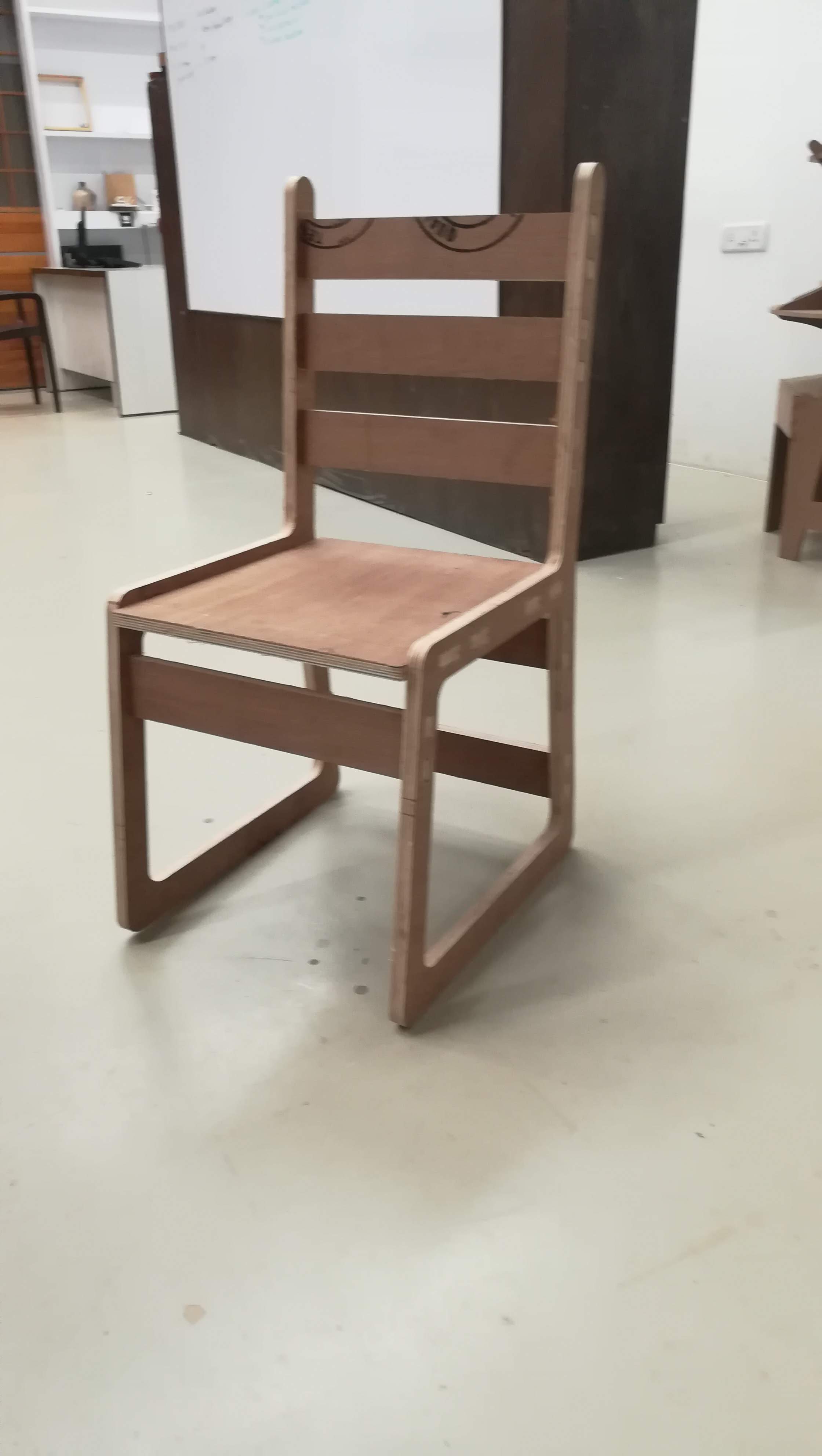
Hero Shot: