5. Electronics production
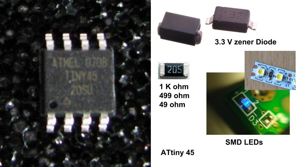
Make an in-circuit programmer by milling the PCB, program it, then optionally try other PCB processes ATtiny45
Visit Group website for more imformations. Click here.
Electronics production
What is Electronics production?
In process of electronics components, the action of making or manufacturing from components or raw materials, or the process of being so manufactured. This manufacture is known as Electronics production
What is PCB and it’s type?
Single-Sided PCBs
This single sided printed circuit board incorporates only one layer of base material or substrate. One end of the substrate is covered with a flimsy layer of metal, as a rule copper since it is a decent electrical transmitter. Generally, a protecting solder mask be situated on the pinnacle of the copper layer, and a last silkscreen coat might be connected to the best to stamp components of the board.
Double-Sided PCBs
This kind of PCBs is substantially more natural than single-sided sheets. The two sides of the board’s substrate incorporate metal conductive layers, and components append to the two sides also.
Openings in the PCB let circuits on a solitary side to join to circuits on the opposite side.
Multilayer PCBs
These PCBs further enlarges the density and complexity of PCB designs by adding extra layers beyond the top & bottom layers seen in a configuration of double sided.
With the accessibility of over many layers in multilayer printed circuit board configurations, multilayer PCBs let designers to make very thick and highly compound designs.
Rigid PCBs
Notwithstanding having diverse quantities of layers and sides, Printed circuit sheets can likewise come in evolving rigidities. Most clients more often than not consider rigid PCBs when they picture a circuit board.
Unbending printed circuit sheets utilize a strong, inflexible substrate material like fiberglass that remaining parts the board from turning. A motherboard inside the pinnacle of a PC is the best case of an unyielding PCB.
Flex PCBs
By and large, the substrate in an adaptable board is an adaptable plastic. This central material allows the board to fit into structures that firm sheets can’t and to turn or move amid use without destructive the circuits on the printed circuit board.
In spite of the fact that flex sheets will in general charge more to plan and make than unbending PCBs, they accompany various focal points. For example, they can reestablish overwhelming or cumbersome wiring in unrivaled rigging like satellites, where weight and space matter.
Rigid-Flex PCBs
Rigid flex boards merge technology from both flexible and rigid circuit boards.
An easy rigid-flex boards comprises of a rigid circuit board that joints to a flex circuit board. These boards can be more compound if design requests demand
What is meant by PCB fabrication?
Printed Circuit Board (PCB) fabrication is the assembly method for circuit boards used in electronic and computer devices. The layers of the board are put together along with the specific surface pattern so it can be used in electronics manufacturing.
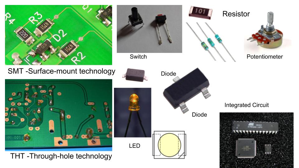
Electronic (PCB) Components:
An electronic component is any basic discrete device or physical entity in an electronic system used to affect electrons or their associated fields.
- SMT -Surface-mount technology
- THT -Through-hole technology
- Switch
- Resistor
- Potentiometer
- Capacitor
- Diode
- LED -Light-Emitting Diode
- Transistor
- IC -Integrated Circuit
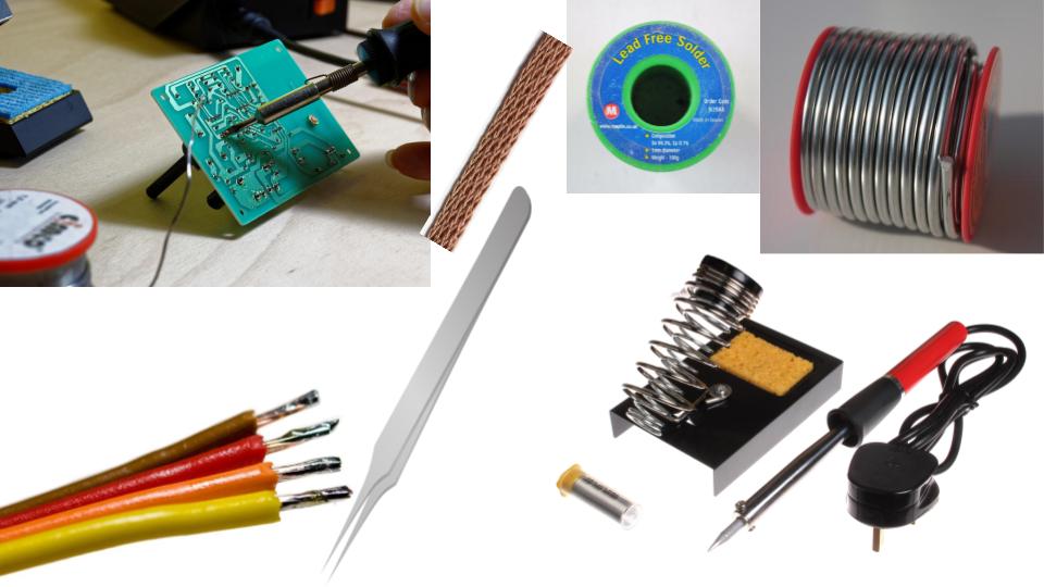
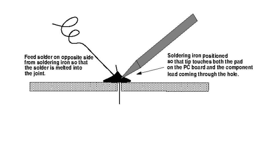
Soldering
What is Solder?
Solder, as a word, can be used in two different ways. Solder, the noun, refers to the alloy (a substance composed of two or more metals) that typically comes as a long, thin wire in spools or tubes. Solder, the verb, means to join together two pieces of metal in what is called a solder joint. __ Source: Wikipedia
Best Soldering Trick
What is the FabISP?
The FabISP is an in-framework developer for AVR microcontrollers, intended for generation inside a FabLab. It enables you to program the microcontrollers on different sheets you make.
The Electronics Production task is to process the board, stuff it with parts and program it. We will utilize these software engineers through the semester to program alternate sheets we make.
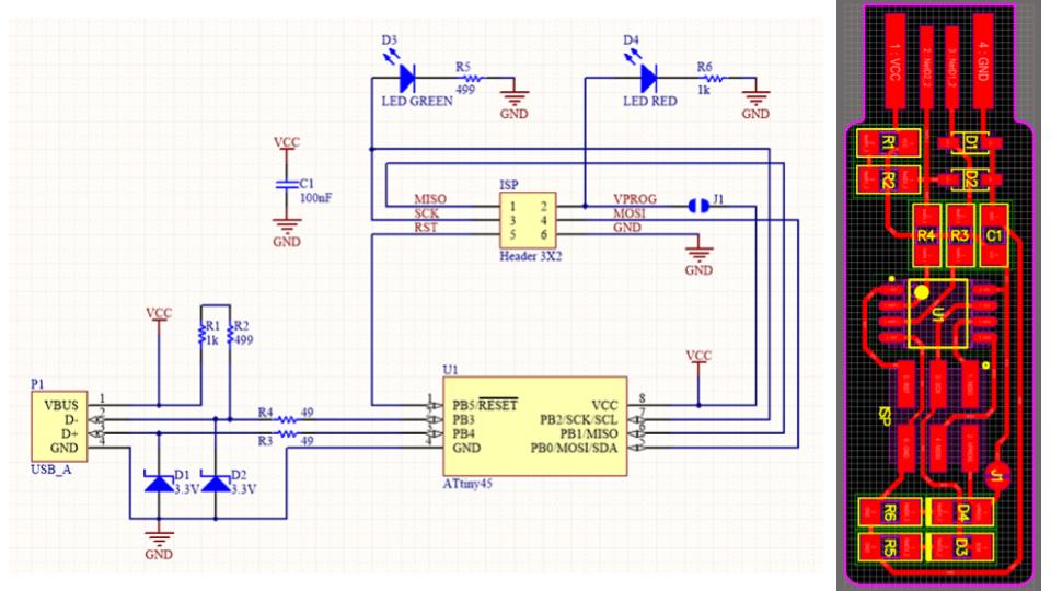
As I comprehend the Basic FabISP has experienced numerous progressions throughout the years by various individuals. The ISP in particular ATtiny 44 and ATtiny 45 are named after their IC. I have utilized ATtiny 45 that was produced by BRIAN
PCB Milling
Printed circuit board milling is the process of removing areas of copper from a sheet of printed circuit board material to recreate the pads, signal traces, and structures according to patterns from a digital circuit board plan known as a layout file.
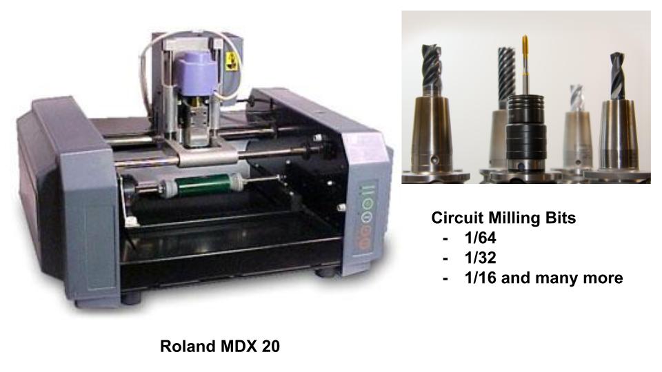
In our lab, we have a Roland: Modela RDX-20. As I am using Brian’s design for my ISP I downloaded the png from here:
-
MODELING FUNCTION
-
TOOl chuck : 6 mm
-
Spindle motor : 10W
-
Softwere resolution : 0.025mm/step
-
Mechanical resolution : 0.00625mm/step
-
RPM : 6000 rpm
-
Feed rate : 0.1 mm to 15mm/sec
-
Export file formats : DXF,VRML, STL, IGES, Grayscale, BMP
-
Acceptable tool : Endmill, Drill
Followed this step by step instruction to install gcc-avr
The following are the commands used.
-sudo apt-get update

-sudo apt-get upgrade all

-sudo apt-get install GCC-avr binutils-avr avr-libc

-sudo apt-get install gdb-avr

-sudo apt-get install avrdude
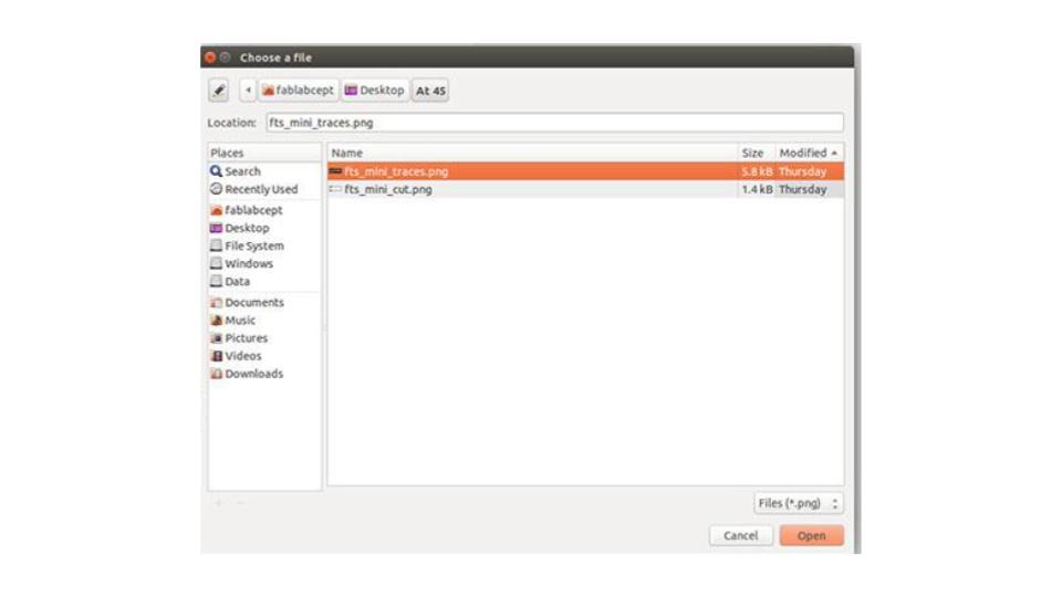
Creating Image/ circuit
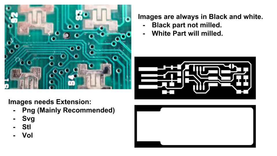
- Prepare an PNG image / Design Circuit in Software like eagle.
- Make image Black and White(Pattern :White part became milled(subtractive part))
- Make size in that software and export after confirmation.
- Send/Tranfer file to FAB-PC (We have to work on linux that why!)
Pre-prepartion for milling
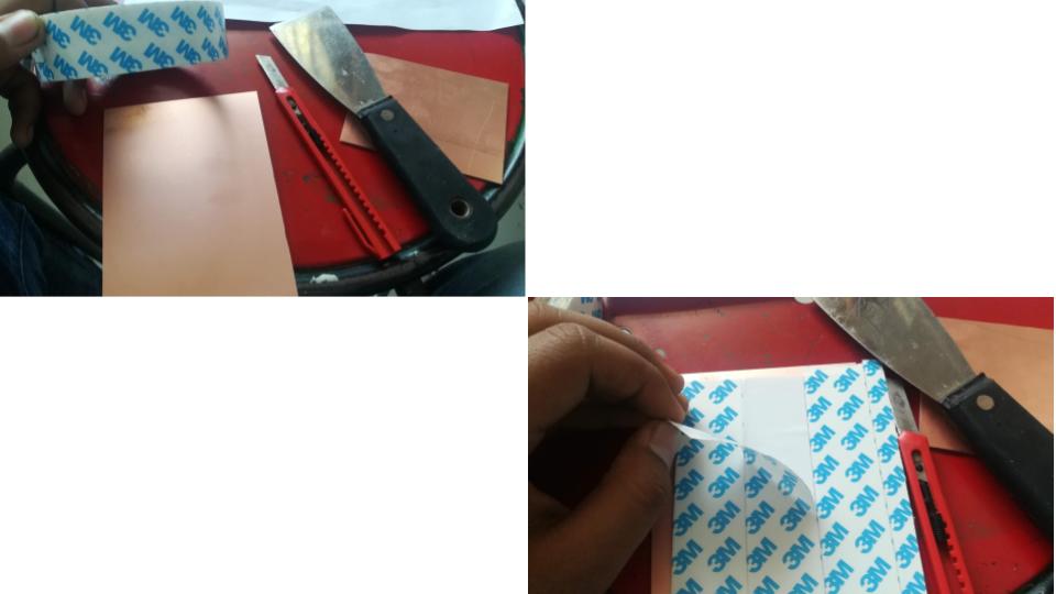
- Take copper coated board as you requied.
- Take a level surfaced board(Don’t Use bended board).
- Check Level of milling machine.
- Now stick double side tape on bottom of board.
- Set “Z” axis manual became zero.
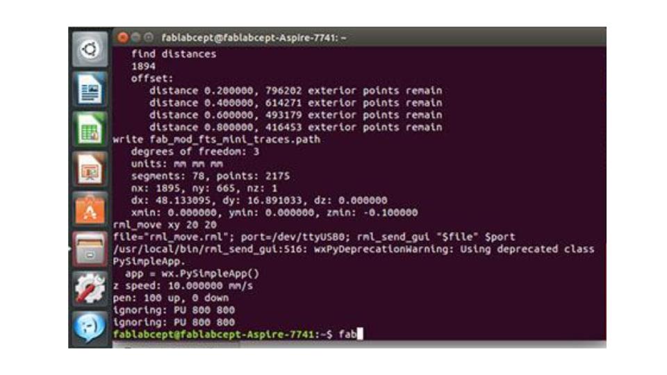
Machinery Operateing Interface
- Power On the system
- Open terminal
- Type command
- ~/Desktop
- cd fabmodules
- npm start
- MSG DISPLAY=listening for connections from 127.0.0.1 on 12345
- Open Browser
- http://localhost:12345 or http://127.0.0.1:12345
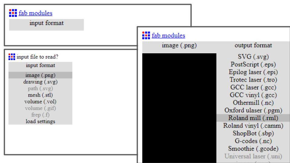
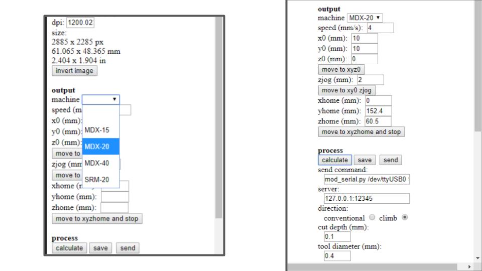

“fab modules”
- Input format >> .png.
- Output format >> .rml.
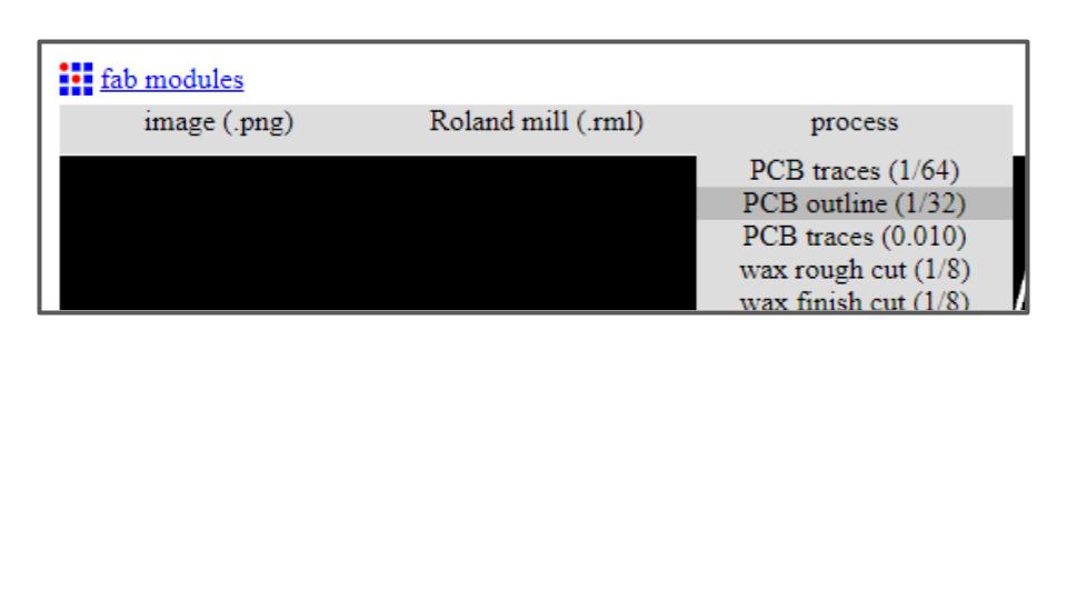
- Process >>
- 1/64 for trace
- 1/32 for outline
- Select Machine >> MDX-20
- Set Speed >> 2
- Set x,y axis(z axis setted manually)
- Set cutdepth >> 0.1
- 0.09 (is good)
- 0.13 (Little risky)
- 0.17 (Warning)
- Direction >> climb
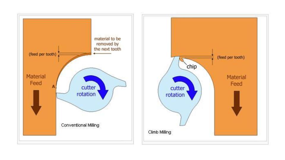
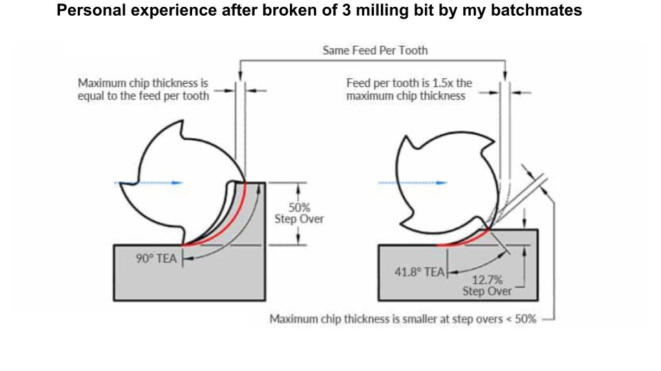
- Slow speed and less substraction help to long life of milling bit
- Offset >> 4
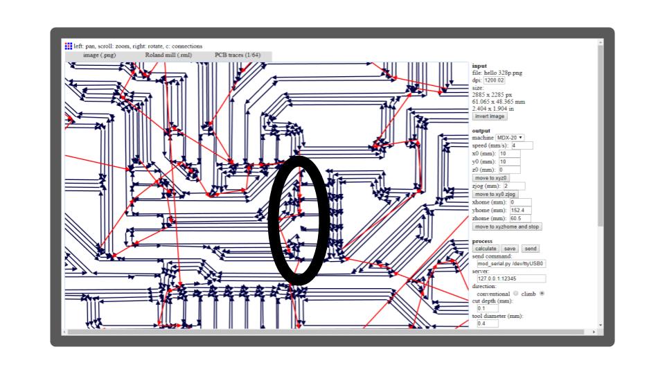
- Process ==>> Calculate
- wait for trace is fully displayed!
- ==>> send
Why??
- 1/64?
- 1/64 bit is utilized for follows as it is more slender and accomplishes processing for little parts
- 1/32?
- use a 1/32” flat end mill to mill holes, and outlines.
Cut depth
- Cut depth is how deep you want your tool to go in the Fiber-copper board. 0.1 is good for tracing operations and 0.6 is good for cutting operations
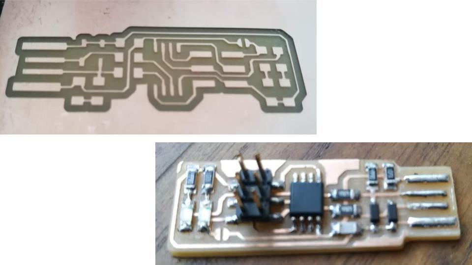
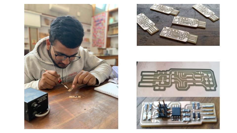
After Milled
- Remove milled PCB from bed.
- Rub with 1000 Grid Sand paper to make clean.
- After cleaning Soldering is easily done on that.
-
Collect all need component from FABLAB Component library.
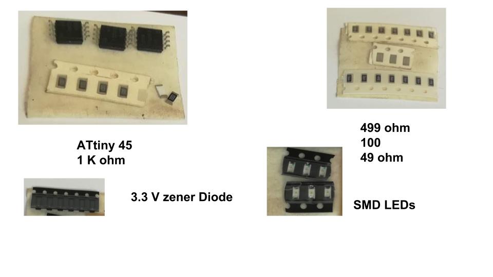
-
With use of Soldering station we have to solder PCB.
- Solder station which have solder iron, solder wire, Hot air gun, Voltage regulater.
- Using soldering paste we can easily align the component.
- Check ISP with Multimeter that in any case any component is sorted or not.
- If any sort then correct it!
- Now we are ready to program it.
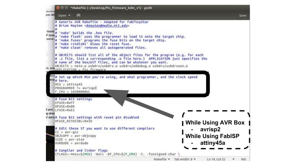
Programming ISP
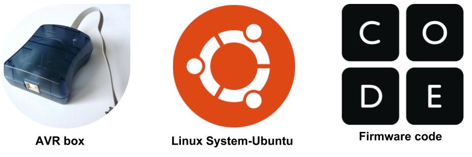
- I need to install AVR GCC.
- Follow the link. Firmware
-
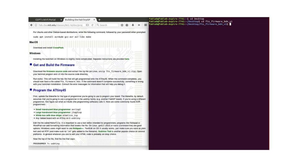
Downloading Firmware and then unzip to a Folder.
-
Connect Your ISP to AVR loader and Laptop
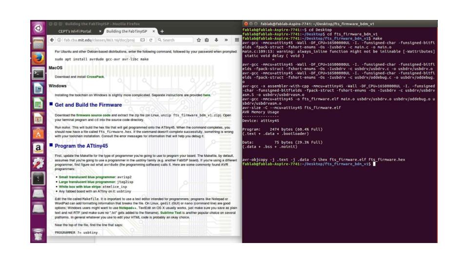
- Go to folder in Terminal.
- now you need to enter commands in terminal and check the folder.
- make
- make –always-make
- (This will aleady created) (Use this command to program it)
- make fuse
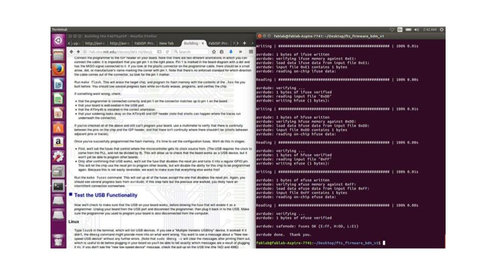
- lsusb(To check it is program well!)
Testing the working of Fab-ISP
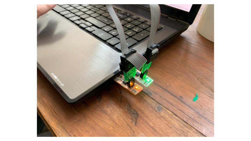
Connect ISP to the computer via Micro USB cable and one end to the AVR.
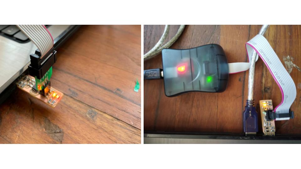
It is showing red light which denotes that ISP is not working due to the following problems:
- solder bridges while soldering
- problematic soldering of components
- overheating of elements while soldering
- failure of components due to overheating during soldering
Problems occurred:
- overheating of elements while soldering
- solder bridges while soldering
- problematic soldering of components
- failure of components due to overheating during soldering x
Links
File
Conclusion
This week is about electronic creation. The essential goal of this current week is to comprehend what a circuit is, the distinctive sorts and segments of a circuit board, processing a PCB and patching. The address talked about PCB manufacture process, sorts of PCB and segments relying upon the kind of PCB. At that point top to bottom, we were educated about welding and its materials.