17. Machine Design
group assignment
- actuate and automate your machine
- document the group project and your individual contribution
You can read the full machine documentation in our group webpage
Individual contribution
For this week’s assignment I’ve contributed setting up the motors for the project. Also documenting our work and publishing it on our webpage.
Every topic below was written / developed by myself.
Updates and new course of action
The previous design proved to be too close to the body to properly make a scan. Instead of just adjusting the size, we decided to go for two separate modules, one turn table and on big axis for the scanner.
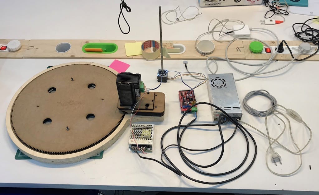
While the others went working on the new mechanic design, I started gathering the motors and drivers we had to automate the machine.
Controlling steppers is something I’ve seen a lot, and actually assembled a couple of printers and CNCs, but never build one machine from scratch. So I still had a gap on exactly how everything works standalone.
Turn table motor
Model: IHSS60-36-30-31
Input voltage: 20-50VDC (36V typical value)
Output shaft diameter: 8mm
Torque: 3Nm
Maximum pulse frequency: 200K
Default communication rate: 57.6Kbps
Continuous current: 4A
Datasheet: https://www.cnc-technics.de/stepper_motoren_integrated.pdf
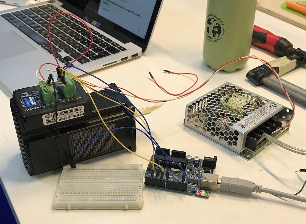
Since this motor already has a driver, I’ve decided to wire it directly into an Arduino to test. It took a while to understand what was needed in order for it to work. I only managed after finding this wiring diagram and with the help of the instructor to get the AccelStepper library up and running.

#include <AccelStepper.h>

#define stepPin 2
#define dirPin 4
#define enablePin 6
#define pedPin 8

AccelStepper stepper(1,stepPin,dirPin); // Defaults to AccelStepper::FULL4WIRE (4 pins) on 2, 3, 4, 5

void setup()
{

   pinMode(enablePin, OUTPUT);
   pinMode(pedPin, INPUT);

   digitalWrite(enablePin, HIGH);
   delayMicroseconds(10);

   stepper.setMaxSpeed(1000);
   stepper.setSpeed(200);

}

void loop()
{
   stepper.runSpeed();
}
Once we managed to get everything in place, it started working.
Since the power supply is 24v, one little addition in this setup was wiring a voltage regulator to power the Arduino board with 5v through the Vin port, and the motor would spin without the need of a computer.
Our timing was really good with this one. A couple of minutes after wiring the motor, the other students arrived with the base plate ready, so we could test the whole setup.

Scanner motor
In order to set up another axis, I’ve decided to go for an easier way to control both in the future. After searching the lab I found a RAMPs 1.4 with an Arduino 2560.
This together with a 3D printer firmware like Marlin would be great to control the machine with any Gcode sender like Pronterface.
Searching for RAMPs documentation, most I could find was focused on full 3D printers, getting a bit overwhelming from start.
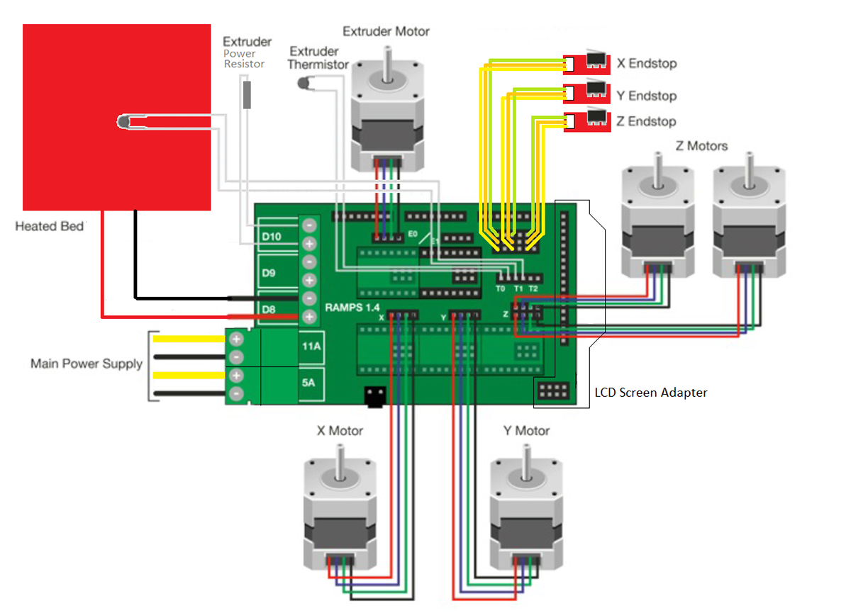
But then I found this really helpful video showing how to do it only for one motor:
After following the instructions to wire the motor with the driver, I’ve uploaded the firmware to the Arduino and everything seemed ok. But whenever sending a command, the motor would move just a little bit and freeze. Needing a complete reset in order to do the same thing again.
It was only then I realized one of the capacitors of the board was broken.
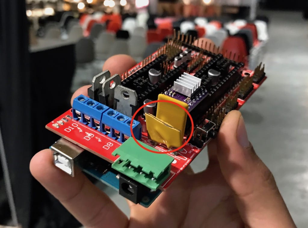
After getting another board. It started working normally.
Controlling both motors
Since the motors work in different voltages, I had to use two power supplies. One 12 and the other 24v.
After wiring everything and connecting the Arduino to the pc, I was able to control them individually.