11. Input Devices
assignments
individual assignment:
- measure something: add a sensor to a microcontroller board that you have designed and read it
group assignment:
- probe an input device’s analog levels and digital signals
Research
After the class, I decided to use a IMU as an input, since it gives me loads of possibilities to read the values and obtain different informations.
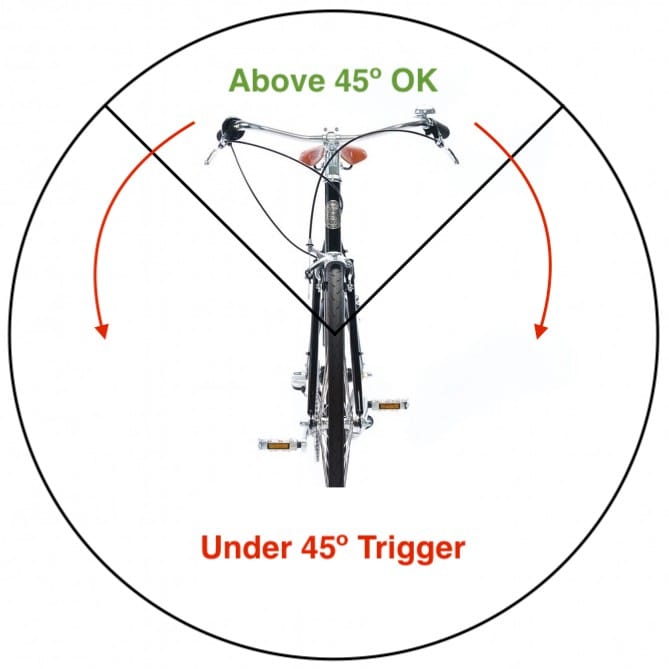
The most interesting one for me is safety. I can trigger an S.O.S if the cyclist crashes.
A simple method would be to check the orientation of the device. If is tilted less than 45º for more than X seconds. It means the bike is on the ground and something happened.
I’ve looked into Esteban Gimenez’s work and I’ll try to reuse this board with the other assignments as well (Networking and Interfaces). So, in my design I’ll try to leave as many pins as possible to program later.
PCB Design
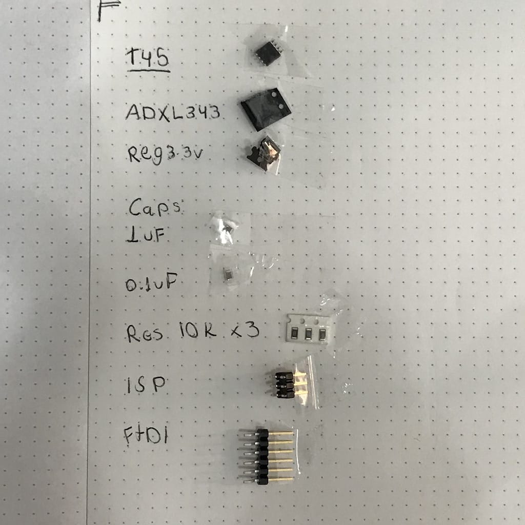
Choosing the components
Before starting the design, I wanted to make sure which components we had and what were the requirements for all of them.
IMU:
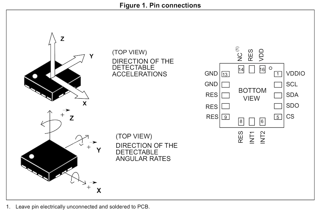
Recommended 0.1uF CAP on VDD and VDDIO
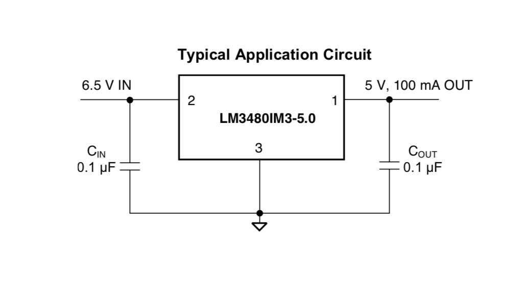
3.3v Regulator:
4/1 - Update
I could not work with this the last couple of days, so instead of doing something new, I’ll reproduce Neil’s example, doing everything again since the schematic. I believe it will be a good exercise as well. Specially because soldering such a small component as the sensor is a new process and challenge.
My final project will include a similar sensor, so I’ll have a chance to design a board for it in a couple of weeks, but with the acquired knowledge of how to do it and how it works.
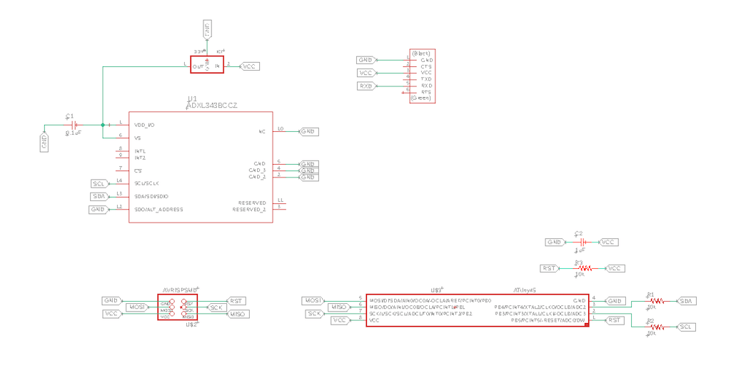
Schematic
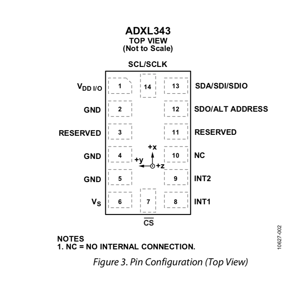
ADXL343 Footprint
As soon as I started in Kicad, I realized the fab library doesn’t have the ADXL343 footprint. And, to my surprise, neither do the Eagle one. Fortunately, the datasheet has the drawing with all the measurements, so I can use it in the worst case where I can’t find a ready one.
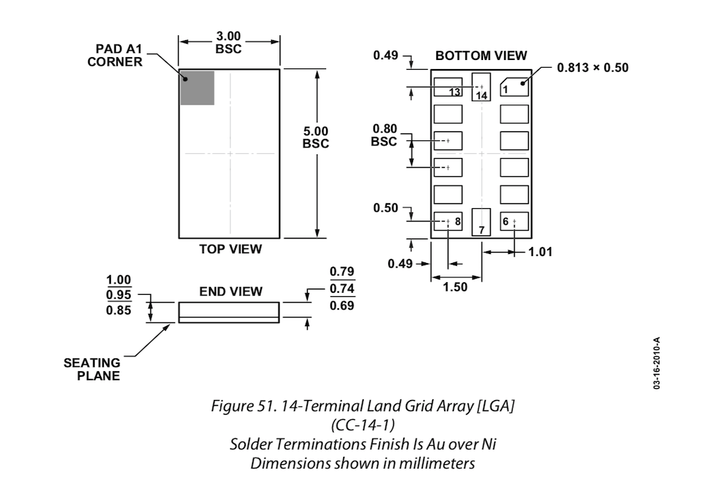
It seems that digikey has the appropriate items:
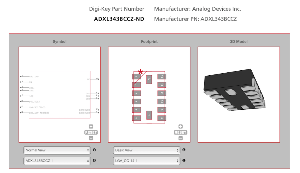
Download ADXL343BCCZ-ND footprint for Eagle and KiCAD
Drawing
I’m really impressed by how much i’ve forgotten! Practice is key. It took me a while to get familiar again with everything. And I’m pretty sure this is not the best schematic drawing, but I believe it works for now.
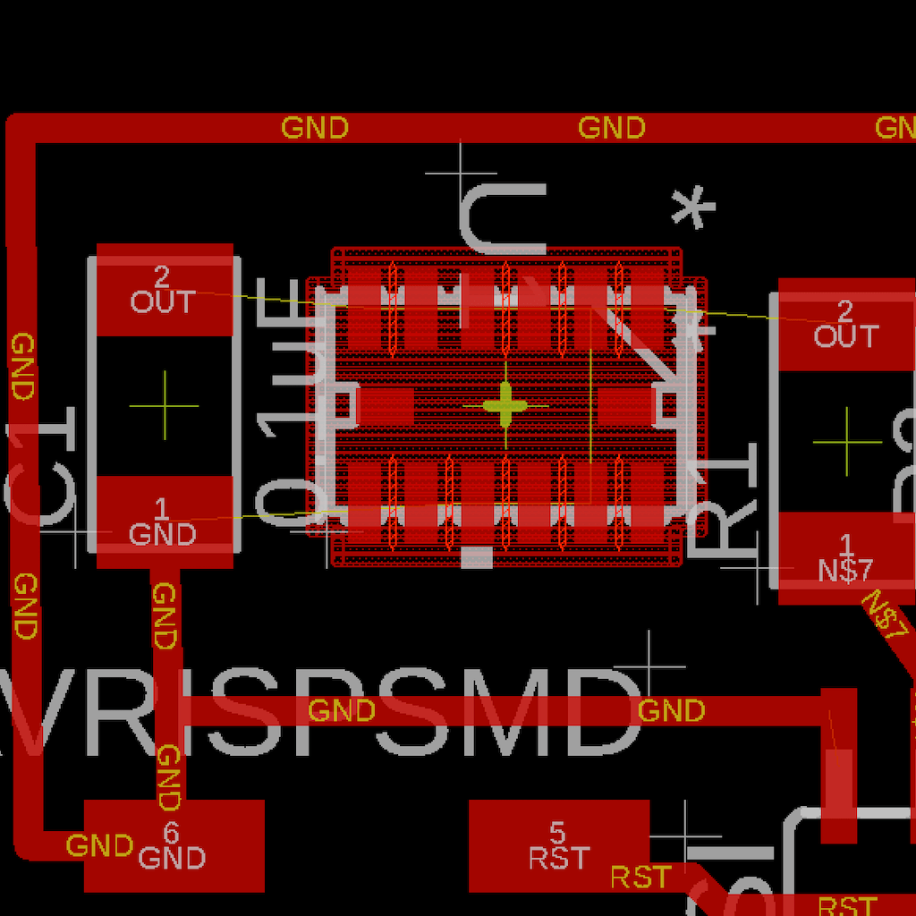
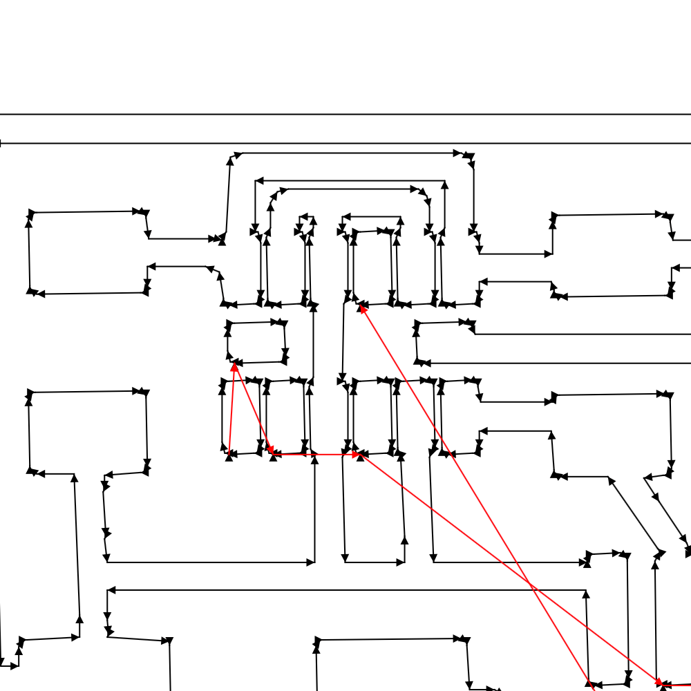
Routing
Started as usual, with all the components cluttered in one side, then went to arrange them as Neil’s board.
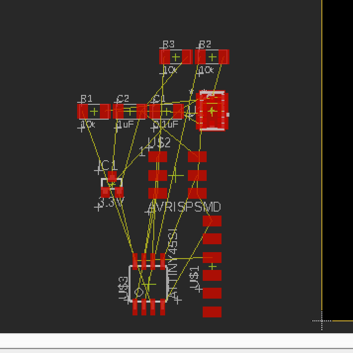
But, using the regular design rules, I’m not able to route such small component as the sensor. So I’ll have to use a smaller endmill and different rules.
Since we have a .010” diameter tool, I’ll change all the tolerances to that value and see what happens.
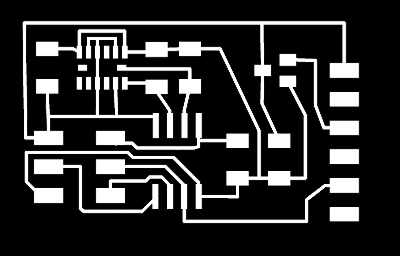
Final v1 DRC
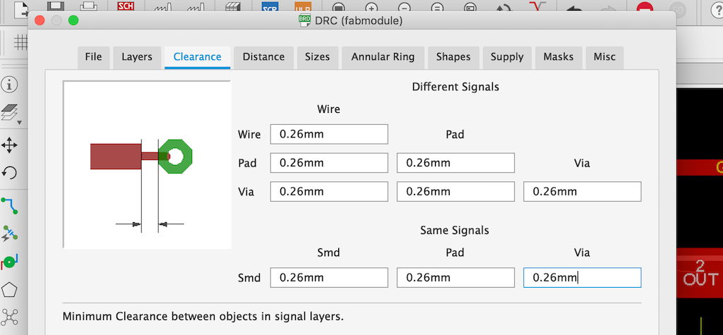
Final v1 Routed
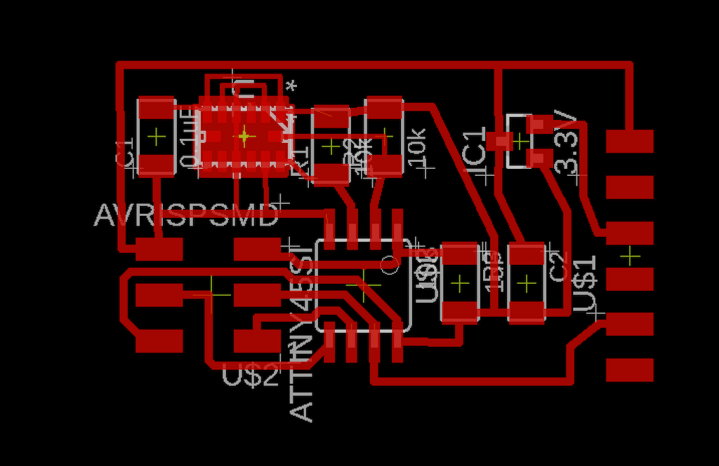
After checking the file with mods, I had to change the line widths to 10mils as well.
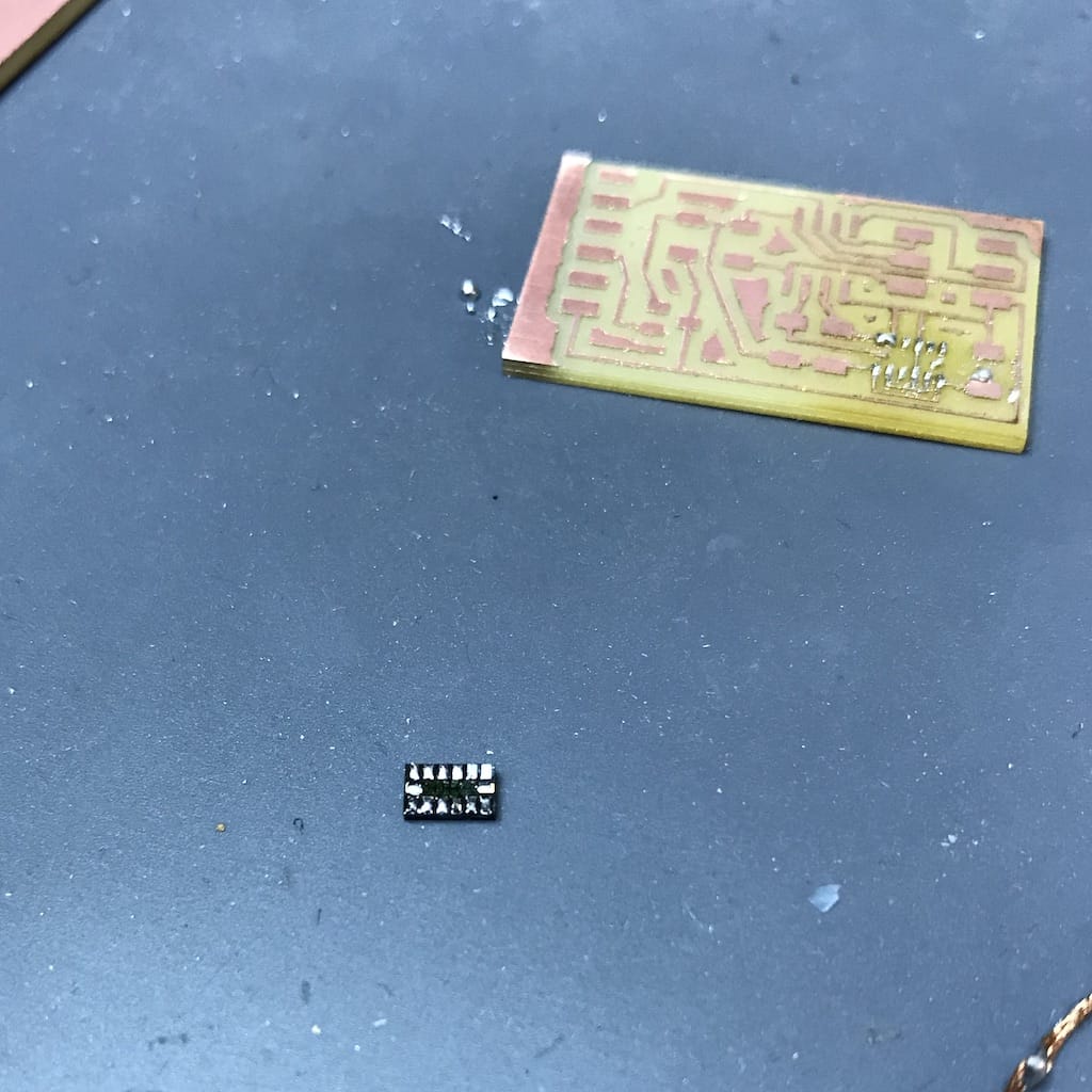
Now, I got to a point where a 1/64 cut everything but the sensor pads.
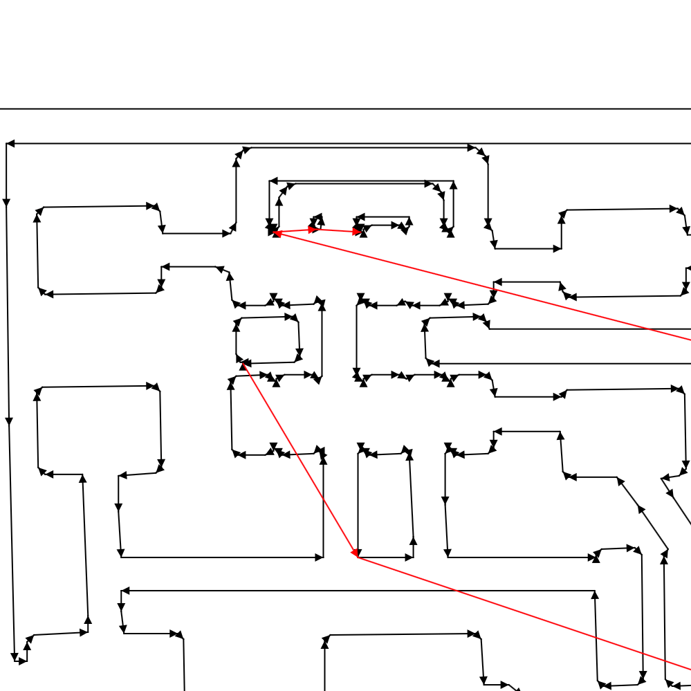
Milling PCB
This will be a three steps process:
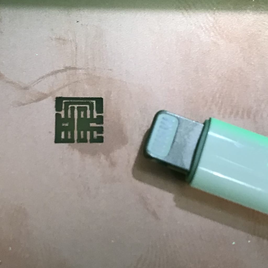
1 - 0.0100” mill for the pads with 0.5 speed

That is crazy! By far the smallest thing I’ve done!
2 - 0.0156” mill for the traces
3 - 0.0312” mill for the cut

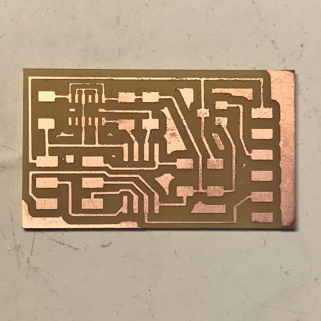
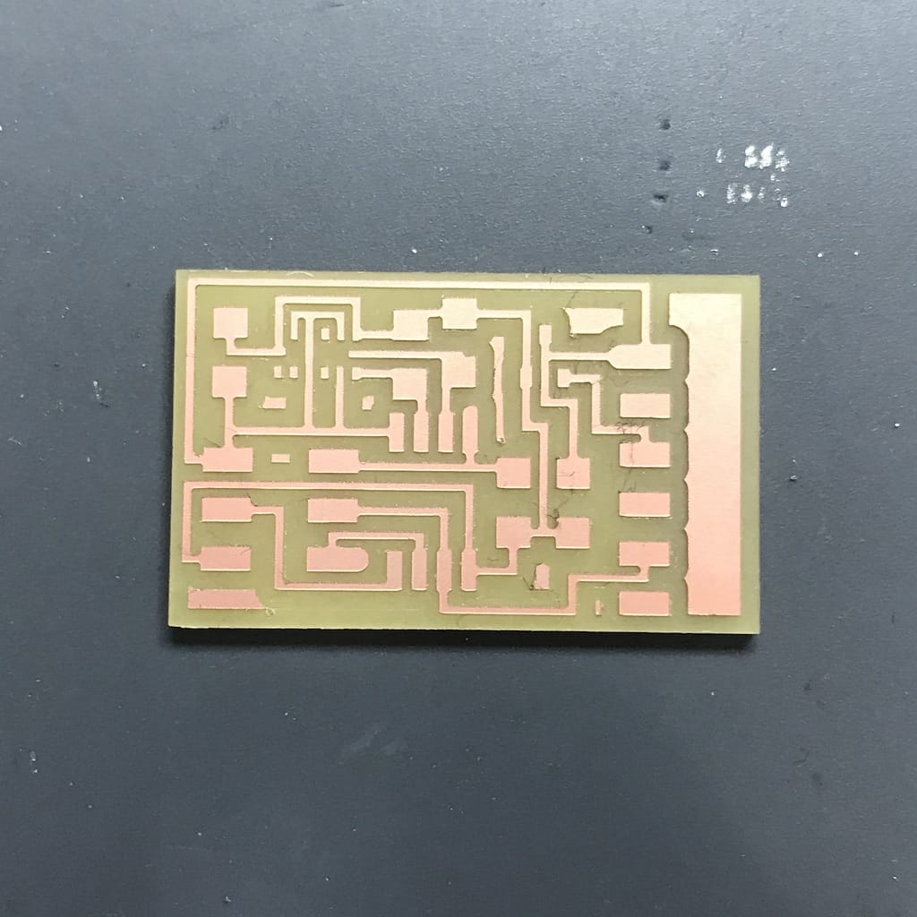
And that’s the result
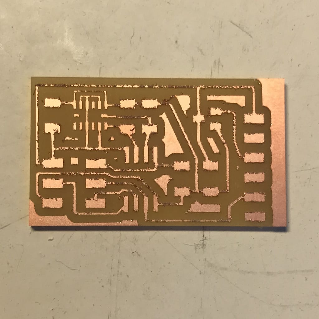
Since there was a little bit of copper left, I used a thin sandpaper to finish it.
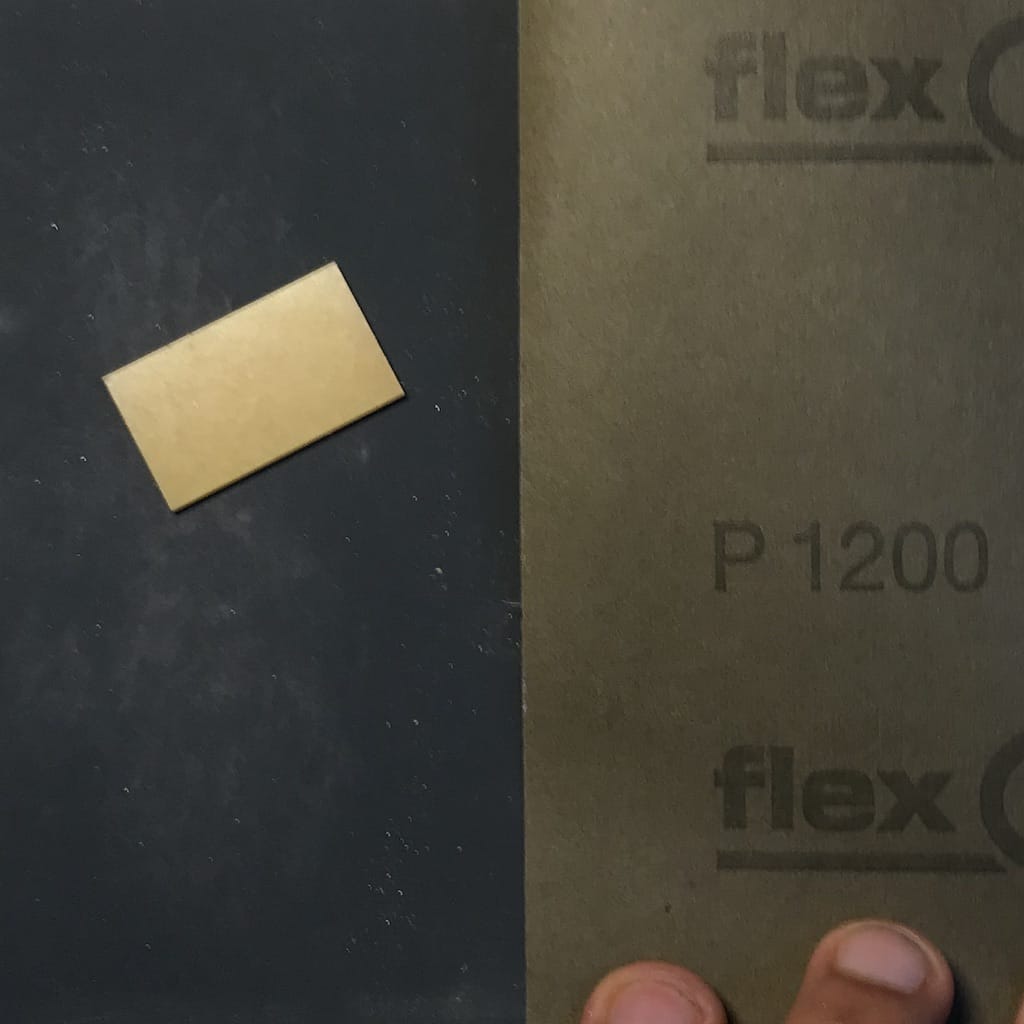
But, since I was afraid because of the thin trails, I just used a bit, but it improved the overall look a lot.
Components
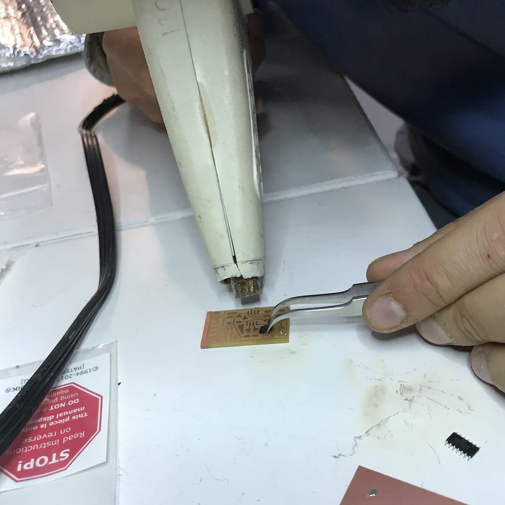
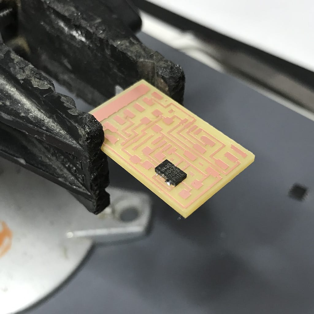
Soldering Accelerometer
Since I have such a small component and the components are below it, the traditional soldering with the iron would be almost impossible.
I asked the instructors and we have a soldering paste that can be used with a heat gun or an oven.
Since I’m not doing the whole board, just the sensor, I decided to use the heat gun. Later I’ll try doing everything with the oven.
I still feel I need to improve my traditional soldering. So this will be another good exercise.
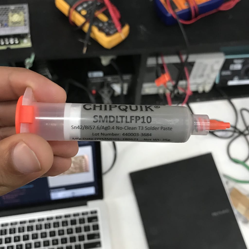
Even the tip of the syringe was too big for the sensor pads, so it took me a while to be able to get it into the correct tapes. Had to use the copper braid a couple of times.
Then, after a couple of tries, I started getting the hand for it. But even after it, I had to do it 2 times more. The first, I placed the component in the wrong orientation, the second, I had a short.
After having it in place and with no apparent shorts (checked continuity with the multimeter). I continued soldering the other components.
Programing
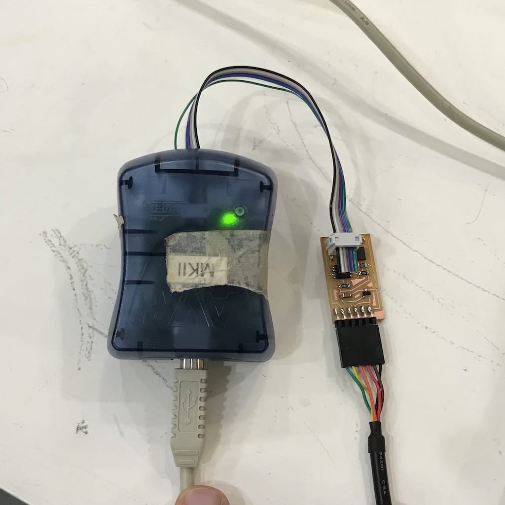
Even though the board has a regulator, I decided to use a 3.3v FTDI cable to power it. After getting it, had to use a different programmer as well. Since mine has the jumper that powers the board at 5v.
LED turned green, good sign.
Downloaded Neil’s code.
make -f hello.ADXL343.make program-avrisp2
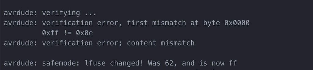
I bumped the board during the upload and got an error
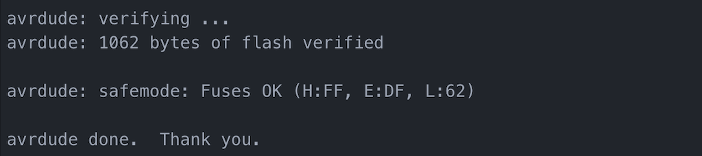
Then tried again and it worked
Tried python hello.ADXL343.py
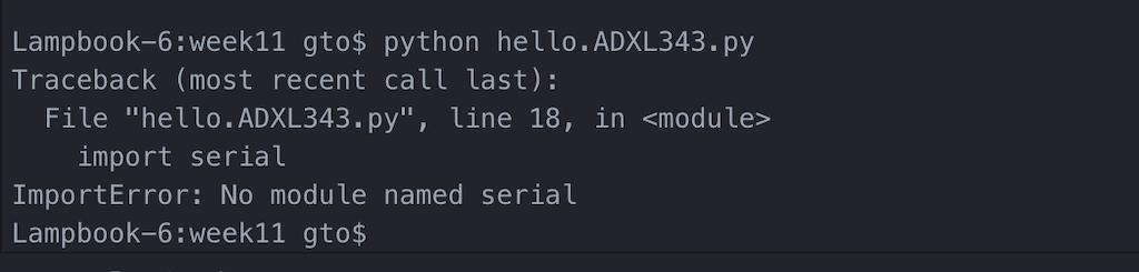
Seems like I’m missing the serial python library. Installed using:
pip install pyserial
After installing, I was able to run the script using
python hello.ADXL343.py /dev/cu.usbserial-FTFO8B3X
Debugging
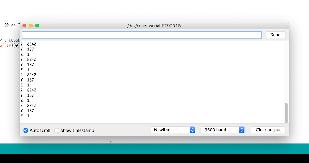
Since nothing was moving, I decided to check what I was getting in the serial with screen
screen /dev/tty.usbserial-FTFO8B3X 9600
I’m getting something but it doesn’t seem right.
After checking continuity and voltage across the board. I’ve gotten mixed results, but it seems to be fine overall, since I’m able to program it.
So my next step will be to isolate the sensor and just send a known char through serial to make sure it is working.
I was able to program the ATtiny45 and read strings via serial using Esteban Gimenez’s code, but the values from the sensor were not changing.
I’m going for another run at soldering the sensor to see if it works. It looks like everyone tried 3 times to make it work, so it may be a prophecy.
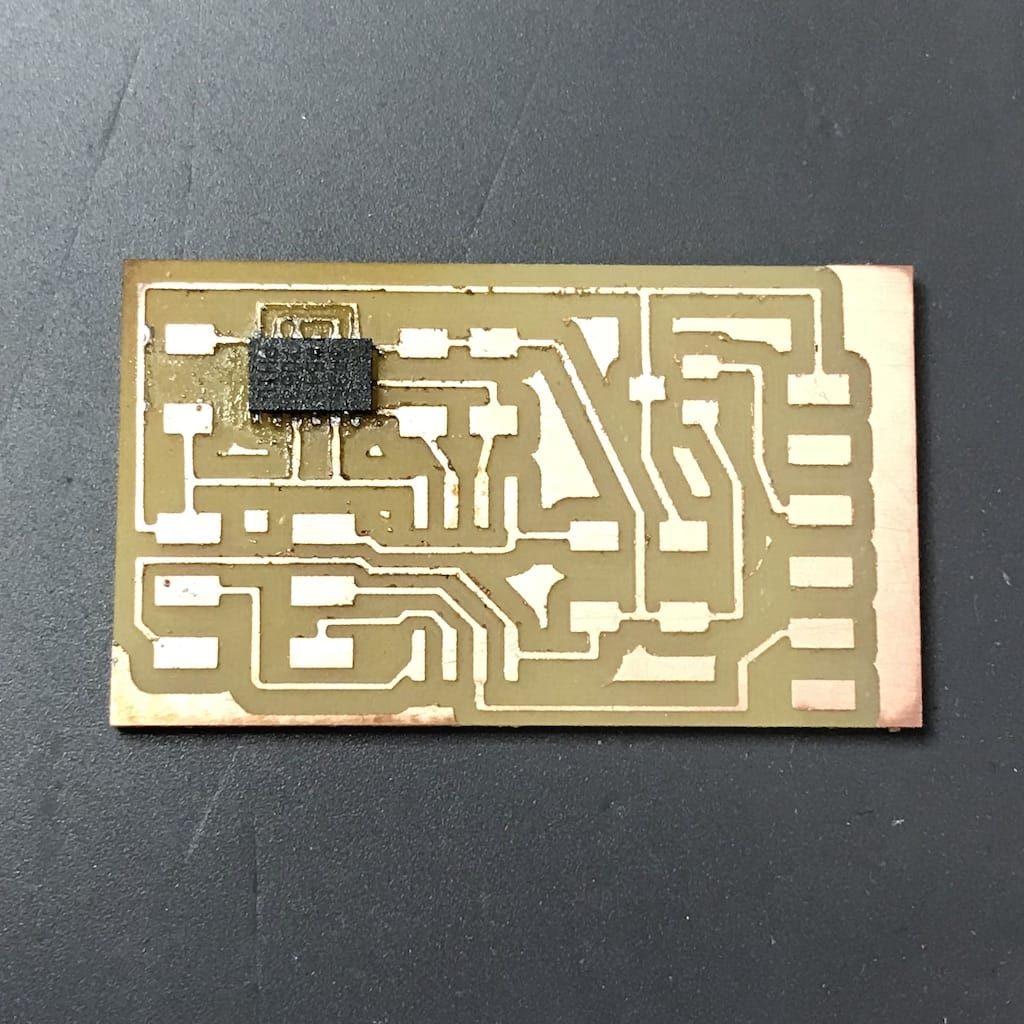
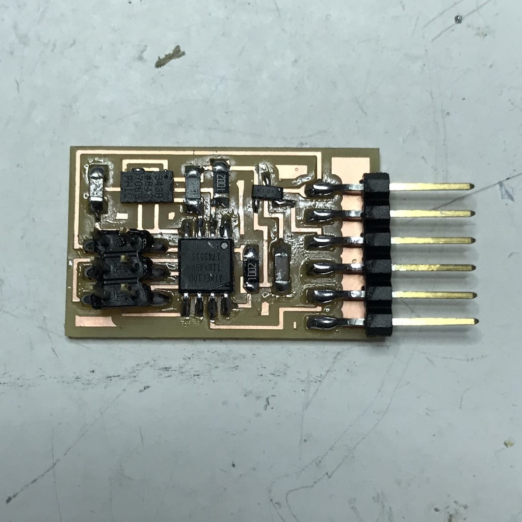
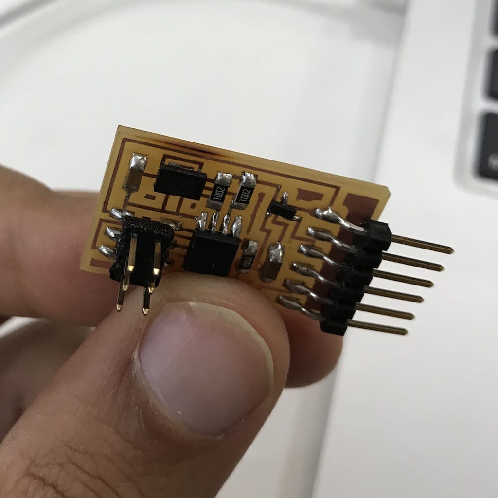
Doing it again
I’ve realized my board had a design problem. I was missing one connection. With this on top of the other mistakes, I decided to just make a new board. With larger traces, properly milled and with the right connections. To save time, I used the ready example and will update my design later.
I was impressed by how fast everything went, as from milling to soldering everything took way less than an hour. So I guess I’m starting to get a hand for it.
After placing the sensor I could see solder coming out of each ping, and after checking continuity with the multimeter there were no shorts. So that was a win.
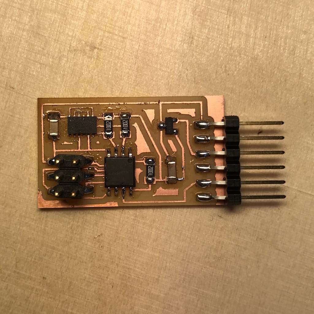
After soldering everything the board was ready for the test.
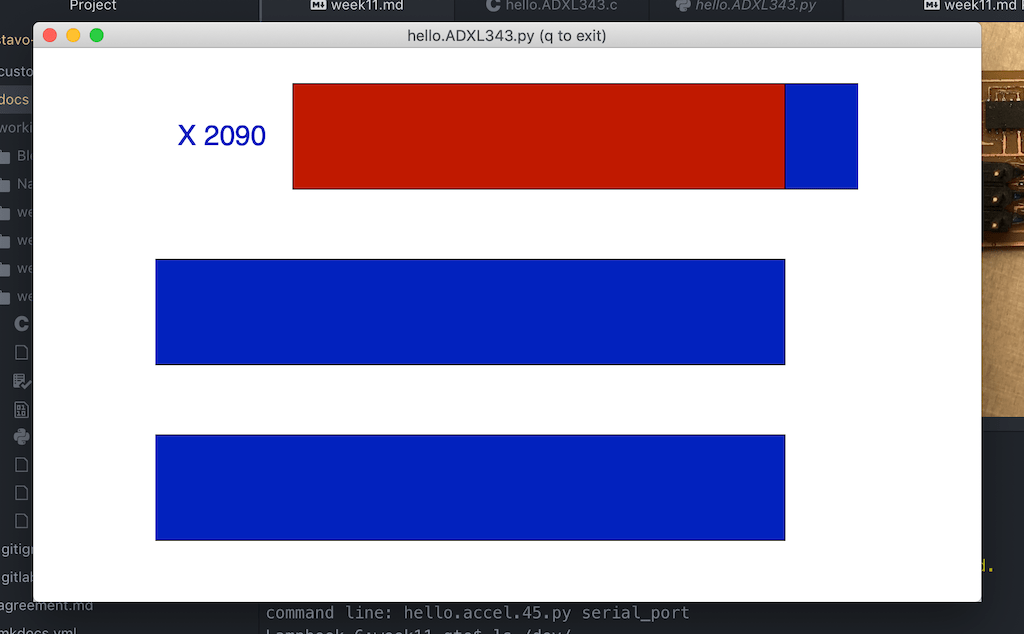
So I just repeated the process. Complied the C code and opened the python script.
And voilà!
My end goal is to create a breakout board with the sensor to use with my final project. But, in the process of removing the sensor one more time from the board, I burned it :(
Unfortunately the Lab did not have a heat gun with temperature control or a small tip for SMD rework. But the general rule of thumb is to try warming all the pads at once without heating too much the rest of the board.
Set the temp and air-flow to the appropriate settings (slightly higher than the melting point of the solder, and not too much air to blow your parts away). We recommend setting the air flow and temperature knobs to the middle and then test reflow on a small component.
The typical lead-free solder has a melting point around 217 degrees C. But it is common to use higher temperatures to speed up the process. But as it happened with me, if you see any color change on the board it’s a bad sign. I was not able to recover this board and I don’t think is even worth trying to scavenge the components. Since there is a high change of them being damaged.
So, for now I’ll use a commercial breakout board to test code. And when developing the final project I will include my own.
Downloads: