FabFlyPong
The Planning
In this group assignment, we had to build a machine with multiple movement axis. All three participating fab academy students on our lab worked together on one project. We had many different ideas like drawing machines and cnc-tools, but in the end we decided to make a ball tossing game where the target moves when its hit. The planning of this machine was quite difficult because we had to decide how the target is moved. We discussed different solutions for this problem like using the same technique as the Prusa 3D printer used. But we decided that all those solutions would "overengineer" our machine.
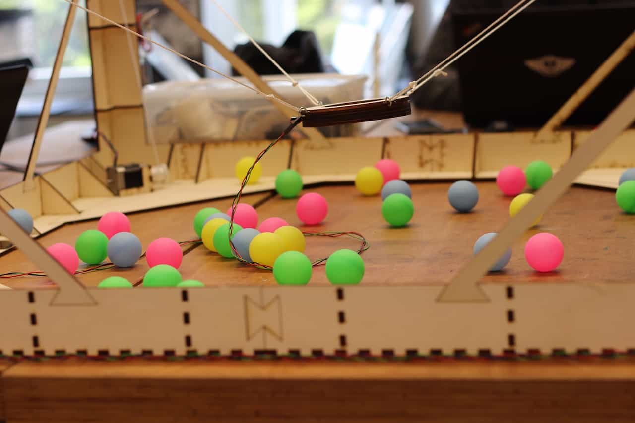
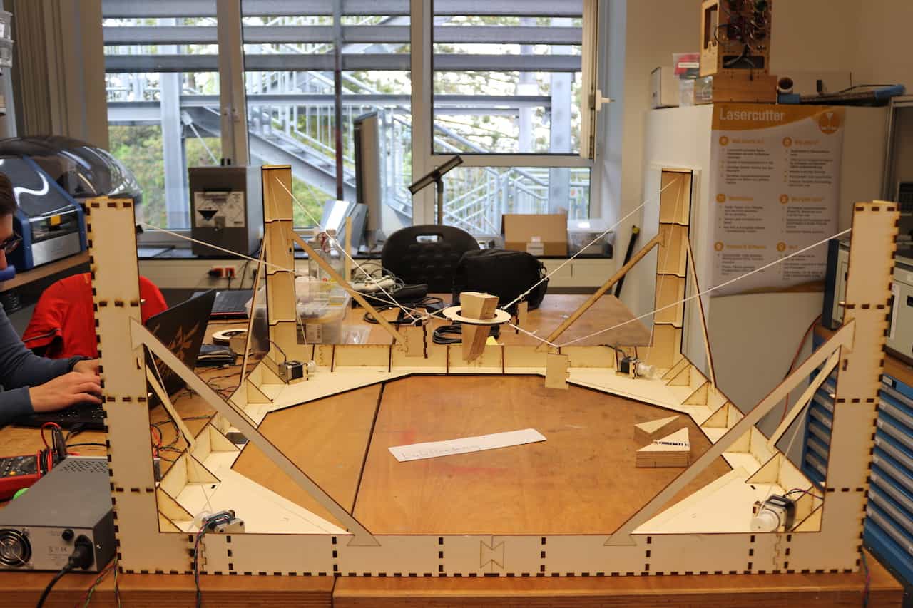
So we ended up with this SkyCam inspired design that you can see in the pictures. We had a few reasons for this decision: We expected it to be less precise than a normal 3 axis machine but for our application that is fine. The advantages, on the other hand, are: We expected it to be faster. It would be cheaper than the alternative because we would only use wood and ropes. And this design is easily extensible. You can easily make the frame bigger or even clamp the four base towers anywhere down and have a bigger space to play with. And even this frame is bigger than we could have created easily with the design from a Prusa. So with that settled we gave one part to everybody to work on and integrated everything together.
The Execution
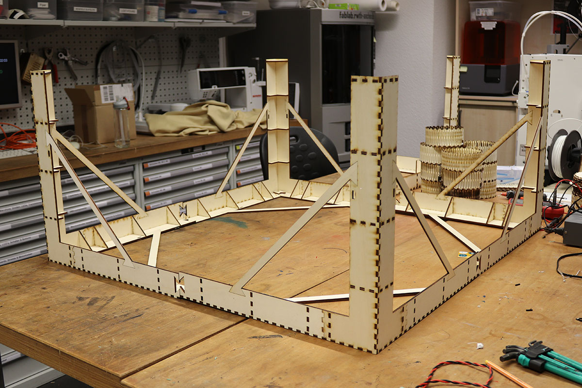
The Frame
As the base on which everything sits the frame is as important as the other parts. The requirements were to make it in the lab. Also, the frame should be sturdy and rigid, so that it does not wobble and move around when the ring is pulled somewhere. At last the frame should be quite big but small at the same time. It should span a wide area but consist of small parts so that you can see where you need to throw and that it doesn't block everything. It turned out really good and if you want to know more, check out Leon's documentation on how he designed and created the frame and what problems arose during it. He also designed the winches.
The Motors
We had to jointly control four stepper motors to move the sensor around. To this end, Christian designed, milled, and soldered a motor controller shield for an arduino that fits four Pololu A4988 stepper motor drivers. This way, we could connect the four drivers, four motors, and the arduino to a single 15V power source, and we only needed to program the arduino. The program samples a random position inside the frame, calculates the number of steps each motor has to move in order to move the sensor to the desired location, and finally moves the motors together. When a hit is detected with the sensor, another random position is sampled, and the cycle begins anew. To see more details on the control algorithm, visit Christians Machine Design page.
The Sensor
How the basic design came to live is described in Rene's assignment. In the Machine a few improvements had to
be made to the sensor, for example, the ring size had to be altered to make the more hittable.
Another small change was that we had to enhance the wall thickness to that we could attach hooks to the sides of the ring
to connect it to ropes.
We discussed attaching the cables to one of the ropes but that created more tangling than anything else, so we left it hanging down.
How does the sensor communicate with the other parts?
The sensor-code runs on the main controller so it has no microcontroller of its own. The Code simply checks for
the analogous value the photoresistor creates and when a certain threshold is reached the "Move Target code" is triggered.
Integration - Problems and Solutions
We had a few problems during integration due to various reasons.
One problem we had was that after putting the ring in place and wiring all the motors up with the rope the motors didn't move the ring as we expected. But this problem was not software related as we expected, instead we found out that one motor was the problem. And then we found that it wasn't the motor but just the cable we crimped ourself to the right length. One pin wasn't connected. Crimping this pin again and checking it solved the problem, but it was hard to find as we thought we would have checked the motors already.
Future Development Opportunities
- Adding more towers to make the ring constrained on all free axis so that we can tilt it as we want.
- Add LED's and a speaker for the real arcade feeling
- Paint everything
- Make a harder/cheat mode with cameras to track the ball and support the player
The Video
Files created this week
Winch
The winch fusion file
The winch stl file
Frame
The frame designed in openscad
The refined frame svg ready for cutting
Motors
Schematics for the motor shield board
Traces for the motor shield board
Motor test program (controllable via serial interface)
Sensor
Circle 1 and Circle 2
Test code for the sensor
Software
Final program (moves to a new random position after each hit)