This week we had to design our own circuit board and manufacture it. When something doesn't work you might want to use some kind of test equipment to see what's wrong. Next, to the very basic multimeter, the next best tool is an oscilloscope. We do have the Tektronix MSO 2024 in our lab. To test if the extended hello world board works, we changed the program to output the letter t on the serial port every 20ms:
while (1) {
   put_string(&serial_port, serial_pin_out, "t");
   delay_ms(20);
}
The code and makefile are also attached on the bottom of the page. To attach the oscilloscope to the board you connect the probe to the signal you want to observe (the RX pin) and the clamp to the ground pin.

Attaching the oscilloscope to the board
Then you can turn on the oscilloscope with the button in the lower left corner. Even if the oscilloscope has a lot of buttons at the first glimpse it is straightforward to get basic functionality. The drawback with our oscilloscope is that the rotary knobs are malfunctioning and therefore scrolling in one direction will scroll in random directions. So it is quite annoying to work with it. The buttons in the blue box are responsible for the trigger function. With that, you can adjust the level of the trigger. This triggers the recording and display of the following signal when the signal gets to the level defined by the trigger. Using the controls in the red box you can adjust the horizontal display of your signal. You can shift the signal to the side with the position handle, or change the scale of the axis. The controls in the green box do the same on the vertical axis. But with the menu button, you can hide/show the signal on this input probe. This is basically everything you need to use to inspect a periodic signal.
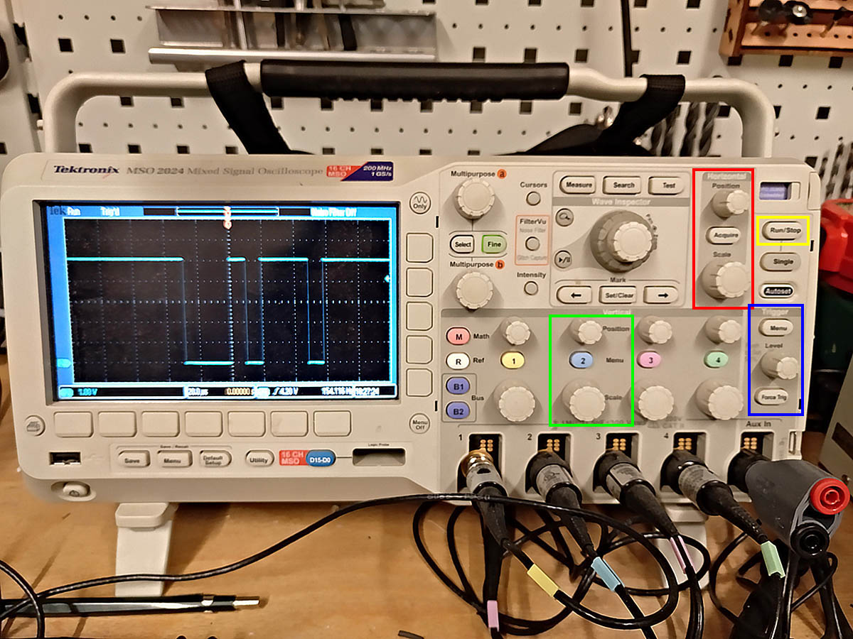
Using the oscilloscope
When you want to have a closer look at some data you can use the Run/Stop button in the yellow box. This will capture the data and display it. Then you can use the horizontal and vertical controls to zoom to the point of interest.
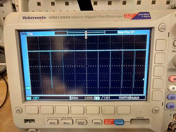
Signal zoomed out
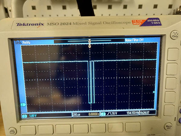
Zoomed in a bit
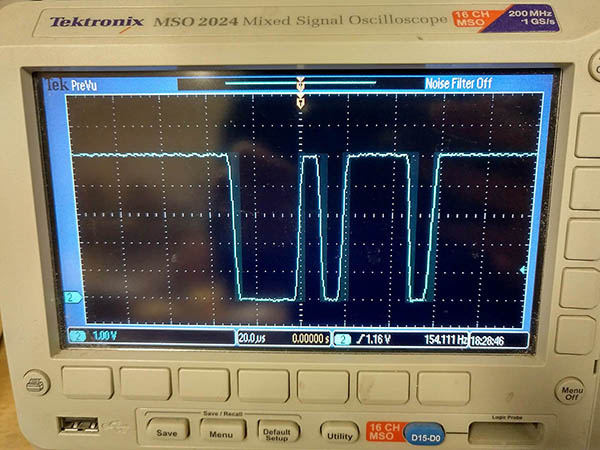
Zoomed in
In the above image, you can see that when you zoom in in a stopped capture you will have a rough representation of the signal if you zoom in very much. The original signal is a rectangle and the stopped and zoomed one is much more round.
All in all the oscilloscope is very useful if something doesn't do what you want and you want to see if the signals given are correct.