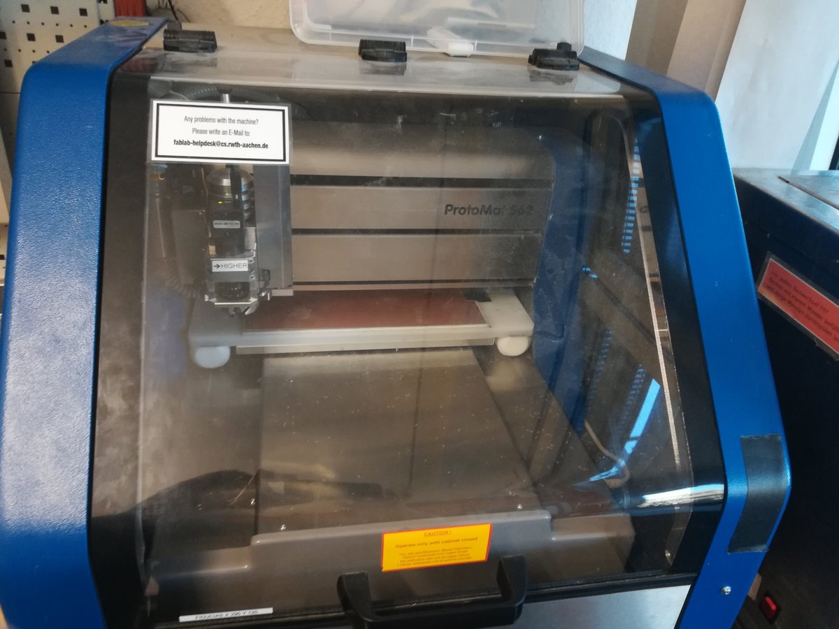
The topic of this week was the production of electronics, which means that we had to use a PCB mill to make our own circuit boards. As a group, we had to test the capabilities of our PCB mill. The mill in our lab is an LPKF Protomat S62 PCB, which is a professional milling machine; it is capable of producing two-sided PCBs and performing automatic tool change.
To make a board, we have to export our schematics and board layout using a CAM processor, then load it in CircuitCam, where we can preprocess it and generate paths for the mill, and finally use Boardmaster to drive the milling process.
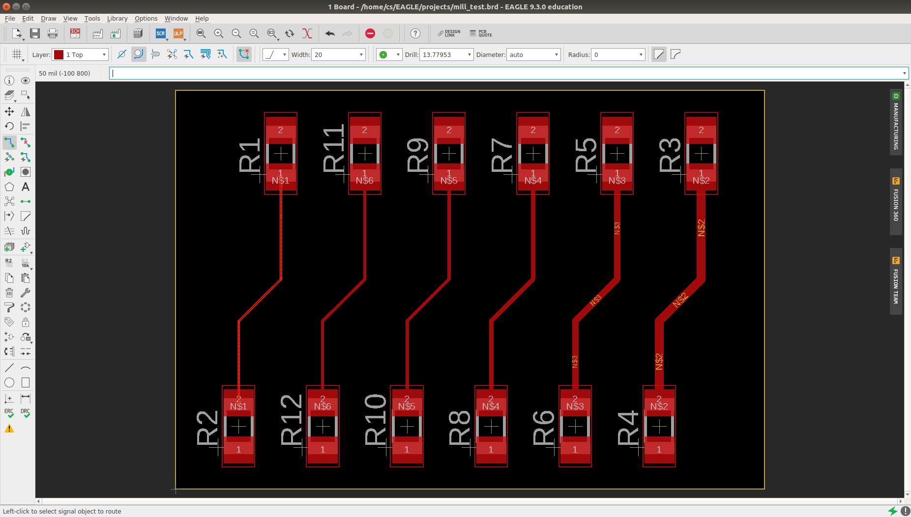
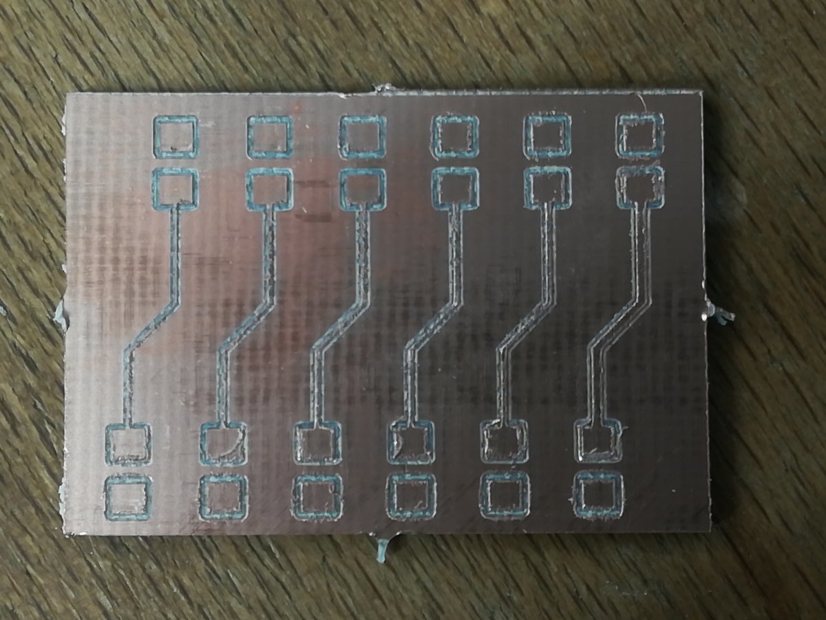
The layout consisted of routes of different widths. We tested widths of 4, 6, 8, 10, 15, and 20 mil. To inspect the milled board, we used the Optimaster 9000, which is a stereoscopic magnifier, a very handy tool when checking small components. We noticed that the smallest width seemed as if it was not properly milled. However, when checking with a multimeter, we found the two patches at the end still connected. Nevertheless, we think it recommended to use a width of at least 8 mil to ensure a proper connection and avoid accidental breakage of routes.
We noticed that wires, signals, and signal planes have to have a distance of at least the diameter of the smallest available milling bit to each other. For our PCB mill, that is a minimum distance of 8 mil, which is less than the standard 6 mil that is preset in Eagle. Also, the minimum drill diameter for vias and holes is 0.6mm, not the predefined 0.35mm. We gathered these specifications in an Eagle design rules file which can be used instead of the standard one to produce more consistent and reliable boards. It is available in the downloads below.