Shaper Origin
This week we had to work with a cnc mill, and we were able to use the Shaper Origin during this week. This is a computer controlled hand router, so you move the router by hand and the mill head can be controlled by motors, so it will do fine adjustments to stay on the path.
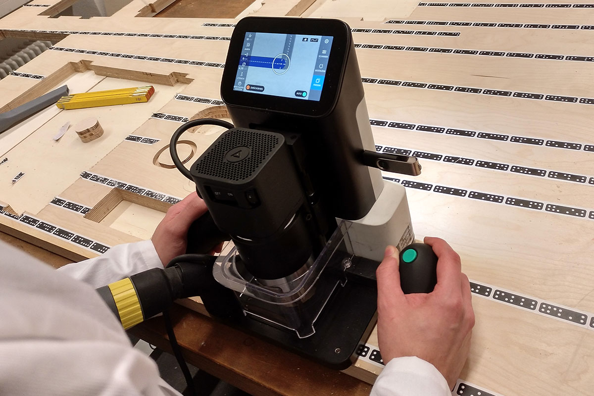
The Shaper Origin in action
Basic milling concepts
Let's go through some basic milling concepts and how they apply on this machine, which is not a traditional cnc mill because you also move it by hand. Make has a nice article explaining the basic concepts.
Differences between tools. There is a wide variety of tools available for all kinds of applications. As this is explained in this and this article I will just explain the different terms roughly. The tool can be straight or have an upcut or downcut spiral. The upcut spiral supports the chip removal, because the wood moves upwards in the spiral of the tool when it spins around. The downward spiral presses it down and the straight one doesn't do either. The next thing is the end of the tool, it can have a flat end, ball end or a v-shaped end. The flat end is great for cutting flat areas, the ball end when you want the lower side of your cut to be curved. The v-shaped one can be used for really small cuts, engraving or triangle shaped ones. We had a flat and v-shaped tool with the shaper and in the image below you can see the test cuts with both tools. Depending on the side on which your tool cuts on, in relation to the movement, the cutting motion is called conventional or climbing. Climb cutting pushes the bit away from the cut while conventional pulls it towards the cut. With cnc cutting usually climbing is preferred, because it causes less tearout. But the shaper uses the conventional cutting, because otherwise it would be really hard to control by hand, as it is constantly pushing itself away.
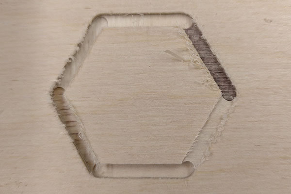
Test cut with different depth with a flat cutter
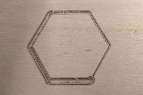
Test cut with different depth with an engraving cutter
Feeds and speeds. The feed rate is how fast you are moving the mill along the material and the spindle speed is how fast your spindle is rotating. This needs to be tuned to the material, as for example with too fast feed or speed you could leave burn marks in your workpiece, too slow and the edges of the cut could be ragged. With the shaper, you have a few different speed settings. We tested that the third with 16,400rpm worked the best with our workpiece and our feed. The feed with the shaper is a bit tricky, because you define the feed with your own hand movement. So it's not constant and you can't really tune it for any values. But you feel how fast you can go without too much effort.
Chip Load calculation. Chip load can be seen as the workload that is on each edge of the drill bit. It can be calculated as chip_load = feed_rate / ( spindle_speed * no_cutting_edges ). It is important to control this because this controls the tool wear, heat dissipation and also affects the surface finish. The chip load you should aim for depends on your tool and material, and typical values are 0.001-0.1 inch according to Neil or in more detail this website.