
Assignment :
individual assignment:design and build a wired or wireless network connecting at least two processors.
that you made.
send a message between two projects.
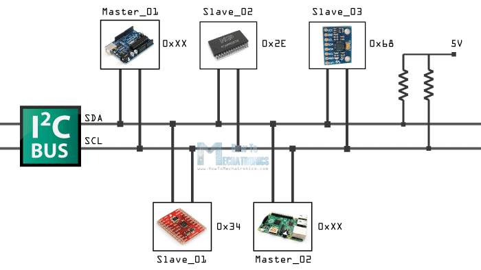
This week we have to create a network using our coustom PCBs . I decided to go for a wired protocole .I have used bluetooth before. So I wanted to learn I2c this time. I felt these are very useful while I am doing a modular project or while I needed to extent the pins of my microcontroller. Also a lot of I/O devices use these protocoles to minimizthe difficulty of hardware designing and minimizing the number of pins.
I2C was originally developed in 1982 by Philips for various Philips chips. The original spec allowed for only 100kHz communications, and provided only for 7-bit addresses, limiting the number of devices on the bus to 112 (there are several reserved addresses, which will never be used for valid I2C addresses). In 1992, the first public specification was published, adding a 400kHz fast-mode as well as an expanded 10-bit address space. Much of the time (for instance, in the ATMega328 device on many Arduino-compatible boards) , device support for I2C ends at this point. There are three additional modes specified: fast-mode plus, at 1MHz; high-speed mode, at 3.4MHz; and ultra-fast mode, at 5MHz. In addition to “vanilla” I2C, Intel introduced a variant in 1995 call “System Management Bus” (SMBus). SMBus is a more tightly controlled format, intended to maximize predictability of communications between support ICs on PC motherboards. The most significant difference between SMBus is that it limits speeds from 10kHz to 100kHz, while I2C can support devices from 0kHz to 5MHz. SMBus includes a clock timeout mode which makes low-speed operations illegal, although many SMBus devices will support it anyway to maximize interoperability with embedded I2C systems.
Because serial ports are asynchronous (no clock data is transmitted), devices using them must agree ahead of time on a data rate. The two devices must also have clocks that are close to the same rate, and will remain so–excessive differences between clock rates on either end will cause garbled data.
Another core fault in asynchronous serial ports is that they are inherently suited to communications between two, and only two, devices. While it is possible to connect multiple devices to a single serial port, bus contention (where two devices attempt to drive the same line at the same time) is always an issue and must be dealt with carefully to prevent damage to the devices in question, usually through external hardware.
Though SPI is good for high data rate full-duplex (simultaneous sending and receiving of data) connections, supporting clock rates upwards of 10MHz. It has some limitations.
The most obvious drawback of SPI is the number of pins required. Connecting a single master to a single slave with an SPI bus requires four lines; each additional slave requires one additional chip select I/O pin on the master. The rapid proliferation of pin connections makes it undesirable in situations where lots of devices must be slaved to one master. Also, the large number of connections for each device can make routing signals more difficult in tight PCB layout situations. SPI only allows one master on the bus, but it does support an arbitrary number of slaves.[learn.sparkfun].
For a better understanding of I2C protocole you can refer this sparkfun page.
I had some working boards from my last week Assignment. So I decided to do my networking assignment with my previously made boards.
But it was a terrible decision. All those wires made my mind freek. Since I didn't added pins for i2c i had to solder wires directly to the microcontroller pin . All those made my boards terrible and confusing .So I decided to mill a new PCB. I choose the satshakit micro and modified the PCB to connet multiple PCBs easly
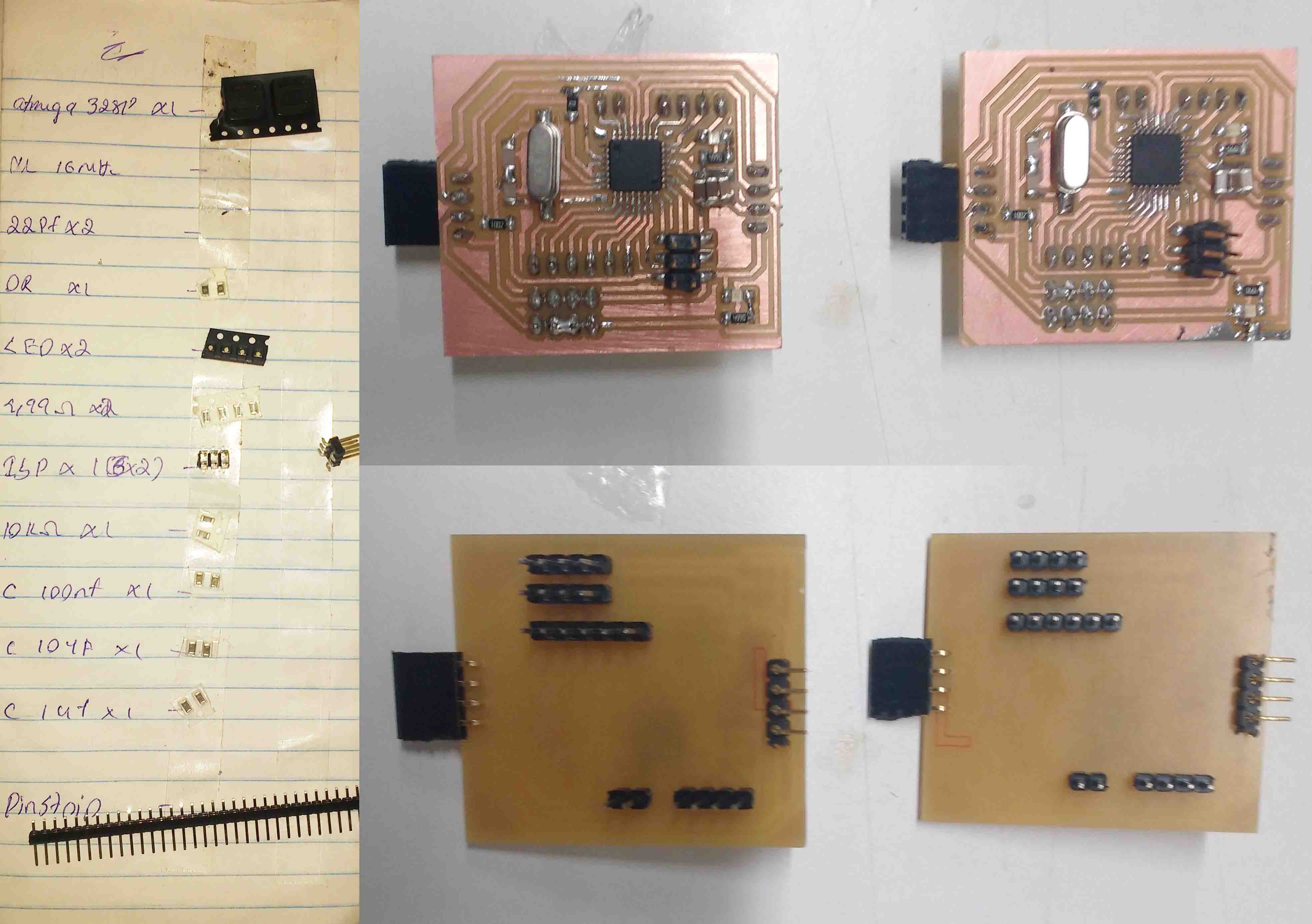
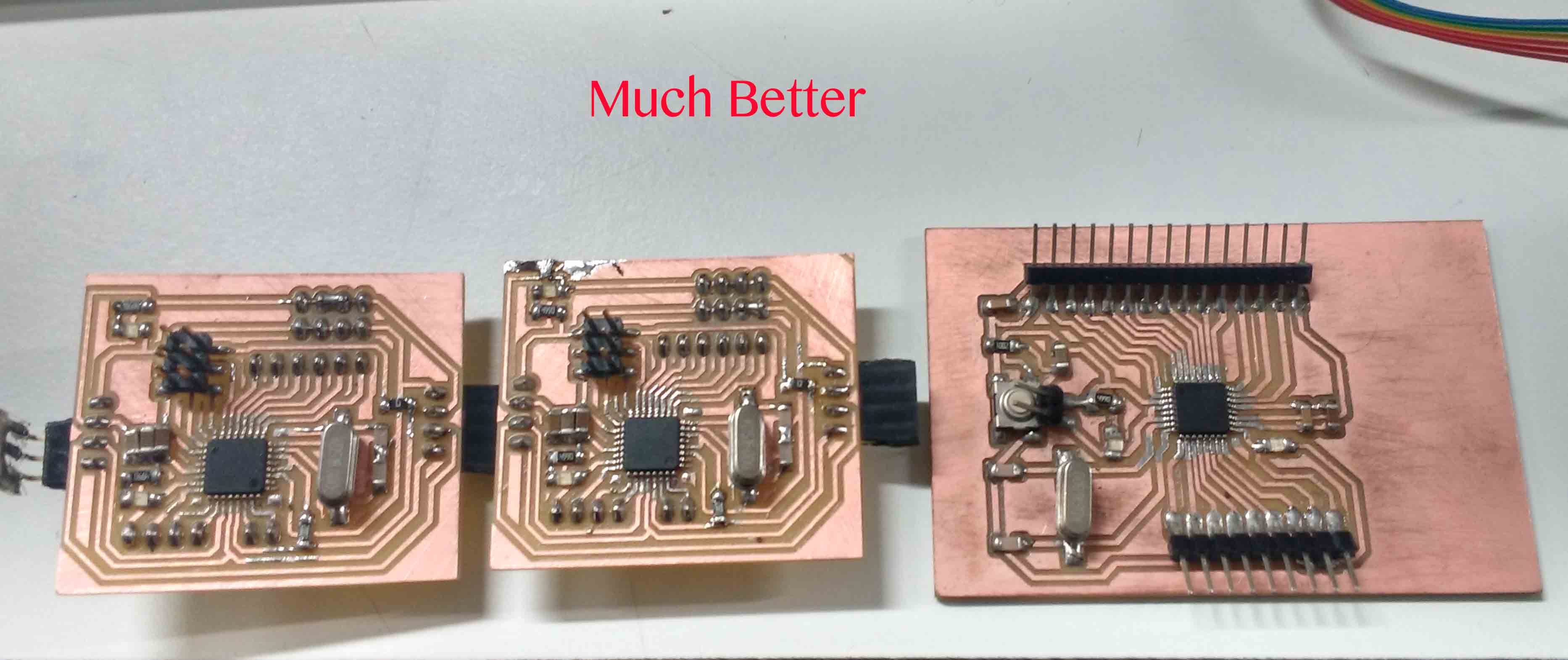
I placed the I2C ports at the both ends of the PCB so that I can add multiple PCBs to the network.
To complete my network I used one of my satshakit board I milled during my last assignment.
Remark I don't know why but while I uploaded my Bootloader It stoped in the middel I waited for a few minuts but it didn't responded. So I forced to remove it form my PC . But after removing it the board stoped to responde to the terminal , it shows thst "It can't connect to the device ".So I assumed that while I intrupted the uploading it might have altered some fuse settings. Since we didn't had any High voltage programmer I forced to replace my Microcontroller.Now everything works fine.
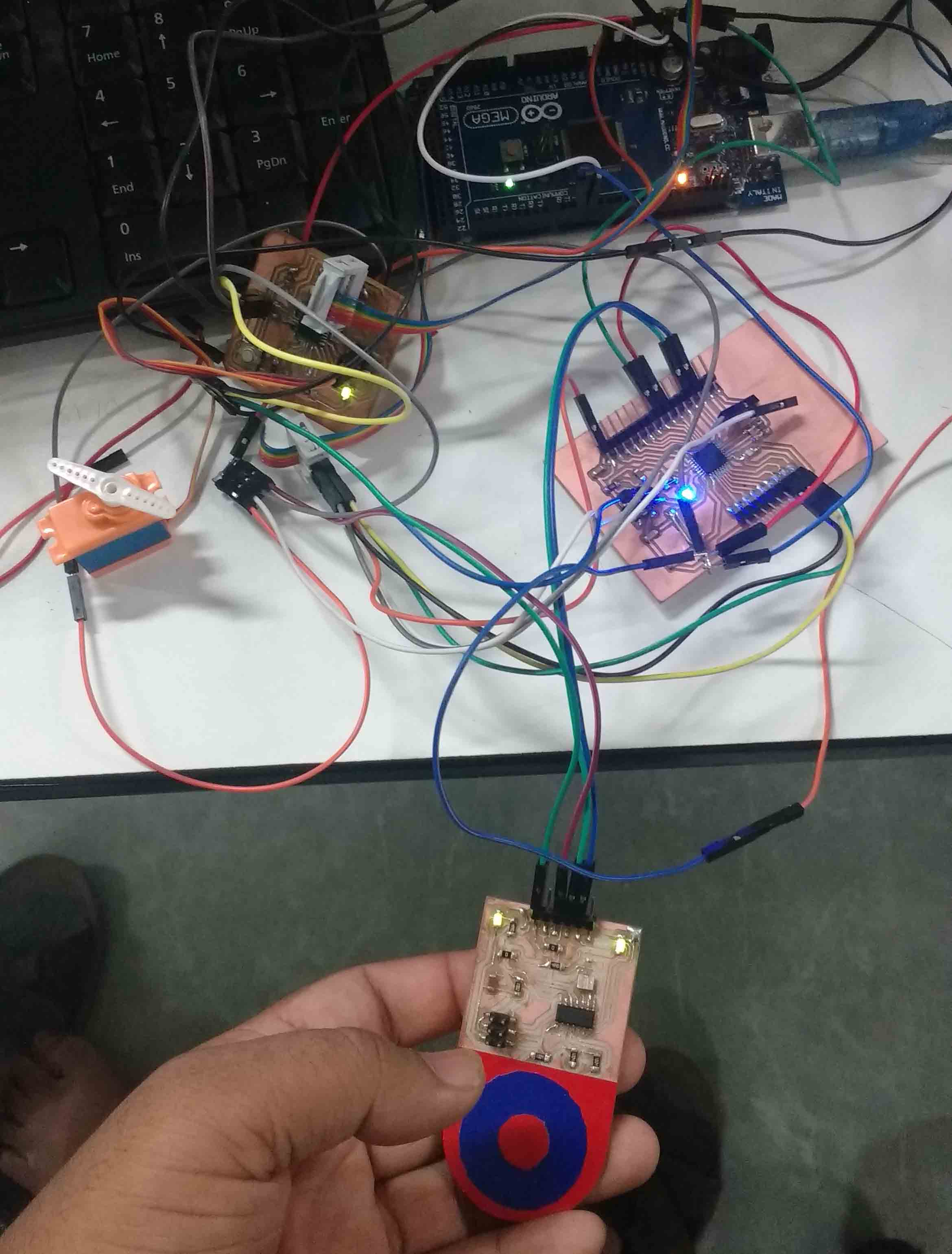
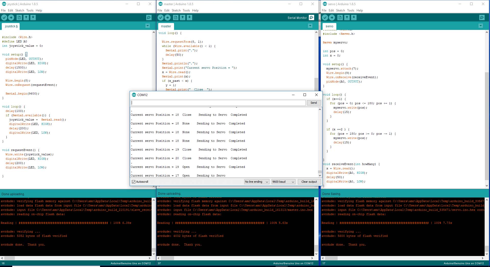
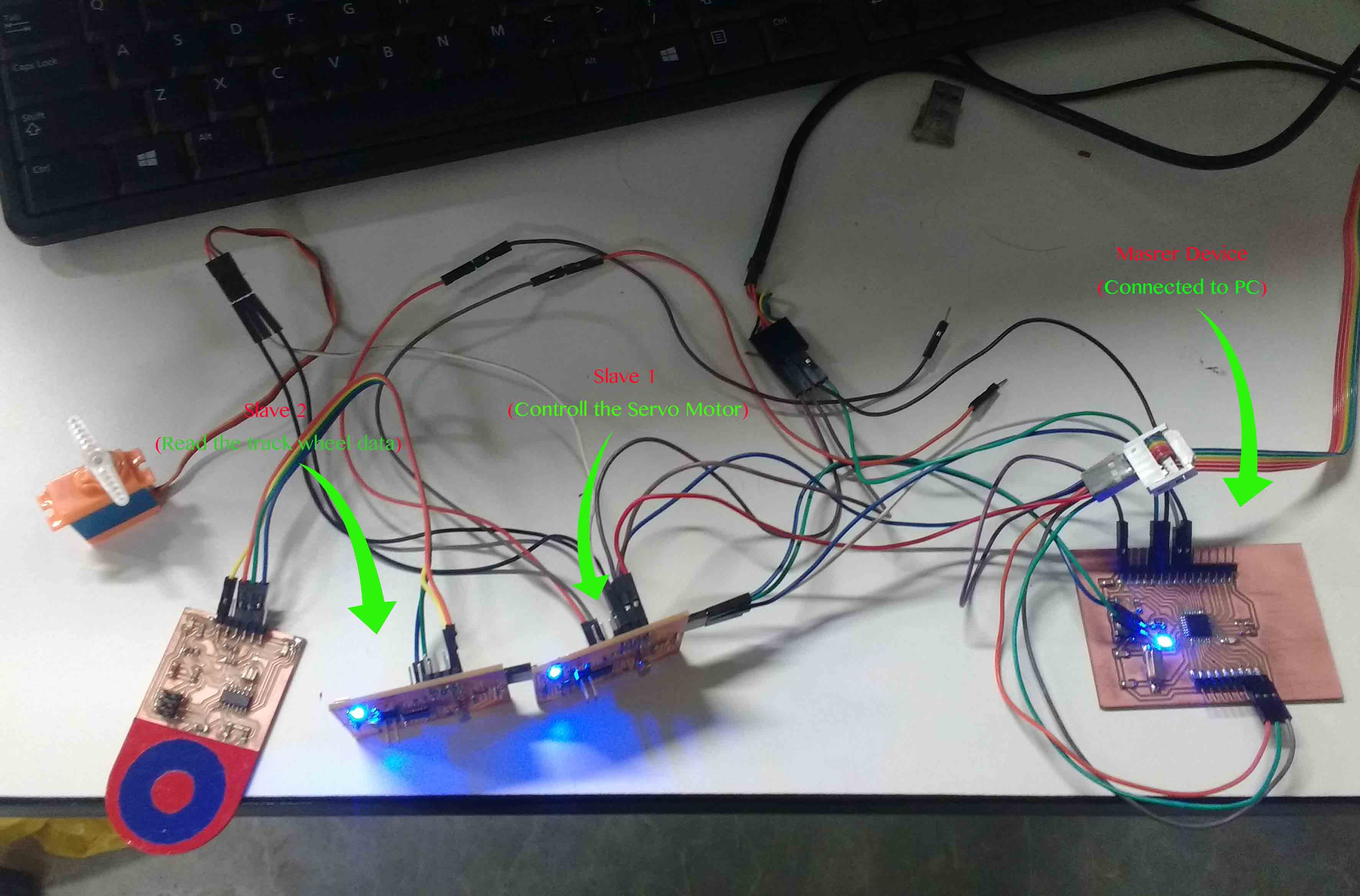
What i wanted to implement is , While I rotate my capacitive scroll wheel which is connected to the 1st MC board the servo motor attached to the second board will rotate also the 3rd board which also serves as the master board wiil send the data to the Pc and will display it .
So I had to program 3 boards
1st I had to program the board which reads from the capacitive scroll wheel.
This is a simple arduino program which read the serial data and send it to the master when the master demands(Slave send date).
#include <Wire.h>
#define LED A0
int joystick_value = 0;

void setup() {
  pinMode(LED, OUTPUT);
  digitalWrite(LED, HIGH);
  delay(1500);
  digitalWrite(LED, LOW);
  Wire.begin(8); //Wire address
  Wire.onRequest(requestEvent);

  Serial.begin(9600);
}

void loop() {
  delay(100);
  if (Serial.available()) {
    joystick_value =  Serial.read();
    digitalWrite(LED, HIGH);
    delay(200);
    digitalWrite(LED, LOW);

  }
}

void requestEvent() {
  Wire.write(joystick_value);
  digitalWrite(LED, HIGH);
  delay(200);
  digitalWrite(LED, LOW);

}
Next I need to program the board which controlls the servo motor. This is also an event driven program. When a wire data is received it updates the value of variable "x". By refering the value of "x" the loop changes the position of the servo motor.(Slave receive data)
#include <Servo.h>
#include <Wire.h>
#define SERVO 7
#define LED A0

Servo myservo;
int x = 0;
int pos = 0;

void setup() {
  myservo.attach(SERVO);
  Wire.begin(9);
  Wire.onReceive(receiveEvent);
  pinMode(LED, OUTPUT);
}

void loop() {
  if (x == 1) {
    for (pos = 0; pos <= 180; pos += 1) {
      myservo.write(pos);
      delay(15);
    }
  }

  if (x == 2 ) {
    for (pos = 180; pos >= 0; pos -= 1) {
      myservo.write(pos);
      delay(15);
    }
  }

}
void receiveEvent(int howMany) {
  x = Wire.read();
  digitalWrite(LED, HIGH);
  delay(50);
  digitalWrite(LED, LOW);
}
The last one is the master device .Here the master has to receive data from the 1st board(slave read) and write the corresponding servo position to the second board(slave write).In the same time master has to upadate the values to the PC also.
#include <Wire.h>
#define LED 13

int x = 0;
int x_past = 0;
int y = 0;

void setup() {
  Wire.begin();
  Serial.begin(9600);
  Serial.println("Starting I2C");
  pinMode(LED, OUTPUT);
}

void loop() {

  Wire.requestFrom(8, 1);
  while (Wire.available() < 1) {
    Serial.print(".");
    delay(50);
  }
  Serial.println(".");
  Serial.print("Current servo Position = ");
  x = Wire.read();
  Serial.print(x);
  if (x_past < x) {
    y = 1;
    Serial.print("  Close  ");
  }
  if (x_past > x) {
    y = 2;
    Serial.print("  Open  ");
  }
  if (x_past == x) {
    y = 0;
    Serial.print("  None  ");
  }
  digitalWrite(LED, HIGH);
  delay(200);
  digitalWrite(LED, LOW);

  Serial.print("  Sending to Servo");
  Wire.beginTransmission(9);
  Wire.write(y);
  Wire.endTransmission();

  delay(1000);
  Serial.println("  Completed");
  x_past = x;
}
Upload all the programs to the corresponding microcontrollers.
You can download all related Files Here