
My final project is an IoT controlled irrigation valve .The valve could turn on and off the water supply to different parts of an aggricultural land.The system is completely relaying on solar power and also it could be operated using an android app.
I planned to use some of the processes we have learned during our weekly assignments.
This is a small sketch which I have made during my 1st weekly assignment.
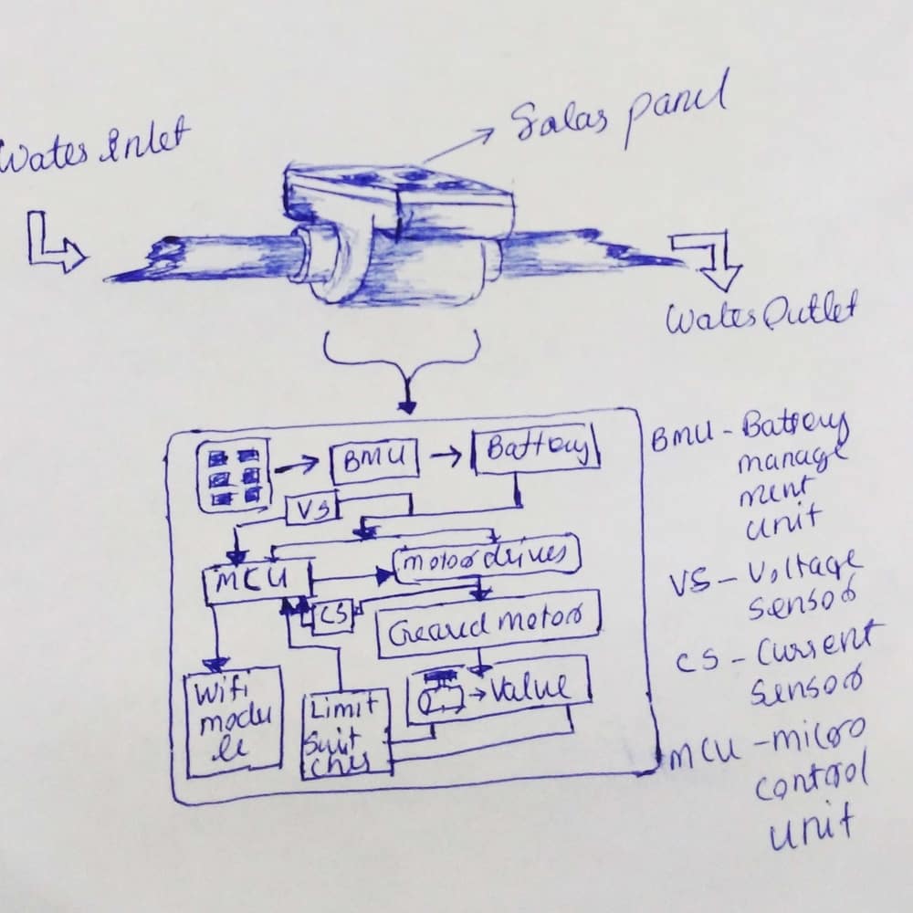
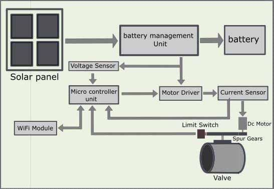
This is how I planned to complete my electronics.
I created a "to do" list in trello. and this is how I planned to complete my project.

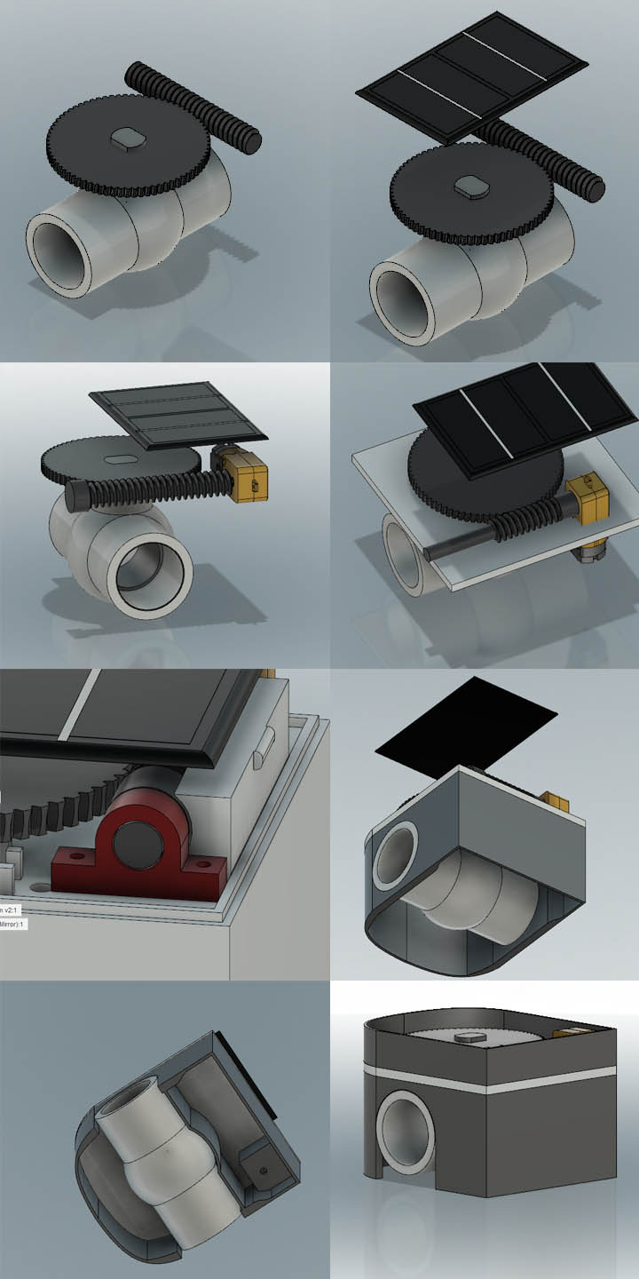
I used Autodesk Fusion 360 to design my project. To start my project initially I created a library of all commercially available components I needed for my project.Then I added components to the Work and arranged them in a proper way..
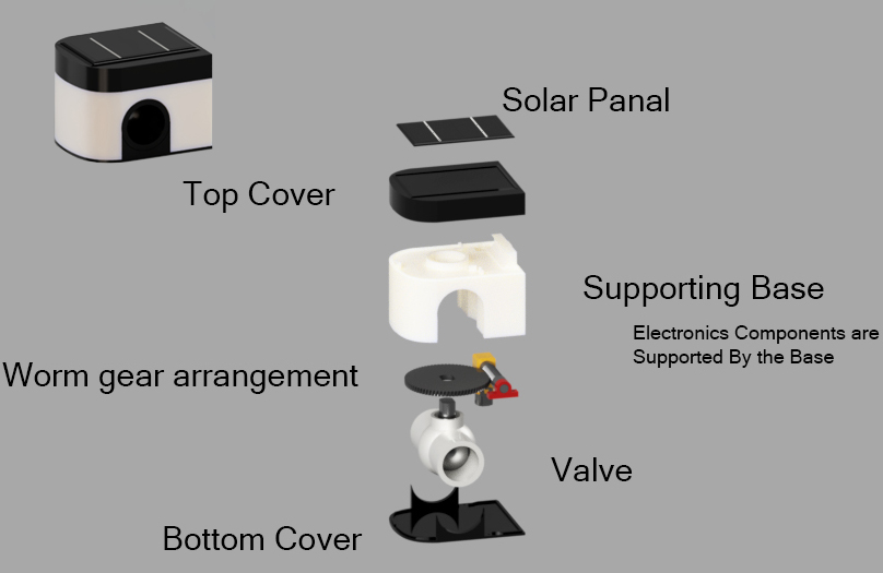
I made the enclosure as 3 different parts .A base which support all the mechanical and electronics parts,A bottom cover to hide the bottom portion also protect the battery and electronics from external enviournment factors,A top portion to support the solar panel and also for protecting the motion mechanism.
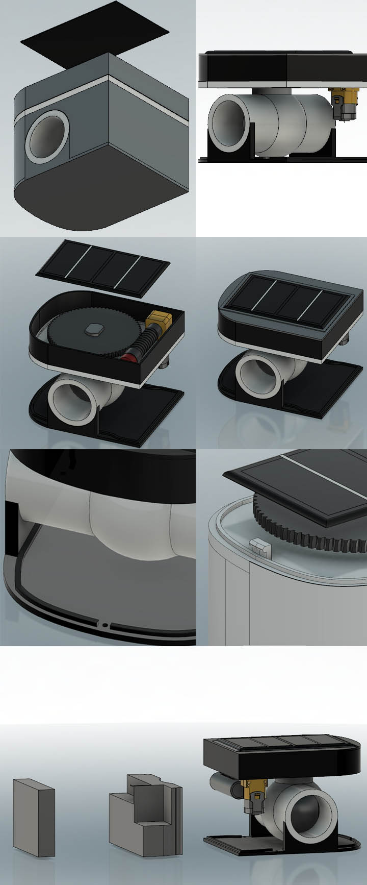
To design my PCB I had to find out the space I could use for placing my PCB .So 1st I created a model of my available free space.Next i created a rectangular space were I could place my PCB.I created a sketch on the top of the rechangular block and projected my available space geometry to it .then I exported my sketch as a dxf file and imported the same geometry in an eagle document to arrange my pcb.
Finaly I created a supportung Structure for limit switch and some holes for wire management.
Completed CAD design.
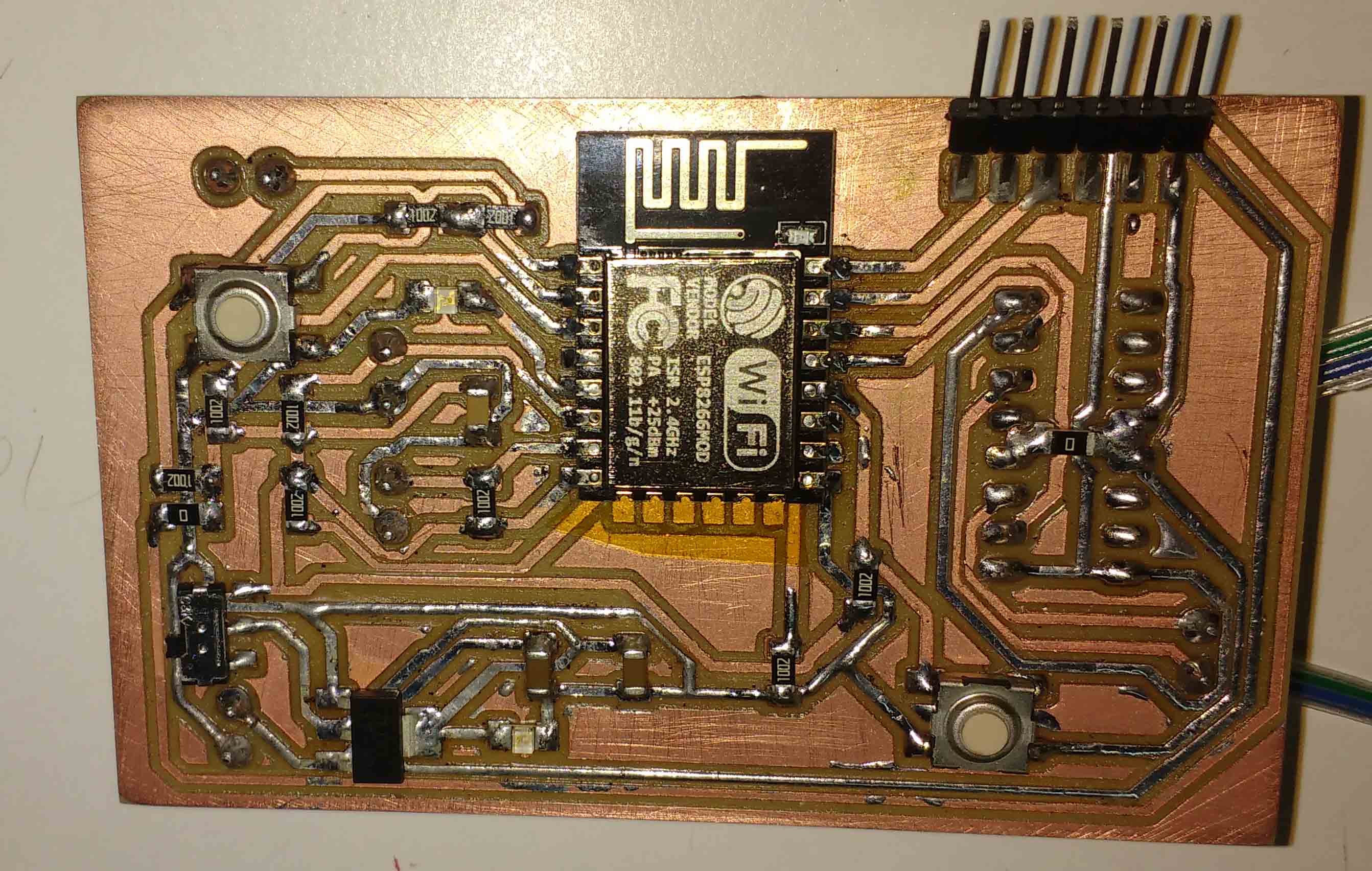
I used esp8266 as my processor .The ESP8266 WiFi Module is a self contained SOC with integrated TCP/IP protocol stack that can give any microcontroller access to your WiFi network. The ESP8266 is capable of either hosting an application or offloading all Wi-Fi networking functions from another application processor. Each ESP8266 module comes pre-programmed with an AT command set firmware.
Currently ESP is the most suitable platform for me It provides intergated wifi and onboard microcontroller. So I don't have to add another microcontroller.
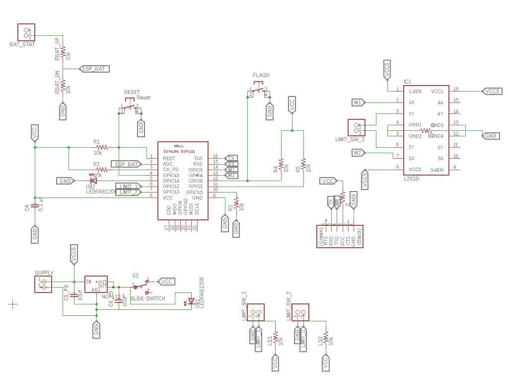
For driving my motor I used the L293D dual H bridge motor driver IC.
In addition to the motor driver and soc I added a 3.3v regulator ,2 push button each for reset and flash,A potential divider circuit for cell voltage measurement.I added 3 ports 2 for connecting 2 limit switches and a ftdi port.
This is the completed schematics in eagle.S
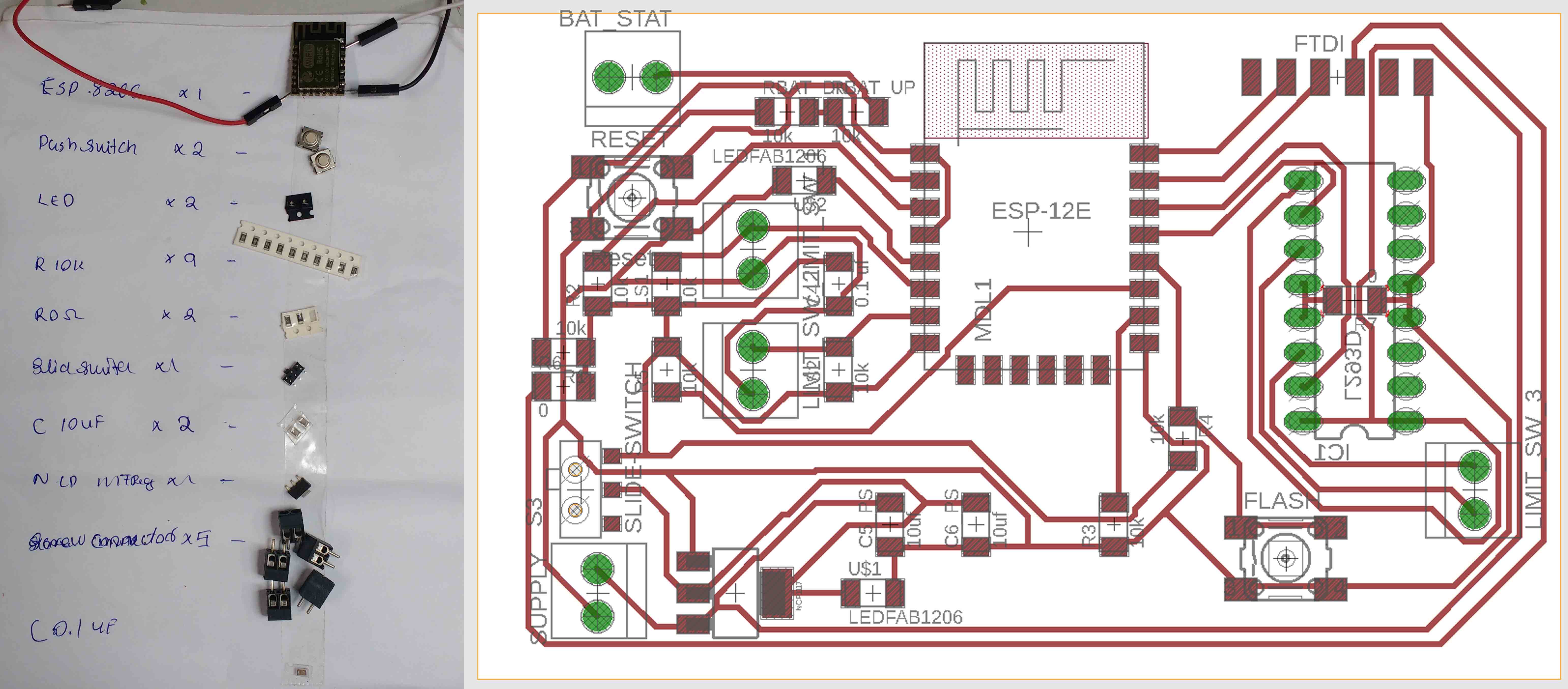
I used the dxf file I exported from fusion to create the boundary for my pcb .I arranged everything in the available space and completed my pcb.
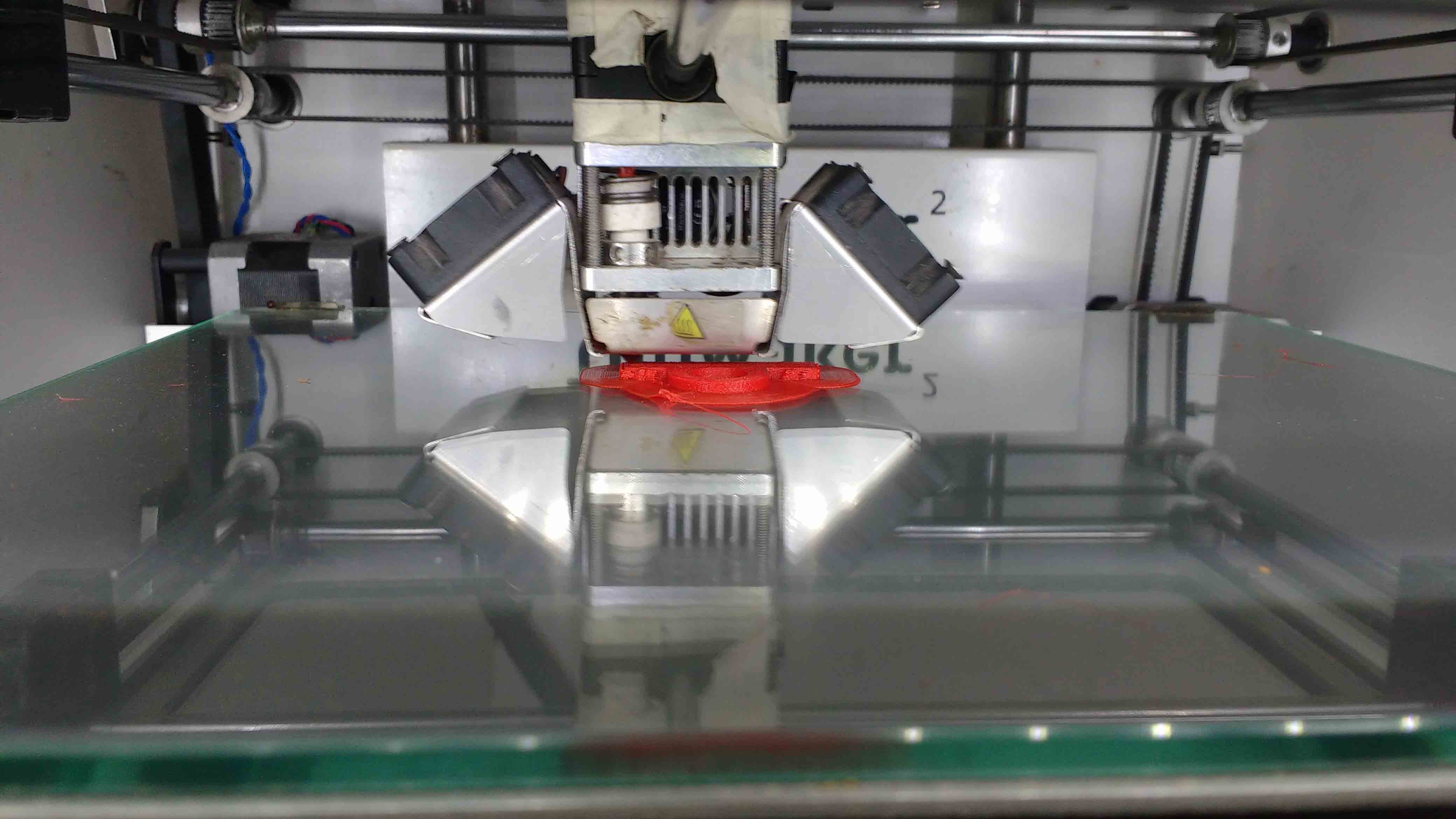
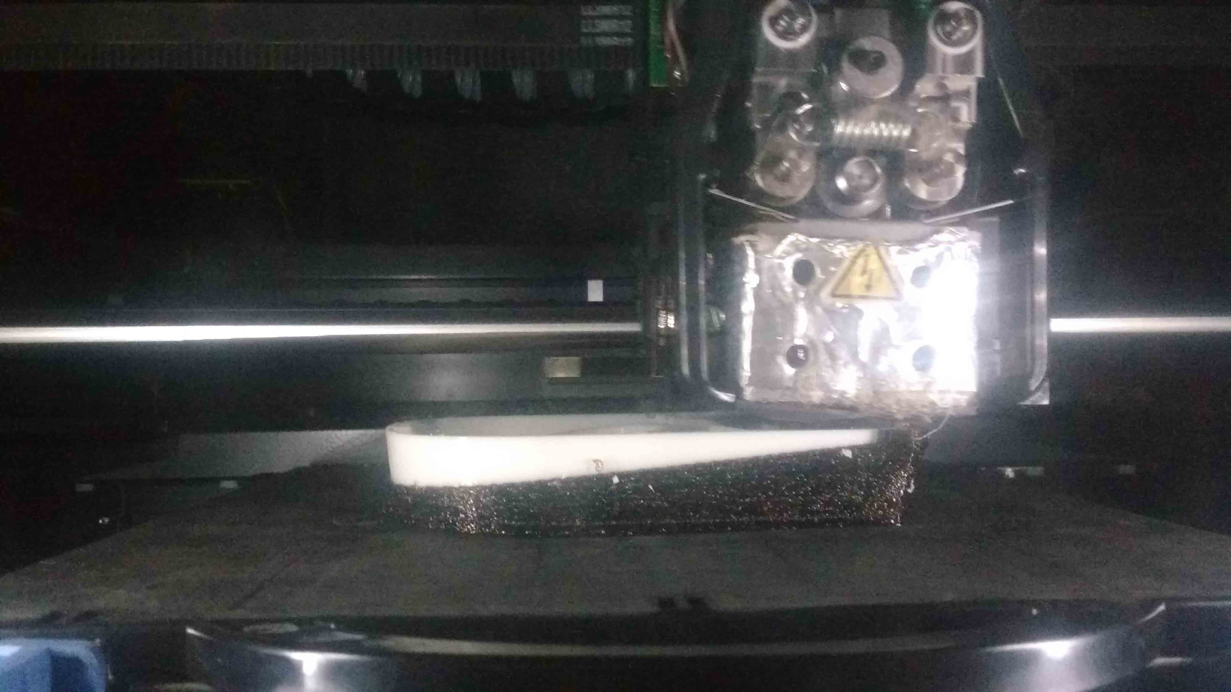
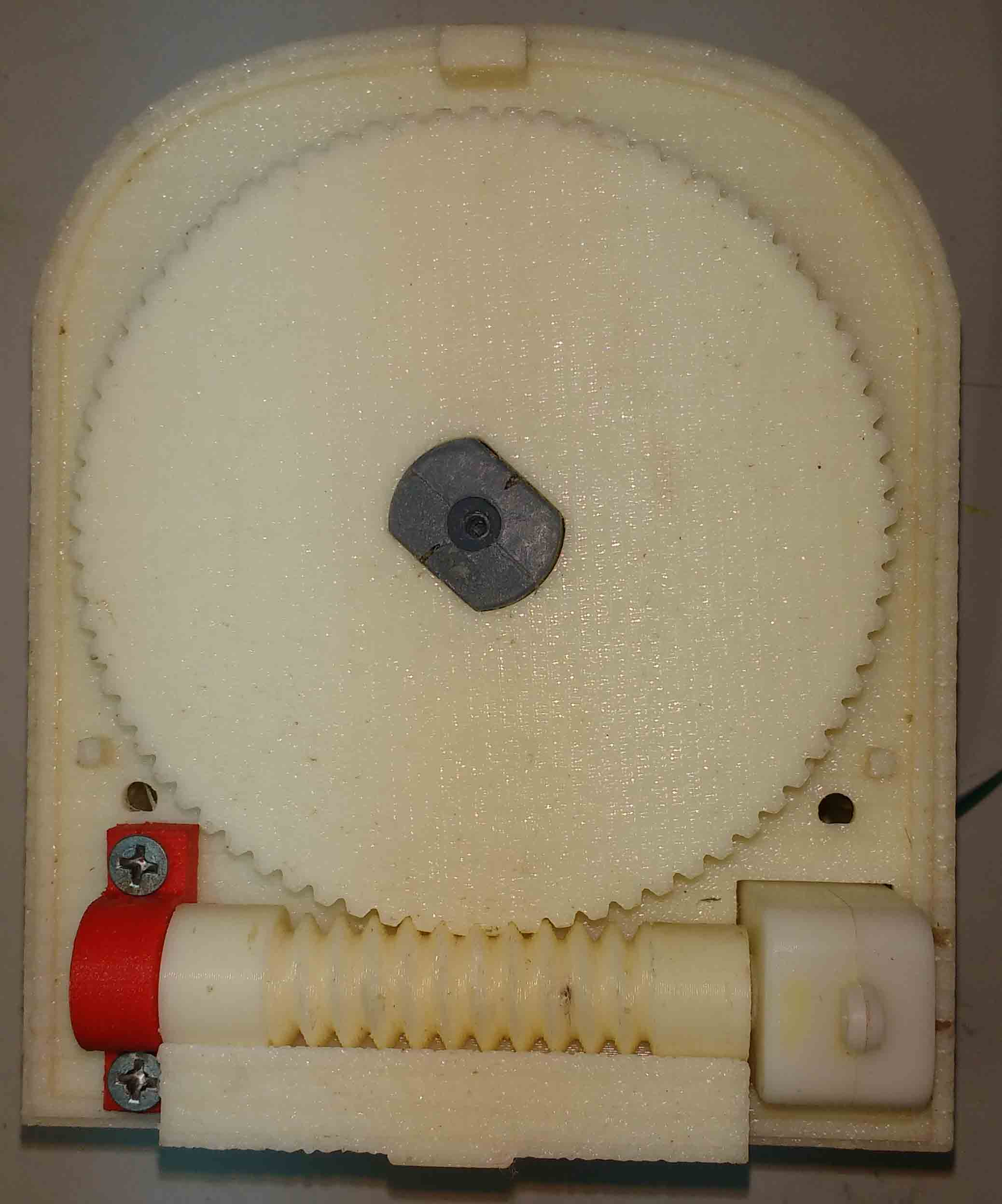
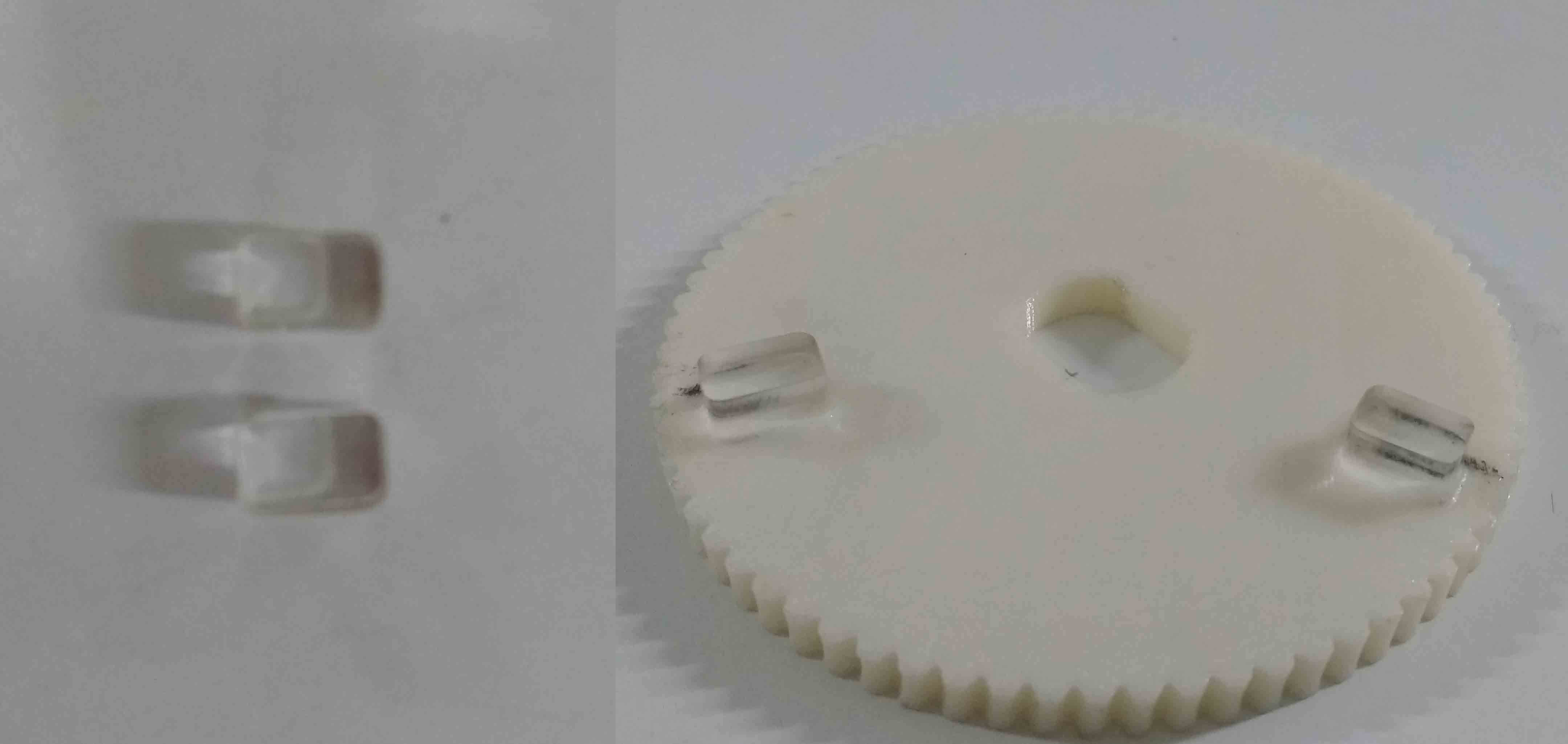
Since i needed a strong support structure to support the worm gear and motor mechanism . I decided to Print the base , worm gear and helical gear with dimension sst 1200es 3D printer.Also i planned to use ultimaker for printing the top , bottom covers and the worm gear support.
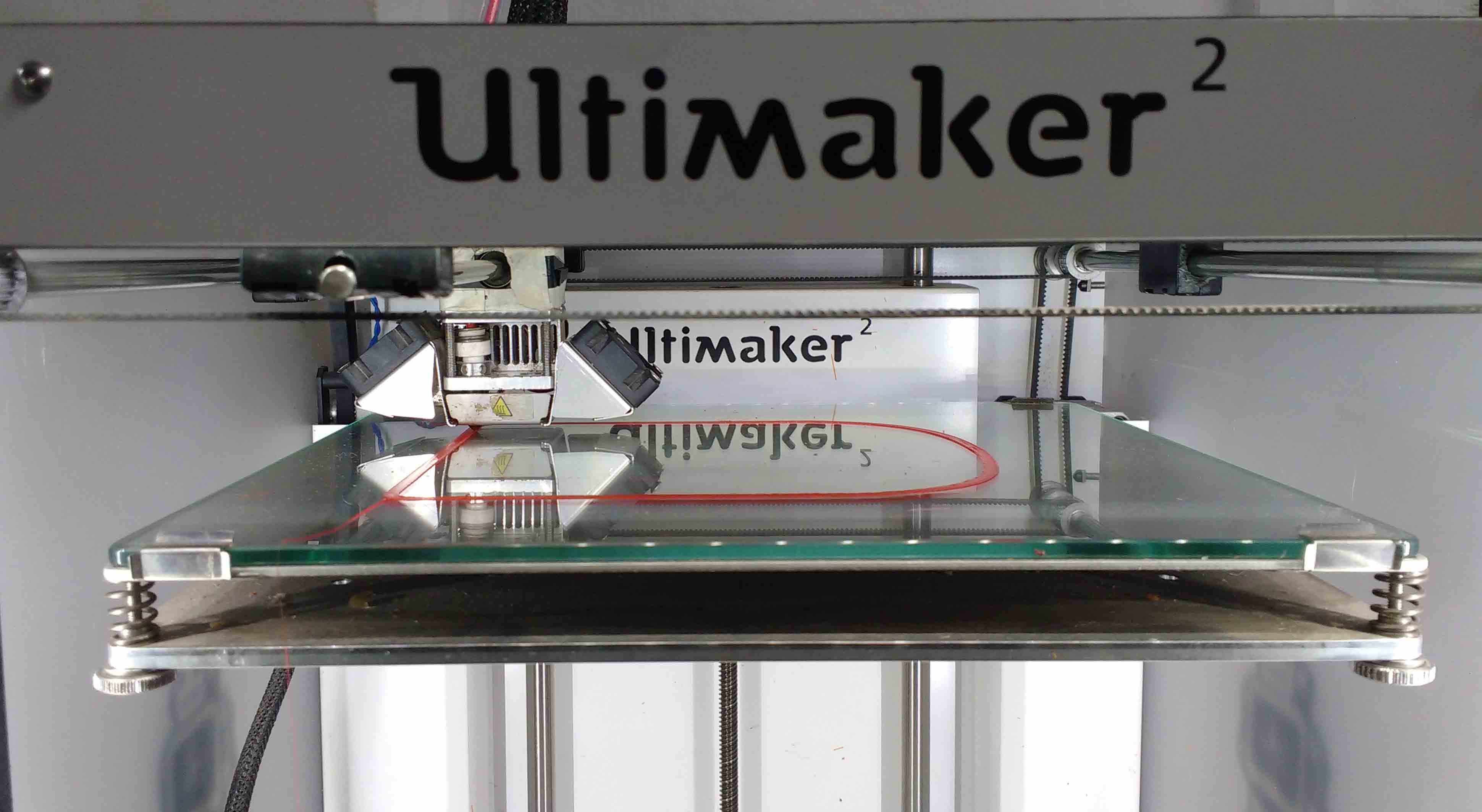
I also printed the support structure for the worm gear in ultimaker.
Dimension printing my base structure.
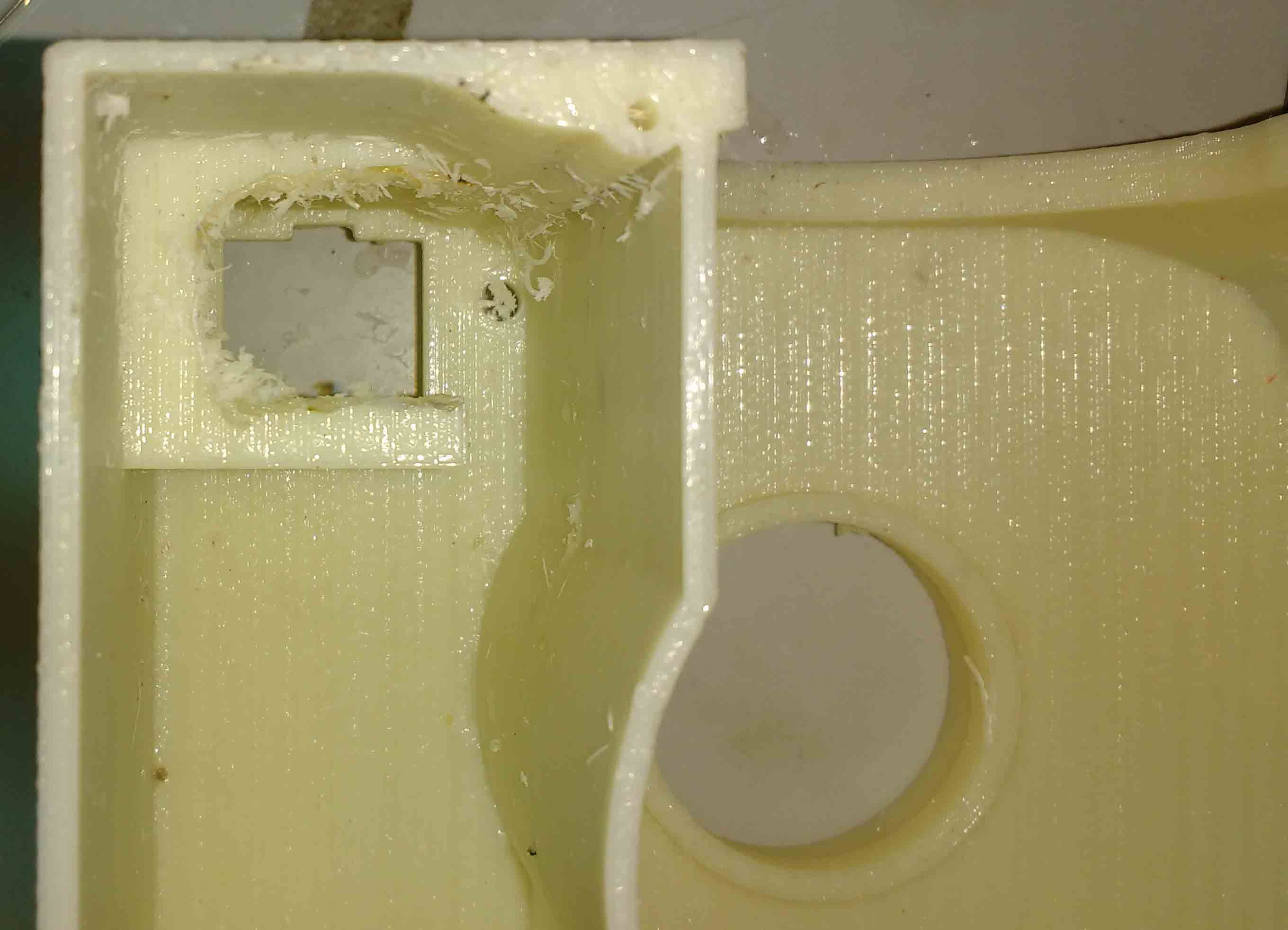
Mistake Though I designed with much patients .I had to change the motor which used during my designing. Unfortunately the new one was a little longer than the previous one. So I had to cut the bottom support of my mottor on my base plate.
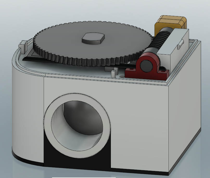
This is the assembled motion mechanism.
I could have avoided laser cutting .But I couldn't able figureout were to put the limit switch blocks. Because unfortunately my valve doesnot have the same force to rotete at every point. I had to choose the minimum friction quarter to function it properly. So I laser cutted them and assembled them after completing the motion platform so that I could adjuest the limits if the motor can't rotate them at that position.
I made my PCB with Modela MDX20 CNC milling machine I used 1/64 inch V bit for tracing and 1/32 bit for milling and drilling.
For the soldering process 1st I created a list of electronics components I needed .Then place a double side tape next to the table . I arranged all the required components in the tape and started my soldering.
Since I had components on the both sides of the board for easiness I initally soldered the SMD components and then soldered the through hole components .If i were soldered the through hole components 1st I might have faced difficulty to place the board stably on a platform to solder the SMD components.
This is the PCB after fabrication.
The solar panel I decided to use will generate 5V and 81 mA / panel. I decided to use 2 of them so that I will get a total of 162 mA (total 2x81 = 162 mA).Since the solar energy may vary over time. Depending on the availability of sunlight I can't completely relay on solar energy to drive my system. I must have to add some storage mechanism to store excess energy and use them while the valve rotation tooks place.
I need to check wether I could get enough energy from solar to work my device .So I decided to do some calculation.
Initially I decided to took some readings from some online resources to check the feasibility
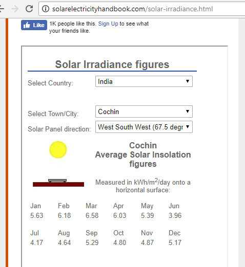
This is the availibility of solar power in our city kochi. The maximum solar energy receving in a horizontally placed panel of area 1 m2 in a day in june is 3.96 .
The typical efficiency of a small solar panel is arround 12 % (I got it from solarmango.com)
Since I am using a 6.5 cm x 10 cm the amount of energy it could be generated in a day is.
Energy = Area of panel m2 x 3.96 x (12% / 100)
so Energy = (0.065 m x 0.1 m ) x 3.96 x 0.12 = 0.0028782 kWh = 10361.52 Jule
From theory I could have collected 10361.52 Jules in a day.But It will be depending on the efficiency of my charging , boost converter circut and solar panel .Also the charger may stop if the terminal voltage of my solar panel falls below a threshold value.So it may vary in reality.
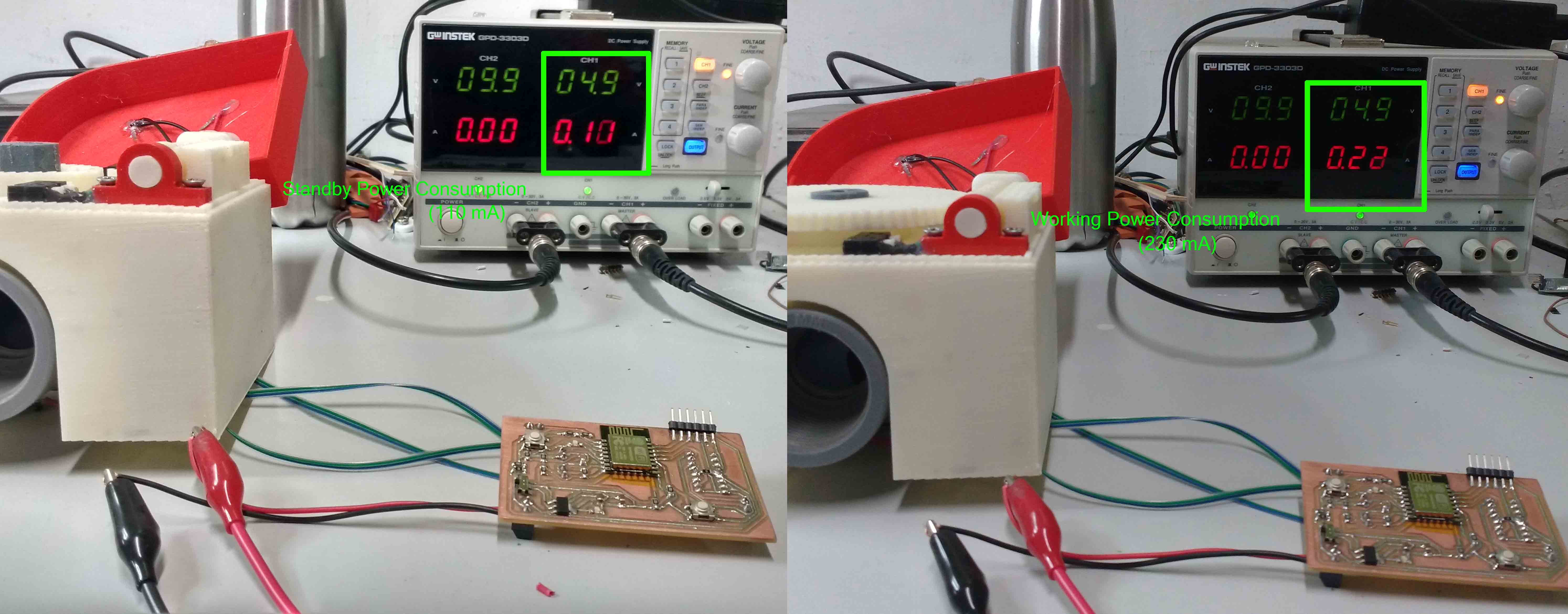
From testing my board I found that the stand by current I needed for running my valve is arround 110 mA at a voltage of 5V . When I was using the motor to turn on and off the valve the current consumed were raise to 220 mA at 5v.
So the energy I required to work for 24 hr In stand by mode is
energy =IxVxt = .11 x 5 x 60 x 60 x 24 = 47520 J
The energy I required to turn off or on the valve is(it took 30 seconds to turn on or off )
energy = IxVxt = .22 x 5 x 30 = 33 Jule
Next I have to physically test my pannels.
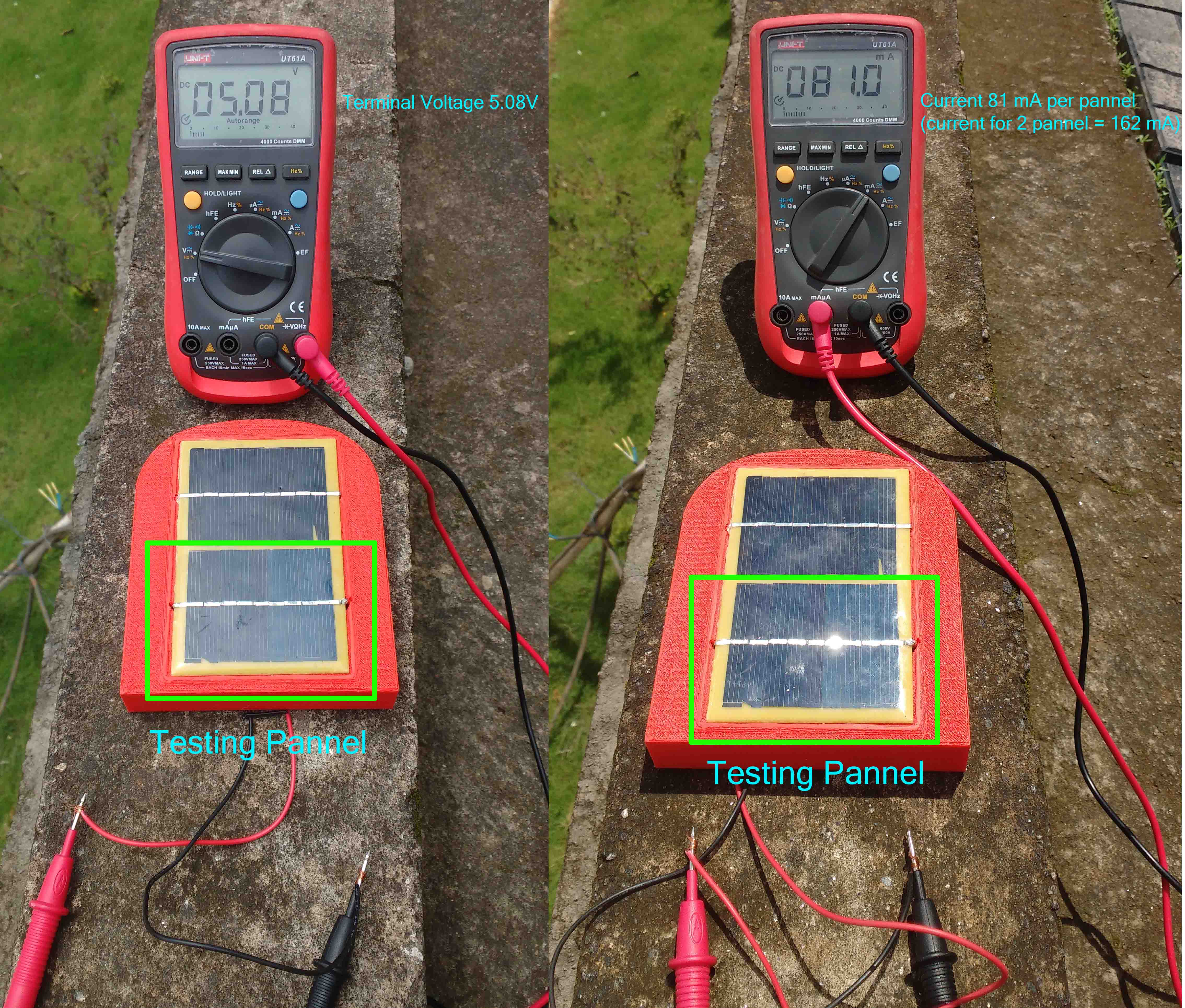
I found that during the peek hours I gets 5.08v at 162 mA(from 2 panels) from my solar panels.
The figure below shows the avalibility of solar energy in a day . Fom that we can say that the total solar energy could be converted can be written as = peek sun hours x peek output.
Typical peek sun hours in kerala is 5 hours . So possible energy/day = (.162 x 5) x (60 x 60 x 5) = 14580 Jule (We have got 10361.52 Jule during calculation from online data so this is an acceptable data.)
If I need 33 jules for turning on and off my valve.So I could have done (14580 / 33) 441 turn on and off / day with the available sun light .
Problem But currently I am using my board in access point mode so I can't use power saving mode for now . The board consumes an enormous 47.52 KJ/day .If I am going to use ESP in this way I might need a solar panel of 3x of my current area .So for my future developmets I decided to use Bluetooth low energy .But to complete my fab project I am using ESP for now .
The solar panel producess 5 V but the terminal voltage of my Li-ion cell is 3.7v So to charge my cell by maintaining the charging current I need to have a battery charging circuit . Normaly Li-ion cells have a very low internal resistance so if we apply a higher voltage a large current may flow and the I2Rt heat loss may damage our cell .So usually we needs a charging circuit for controll the current . But since my solar panel only produces a maximum current of 162 mA I thought It won't be a problem for me . But when I searched the web there were a lot of people using a charging circut .Don't know why but due to that I also decided to use the charging circuit.
Earlier I was planning to create a charging circut of my one using the SoC itself.The soc will read the current using a series resistor and controll the current with a mosfet . But later I found thet time is limted and also ESP only have a single analog pin which I had to use for reading the Battery Charge status.So I forced to buy two module one for the battery management and another for boost comverting(3.7v to 5v) .I needed a boost converter to produce a 5V for my motor and L293d motor driver.
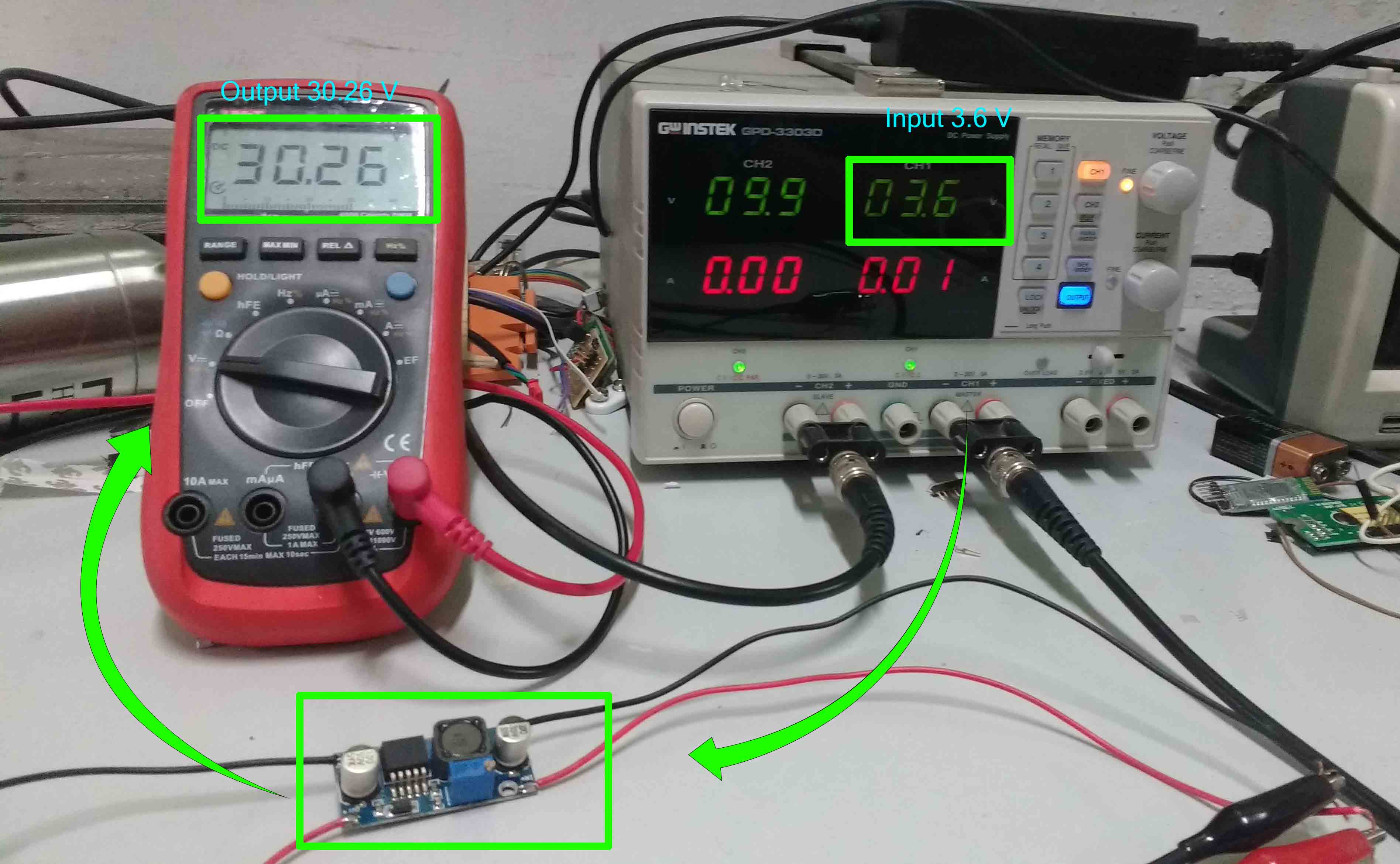
I used tp4056 module for cell charging(5v to 3.7v) and LM2596 DC-DC Buck Converter for bosting the voltage form Li-ion cell's 3.7 volt to 5v.The image shown below is the LM2596 DC-DC Buck Converter module
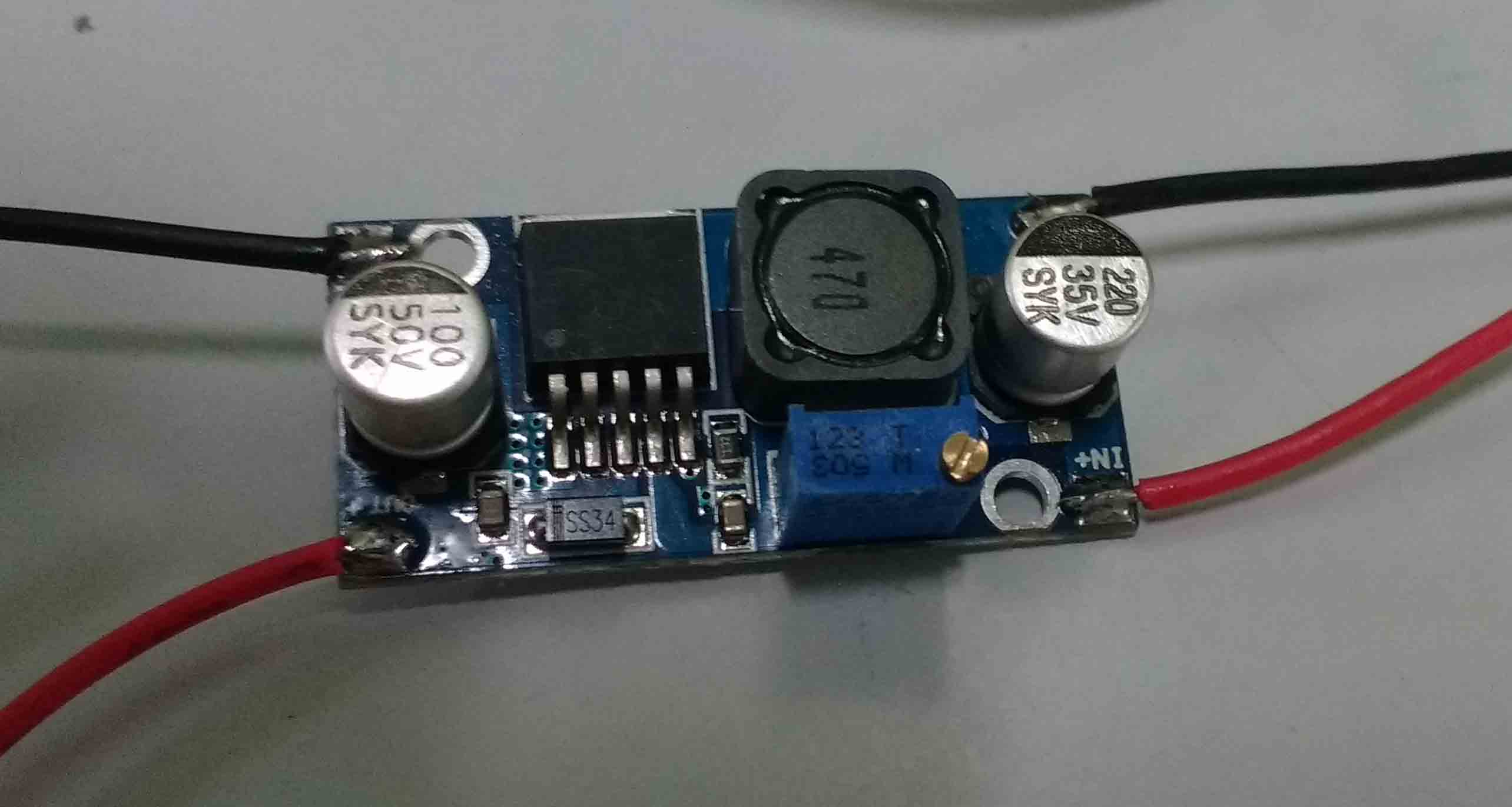
By adjusting the potentio meter on the module we can change the out put voltage of the module. this Youtube video simply explains the working of a boost converter. When I applied 3.6v to the Input I could able to get a maximum readable value of 30.2v from the module .
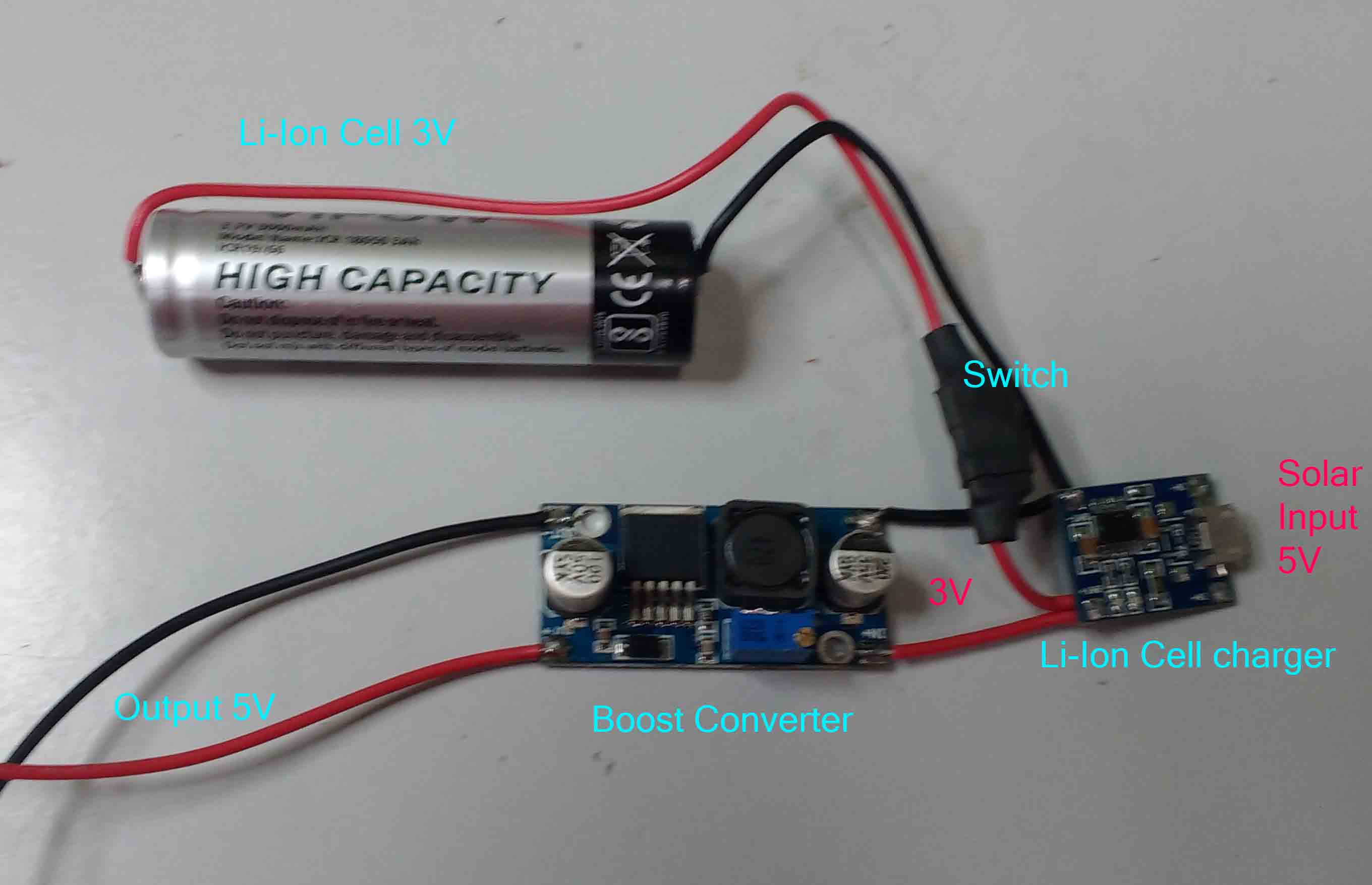
This is the completed Power supply sub system.
 tweezers
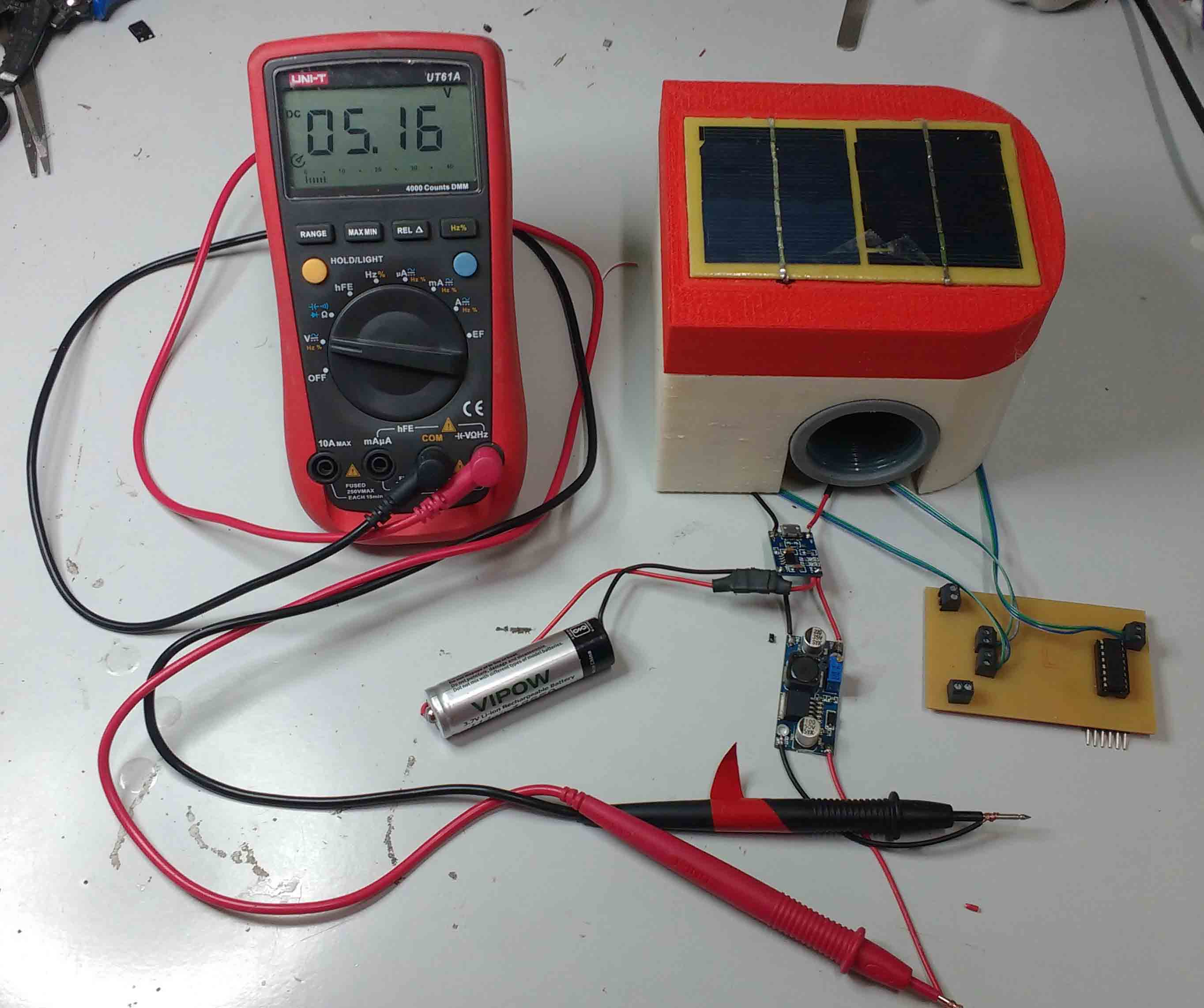
When the solar panel attached to the remaining modules and adjusting the potentio meter .We can see that the terminal voltage now is 5.16V.
I designed a simple Logo for my project in inkscape.I decided to vinyl cut the logo and paste it on my IoT valve project.
This is the png file I have made.

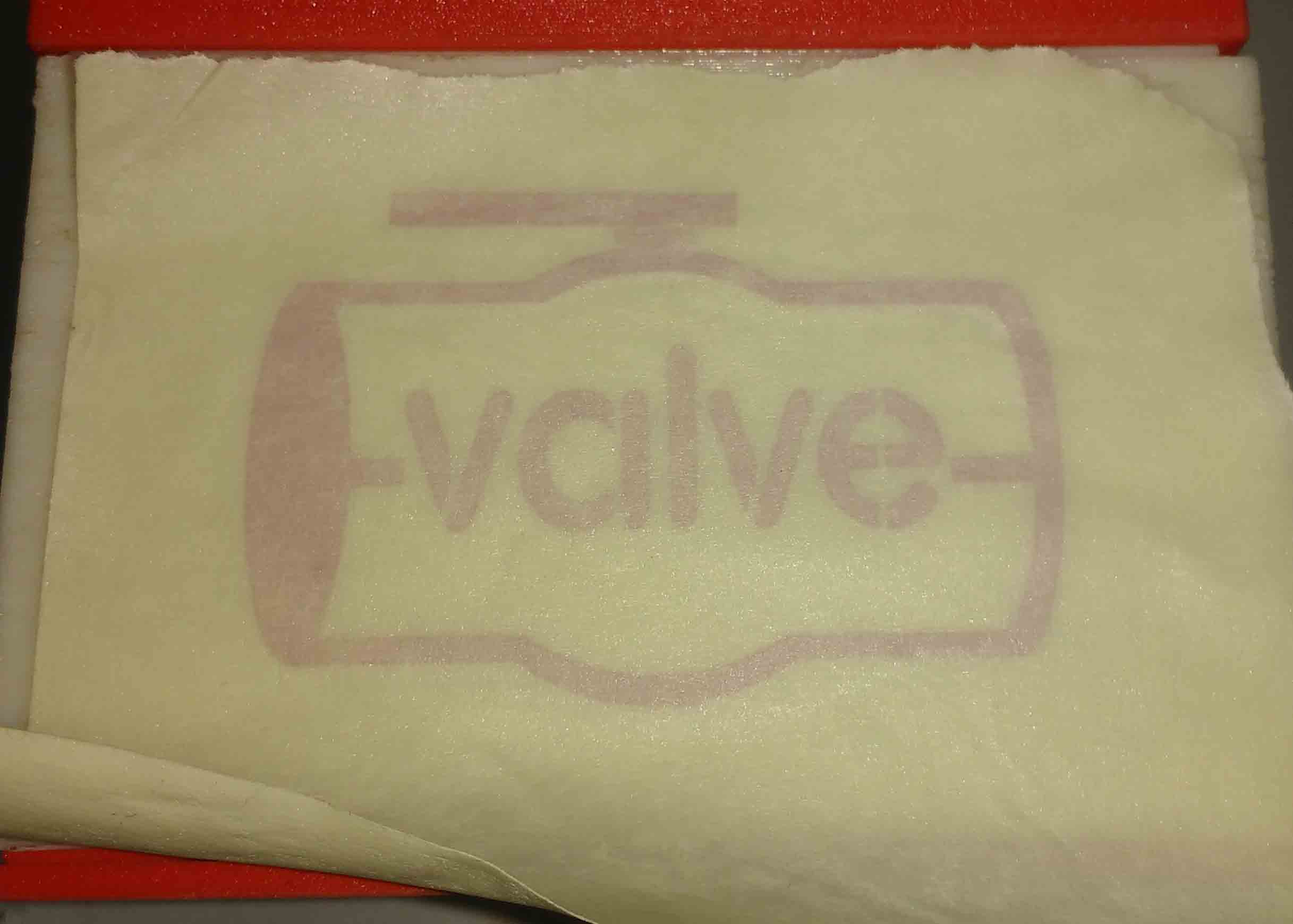
I used the rolland vinyl cutter in our lab to cut my logo.I used force setting as 45 for my cutting. After completing the cutting I carefully removed all unwanted areas from my vinyl sheet using a tweezers.

To transfer the sticker I used a masking tape.
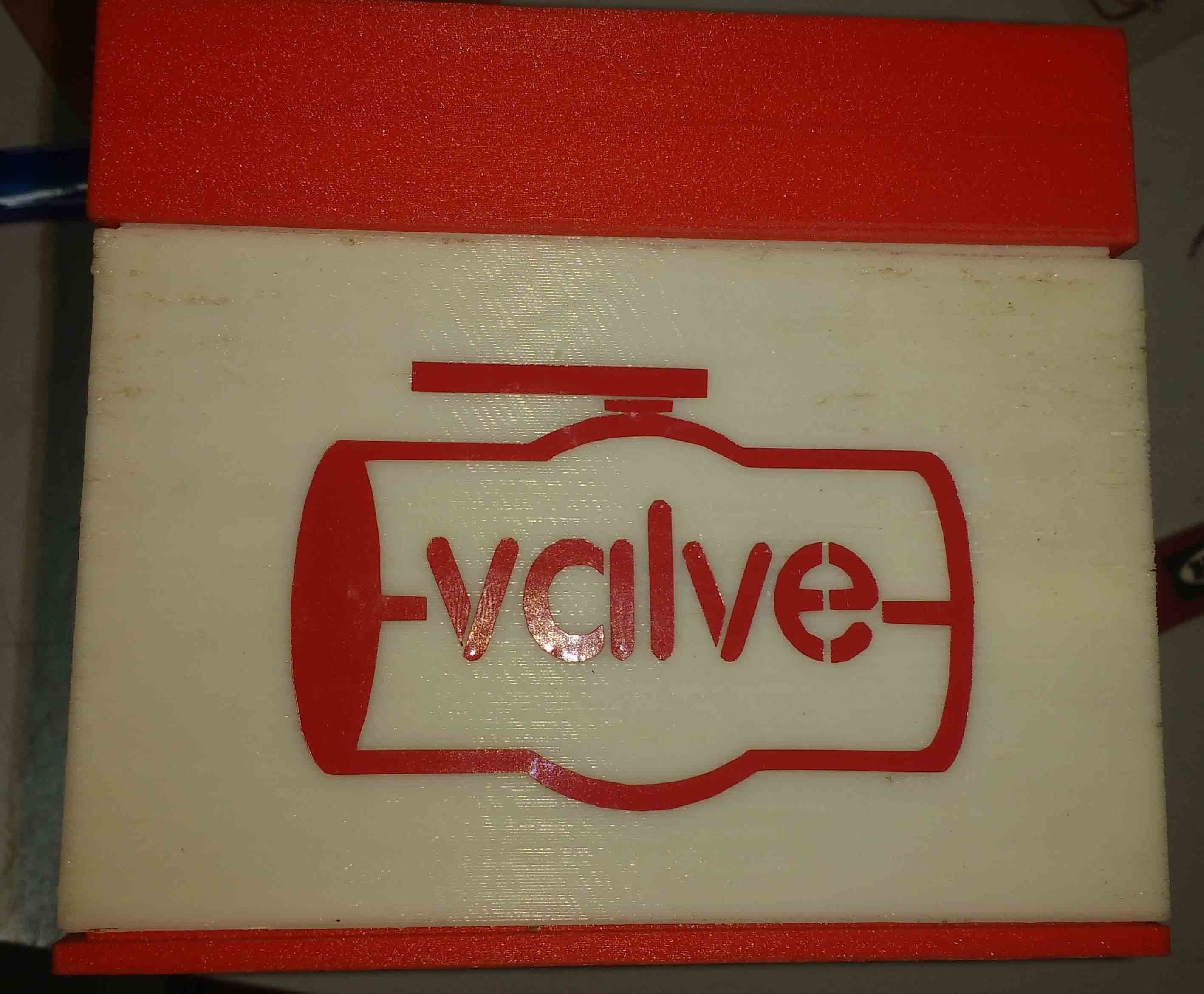
Using the masking tape I carefully placed the sticker on my valve.
This is the photo after removing the masking tape.
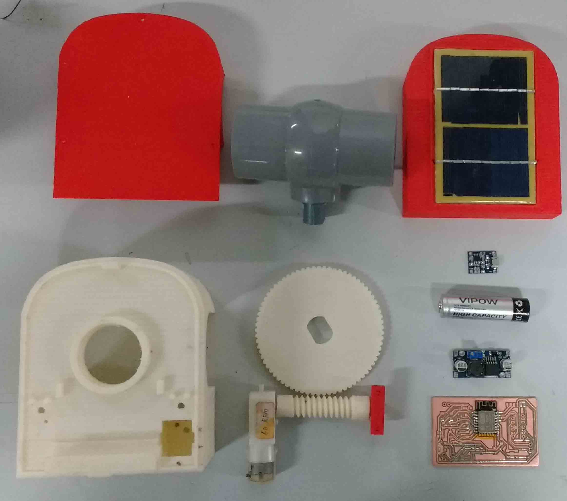
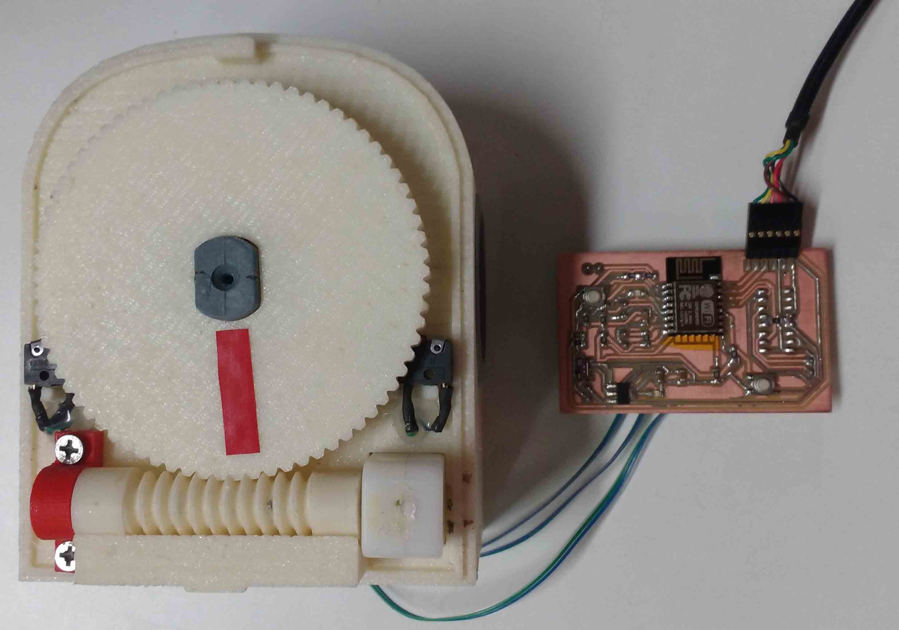
These are the completed functional components Inside my project.
Solder the 2 solar panels in parallel.Now I have 162 mA instead of 81 mA.
Test the mechanism by using test code. And commands Through FTDI cable from a PC .I also used manuel commanding to find my best operation position to place my limit switch end stops.
This is how I planned to assemble my components.
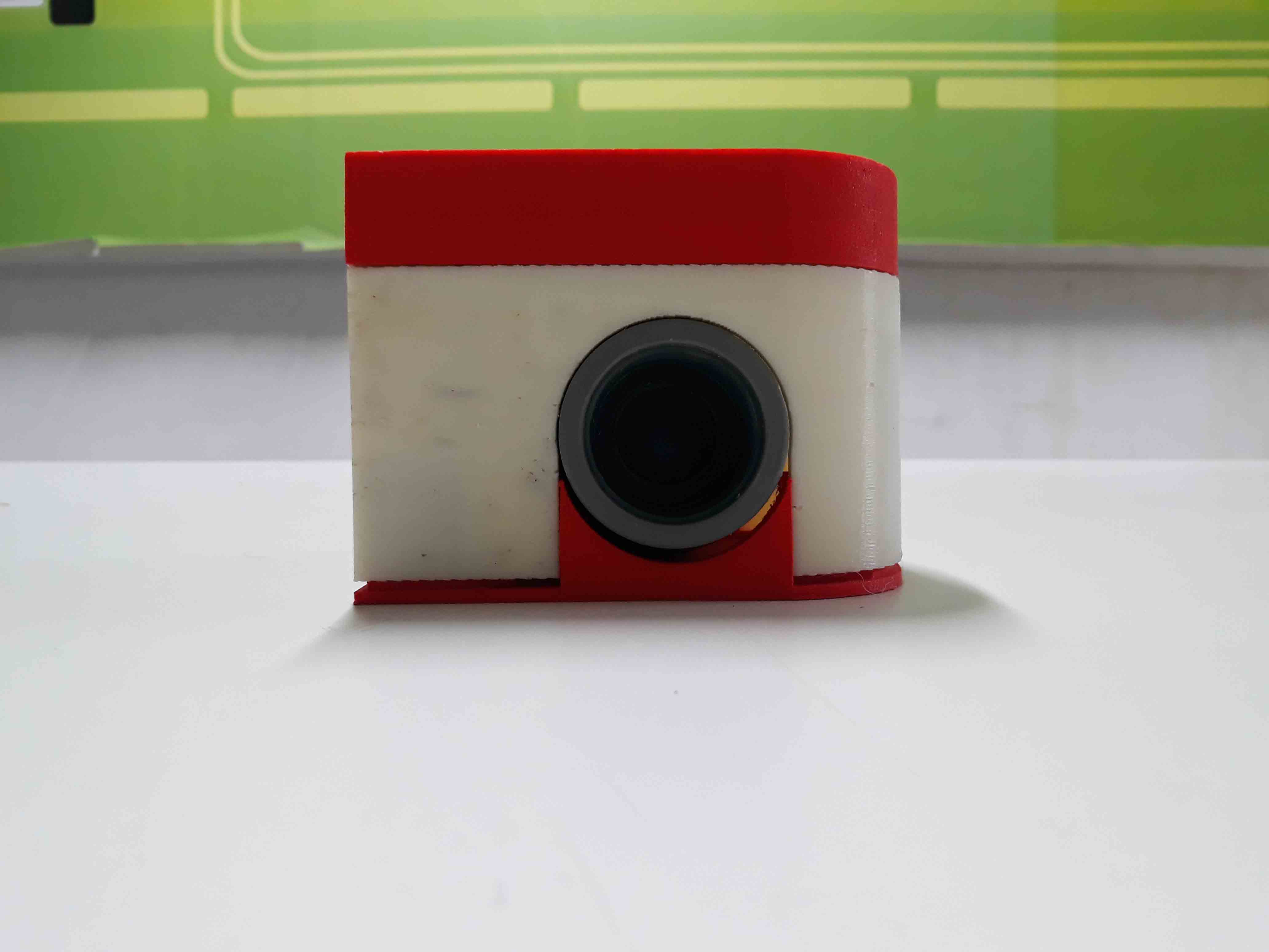
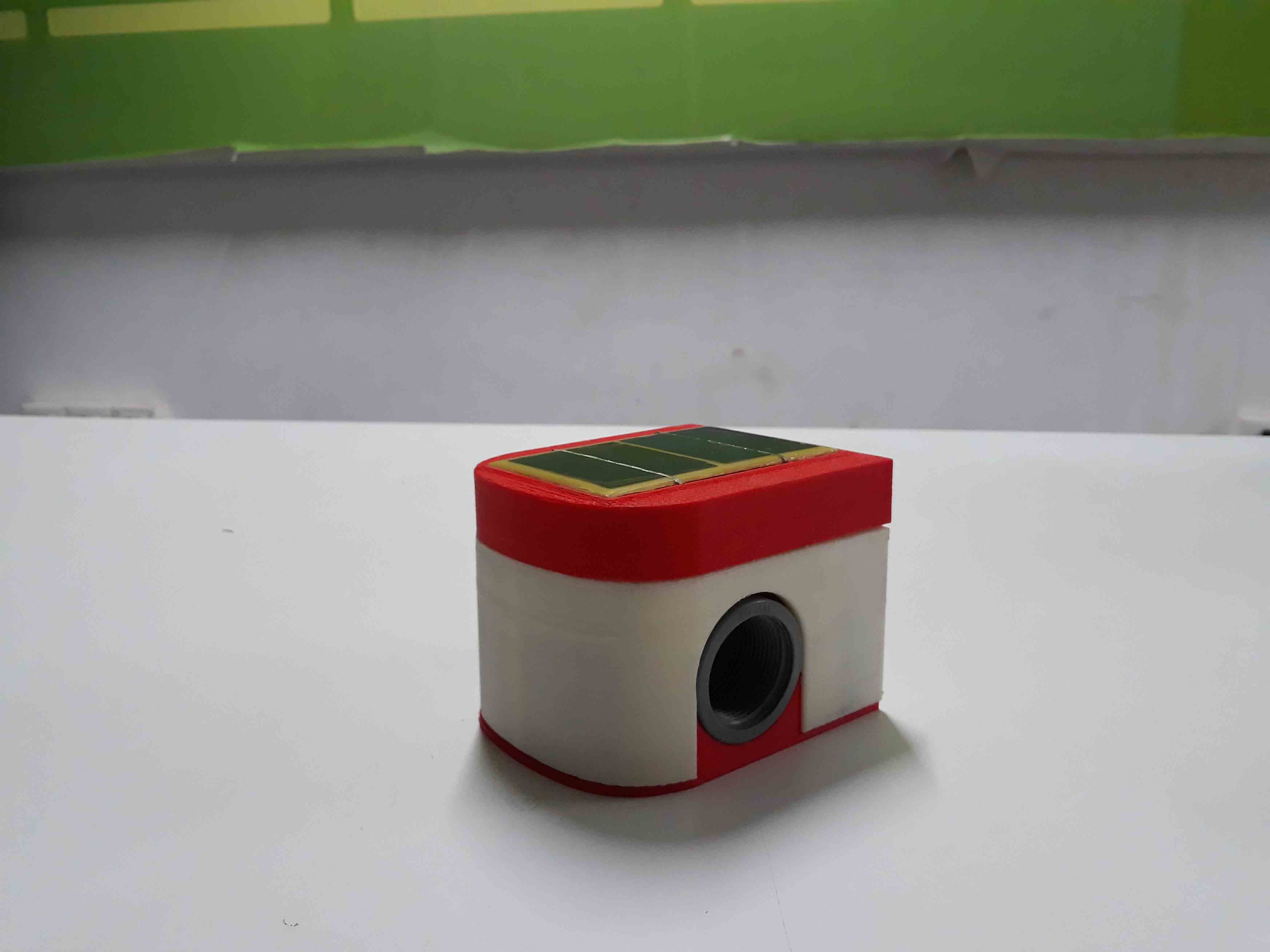
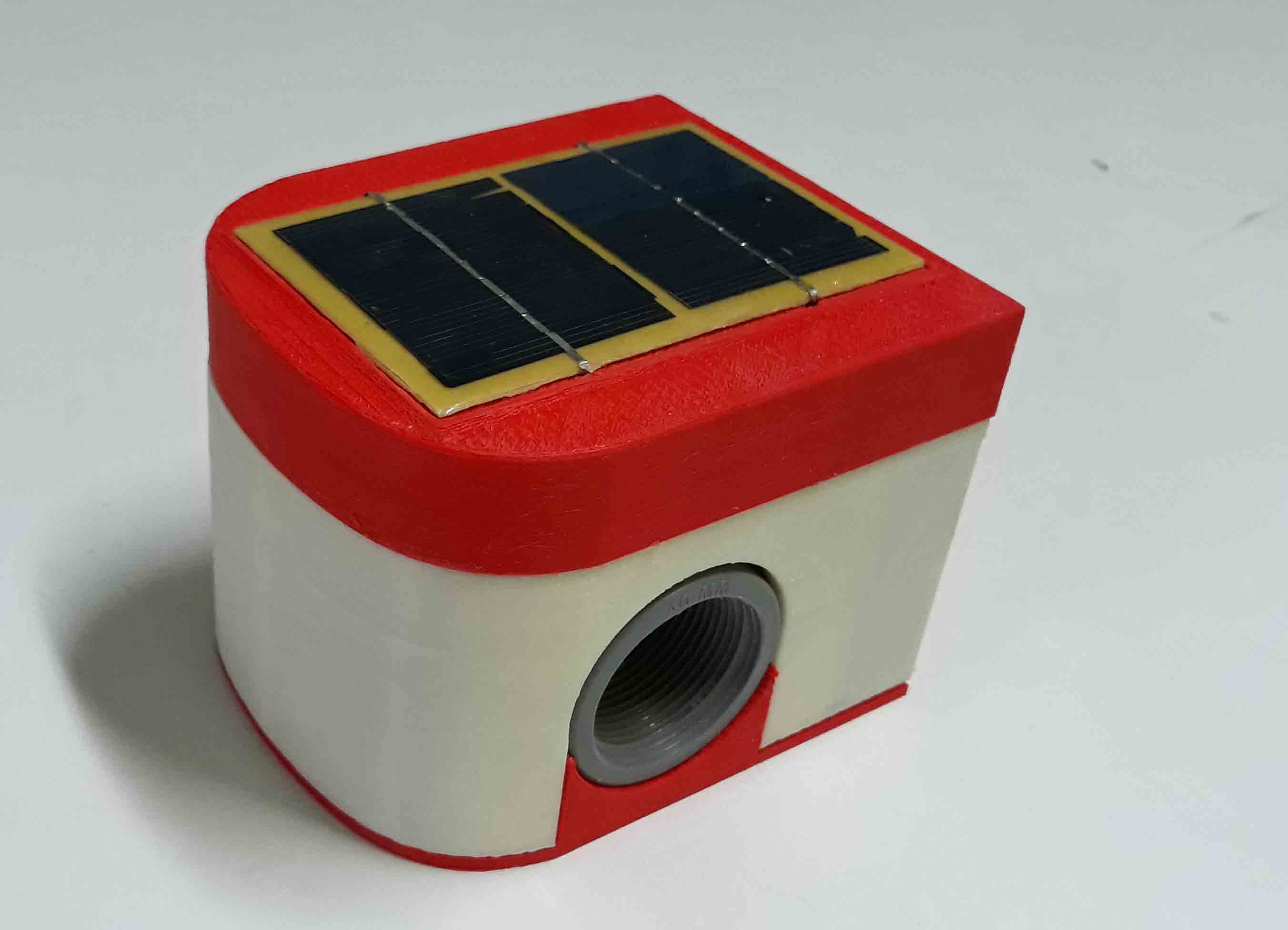
This is my assembled valve.
| Components & Parts | Source | Price (₹) |
|---|---|---|
| esp8266 | Fab Inventory | 0 |
| water valve | Local shop | Rs. 100 |
| limit Switches X 2 | Local shop | Rs. 70 |
| Resistors and capacitors | Fab Inventory | 0 |
| PCB | Fab Inventory | 0 |
| 6mm acryllic | Fab Inventory | 0 |
| Motor driver | Fab Inventory | 0 |
| Bo Motor | Local shop | Rs. 90 |
| Nut and Bolts | Local shops | Rs. 20 |
| Solar Panel | Local shops | Rs. 250 |
| Lithium Ion battary charger module | Local shops | Rs. 50 |
| Boost conerter module | Local shops | Rs. 50 |
| Voltage regulator | Fab Inventory | 0 |
| Vinyl stickers | Fab Inventory | 0 |
| Micro switch | Fab Inventory | 0 |
| Total | ₹ 630 Or $ 9.18 |
For Programming i used Arduino IDE. Before using ESP with Arduino IDE we need to flash it with NodeMCU firmware , download the tool from nodemcu-flasher github repo. if you are using windows open the .exe file and select the Nodemcu binaray (in default it's automatically selected).then click flash
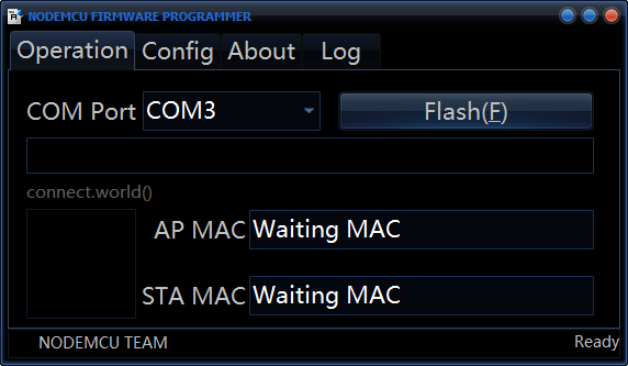
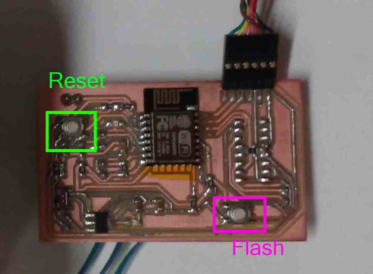
Just click flash and you can burn firmware to ESP8266. Before you doing it,Press the Flash Button.
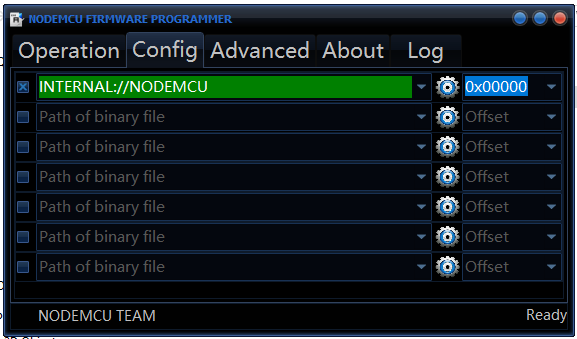
Select NodeMCU Flash Binaray (in default it's automatically selected NodeMCU binary)
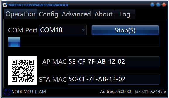
And wait a moment.
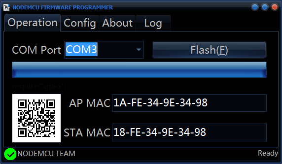
Program success.
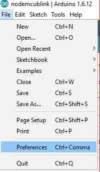
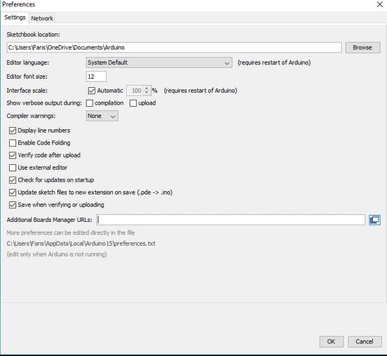
First Install Arduino IDE from Arduino page.
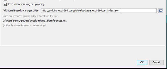
Set additional Board URL for ESP8266/NodeMCU
In Additional Boards Manager, click add and paste the URL there:
http://arduino.esp8266.com/stable/package_esp8266com_index.json And click OK.
Download ESP8266/NodeMCU Board Definitions
Open Board Manager by going to Tools -> Board -> Boards Manger
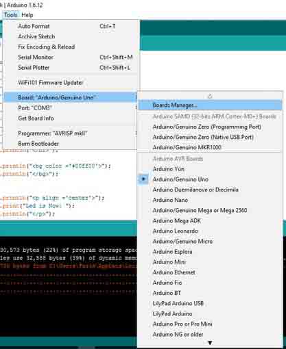
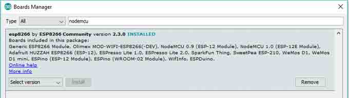
Open Boards Manager and search for NodeMCU and Install It.
This is the arduino code I used for my project
The ESP will create an access point and host a server at port 80
This is an event driven program.If the request consist of "/open" It will call the "handleRooto" and it will call the valve function with "OPEN" as argument.If the request consist of "/close" It will call the "handleRootc" and it will call the valve function with "CLOSE" as argument.
//*********************Wifi AP Settings******************************
#include <ESP8266WiFi.h>
//#include <WiFiClient.h>
#include <ESP8266WebServer.h>

/* Set these to your desired credentials. */
const char *ssid = "FabValve";
const char *password = "";

ESP8266WebServer server(80);

//*********************Valve Parameters*******************************
#define LIMIT_OPEN  13
#define LIMIT_CLOSE  12

#define MOTOR_OPEN  4
#define MOTOR_CLOSE  5

#define BATTERY_LEVEL  A0

#define OPEN  0
#define CLOSE  1

void setup() {
//******************** Valve Setup ***********************************
  Serial.begin(9600);
  pinMode(LIMIT_OPEN, INPUT);
  pinMode(LIMIT_CLOSE, INPUT);
  pinMode(BATTERY_LEVEL, INPUT);
  pinMode(MOTOR_OPEN, OUTPUT);
  pinMode(MOTOR_CLOSE, OUTPUT);
  delay(1000);
  Serial.println();

//********************Access Point Setup******************************

  Serial.print("Configuring access point...");
  WiFi.softAP(ssid, password);

  IPAddress myIP = WiFi.softAPIP();
  Serial.print("AP IP address: ");
  Serial.println(myIP);

//****************** Server Setting **********************************

  server.on("/open", handleRooto);  // call "handleRooto" if request is "/open"
  server.on("/close", handleRootc); // call "handleRootc" if request is "/close"
  server.begin();                   // Start server
  Serial.println("HTTP server started");
}

void loop() {
  server.handleClient();      //HandleClient Request
}

//***************** Handle Opening request ***************************

void handleRooto() {
  server.send(200, "text/plane", "Opening");
  Serial.println("open");
  valve(OPEN);
  server.send(200, "text/plane", "Opened");
}
//*****************Handle Closing Request ****************************

void handleRootc() {
  server.send(200, "text/plane", "Closing");
  Serial.println("close");
  valve(CLOSE);
  server.send(200, "text/plane", "Closed");
}

//****************** Open and Close Valve ****************************

void valve(int dir) {
  if (dir == OPEN) {
    Serial.println("Open");
    while (digitalRead(LIMIT_OPEN) == HIGH) {
      digitalWrite(MOTOR_OPEN, HIGH);
      digitalWrite(MOTOR_CLOSE, LOW);
      Serial.println(digitalRead(LIMIT_OPEN));
      delay(50);
    }
    Serial.println("Stop");
  }
  if (dir == CLOSE) {
    Serial.println("Close");
    while (digitalRead(LIMIT_CLOSE) == HIGH) {
      digitalWrite(MOTOR_OPEN, LOW);
      digitalWrite(MOTOR_CLOSE, HIGH);
      Serial.println(digitalRead(LIMIT_CLOSE));
      delay(50);
    }
    Serial.println("Stop");
  }
  digitalWrite(MOTOR_OPEN, LOW);
  digitalWrite(MOTOR_CLOSE, LOW);
}
I needed an android app which can do the following.
I used MIT app inventor 2 to create my application .Since I needed to have access to my device's WiFi hardware I used a WiFi Manager Extension namedTaifunWiFi for app inventor.
My app consist of 2 screen 1 as the main screen and another screen to edit any information about the valve to be connected. The second page only needed to edit for the first time only .
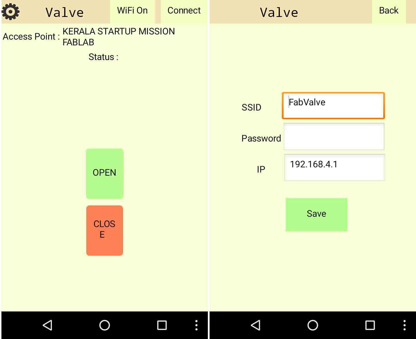
This is the design of my primary screen
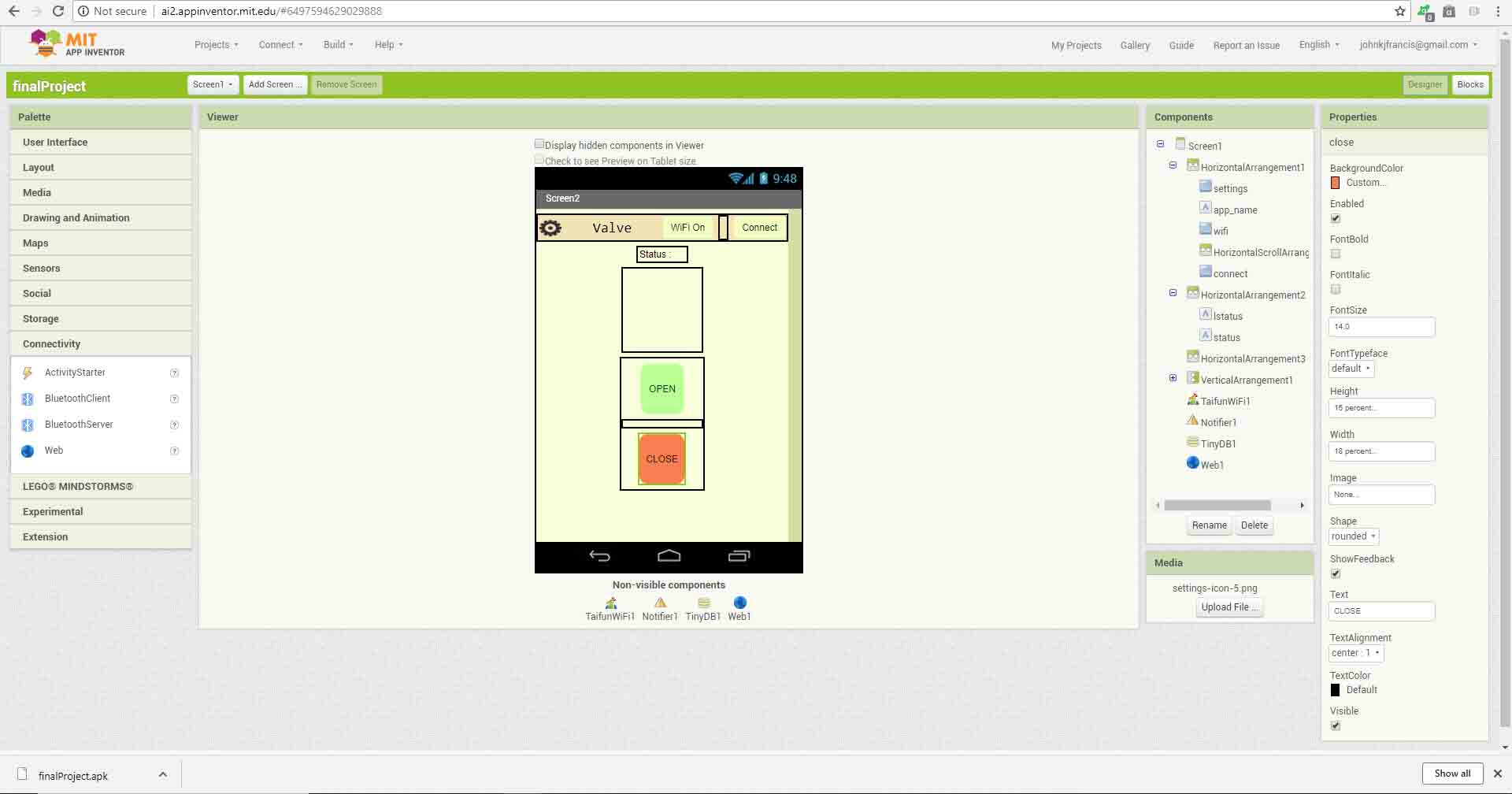
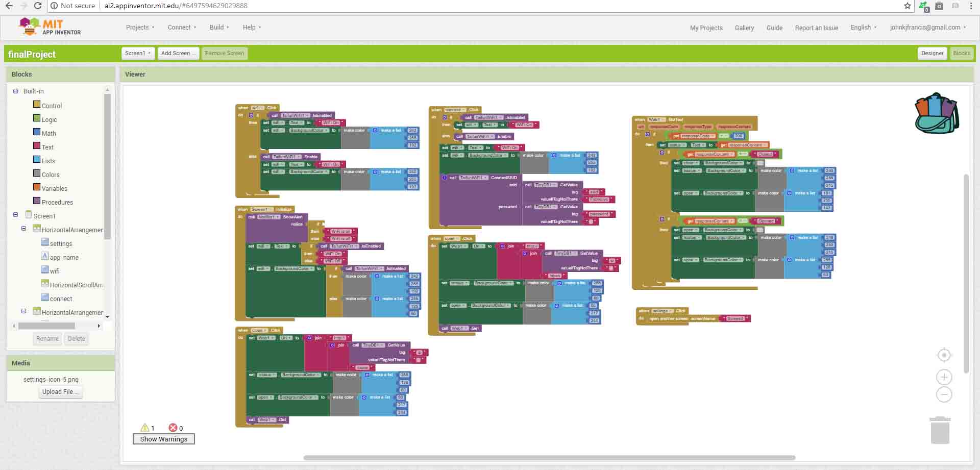
These are the blocks I used in my primary screen
When the screen initialize it check the wifi status and indicate wether it is connected or not
If the Wifi button is pressed It will turn on the wifi .Also If the connect button Is pressed It will turn on the wifi and will connect to the access point generated by the valve.
The page will refresh the name of the access point it connected in every second.
If the open or the close buttons were pressed it will create a html request and will send to the Ip address stored in tiny DB.
when a request may send the app will change the color of the button pressed it will keep that color untle a response code will come from the valve.
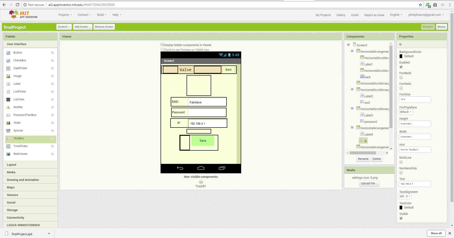
Again the setings button will lead us to the second page.
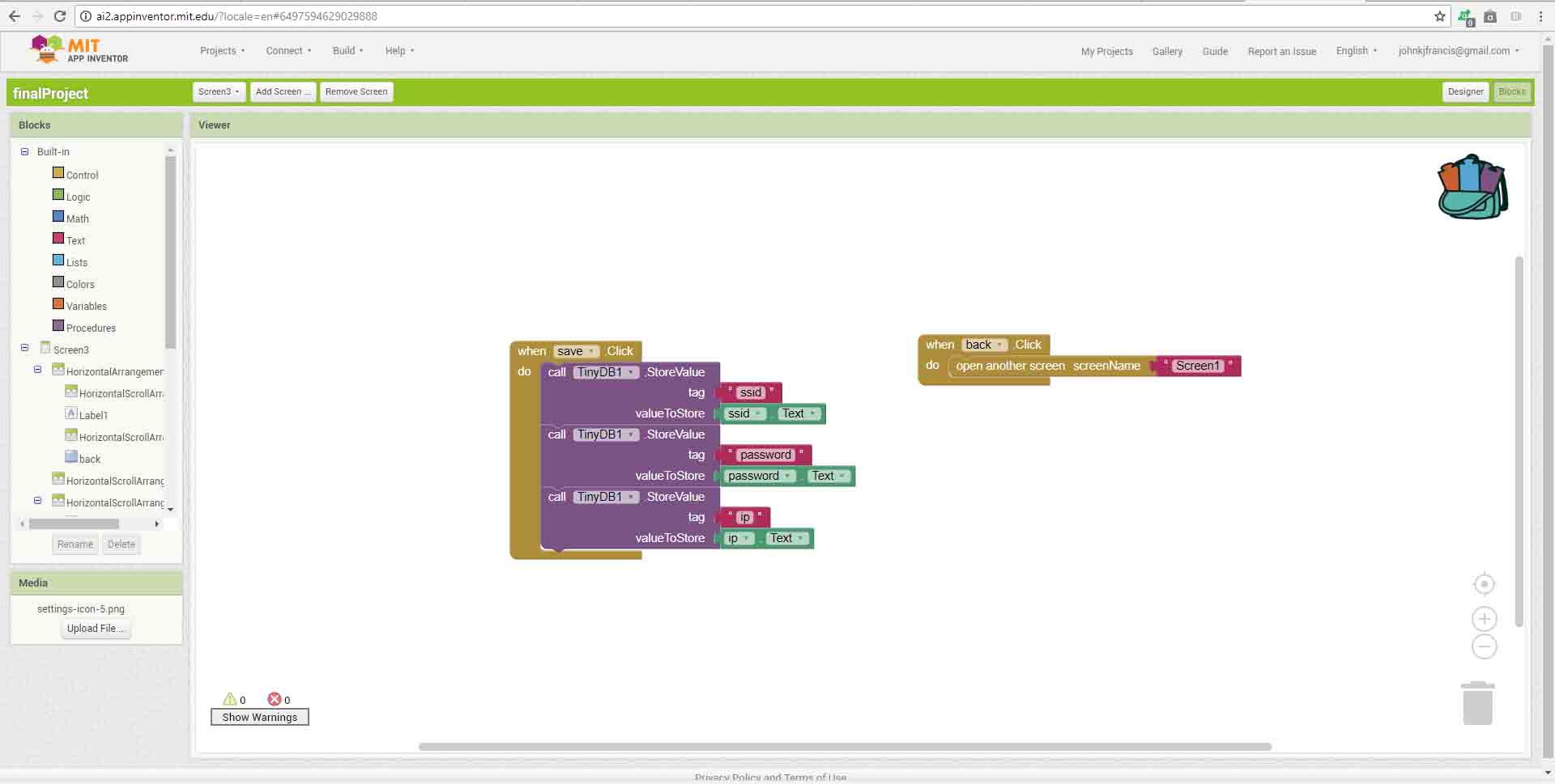
This is the design of my second page . The data we are saving here will be saved to the tiny DB and could be read in the main page and in successive Uses.Here we provides the SSID, password and the Ip address of the device .Since ESP will be in access point mode it will not change without our active intervention.
These are the blocks I have used.
This the Final application In my phone.
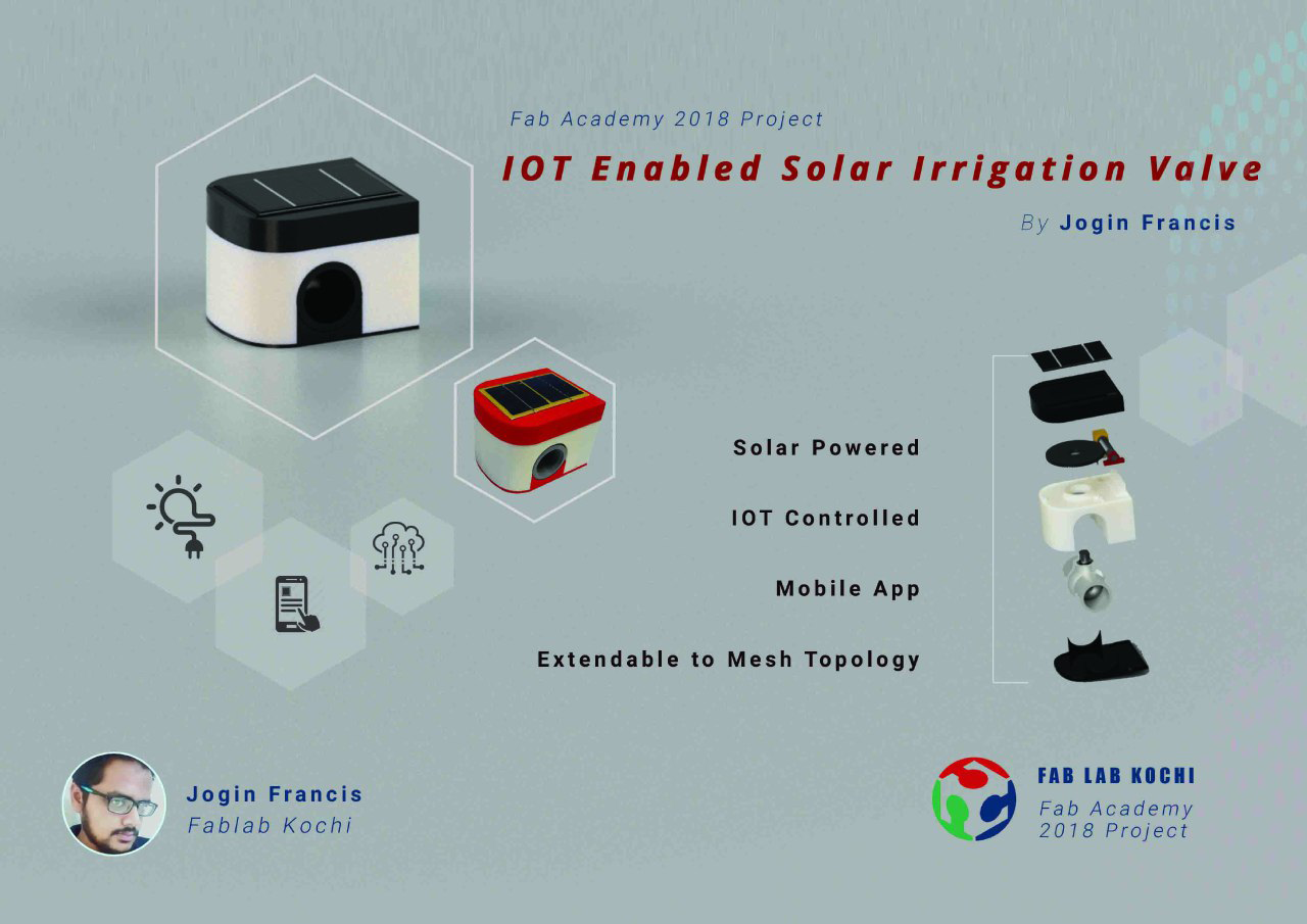
My Final Project Hero Shot
Project Poster
Project Video
My final project is an IoT controlled irrigation valve .The valve could turn on and off the water supply to different parts of an aggricultural land.The system is completely relaying on solar power and also it could be operated using an android app.
I planned to use some of the processes we have learned during our weekly assignments.
This is a small sketch which I have made during my 1st weekly assignment.
This is how I planned to complete my electronics.
I created a "to do" list in trello. and this is how I planned to complete my project.
I used Autodesk Fusion 360 to design my project. To start my project initially I created a library of all commercially available components I needed for my project.Then I added components to the Work and arranged them in a proper way..
I made the enclosure as 3 different parts .A base which support all the mechanical and electronics parts,A bottom cover to hide the bottom portion also protect the battery and electronics from external enviournment factors,A top portion to support the solar panel and also for protecting the motion mechanism.
To design my PCB I had to find out the space I could use for placing my PCB .So 1st I created a model of my available free space.Next i created a rectangular space were I could place my PCB.I created a sketch on the top of the rechangular block and projected my available space geometry to it .then I exported my sketch as a dxf file and imported the same geometry in an eagle document to arrange my pcb.
Finaly I created a supportung Structure for limit switch and some holes for wire management.
Completed CAD design.
I used esp8266 as my processor .The ESP8266 WiFi Module is a self contained SOC with integrated TCP/IP protocol stack that can give any microcontroller access to your WiFi network. The ESP8266 is capable of either hosting an application or offloading all Wi-Fi networking functions from another application processor. Each ESP8266 module comes pre-programmed with an AT command set firmware.
Currently ESP is the most suitable platform for me It provides intergated wifi and onboard microcontroller. So I don't have to add another microcontroller.
For driving my motor I used the L293D dual H bridge motor driver IC.
In addition to the motor driver and soc I added a 3.3v regulator ,2 push button each for reset and flash,A potential divider circuit for cell voltage measurement.I added 3 ports 2 for connecting 2 limit switches and a ftdi port.
This is the completed schematics in eagle.S
I used the dxf file I exported from fusion to create the boundary for my pcb .I arranged everything in the available space and completed my pcb.
Since i needed a strong support structure to support the worm gear and motor mechanism . I decided to Print the base , worm gear and helical gear with dimension sst 1200es 3D printer.Also i planned to use ultimaker for printing the top , bottom covers and the worm gear support.
I also printed the support structure for the worm gear in ultimaker.
Dimension printing my base structure.
Mistake Though I designed with much patients .I had to change the motor which used during my designing. Unfortunately the new one was a little longer than the previous one. So I had to cut the bottom support of my mottor on my base plate.
This is the assembled motion mechanism.
I could have avoided laser cutting .But I couldn't able figureout were to put the limit switch blocks. Because unfortunately my valve doesnot have the same force to rotete at every point. I had to choose the minimum friction quarter to function it properly. So I laser cutted them and assembled them after completing the motion platform so that I could adjuest the limits if the motor can't rotate them at that position.
I made my PCB with Modela MDX20 CNC milling machine I used 1/64 inch V bit for tracing and 1/32 bit for milling and drilling.
For the soldering process 1st I created a list of electronics components I needed .Then place a double side tape next to the table . I arranged all the required components in the tape and started my soldering.
Since I had components on the both sides of the board for easiness I initally soldered the SMD components and then soldered the through hole components .If i were soldered the through hole components 1st I might have faced difficulty to place the board stably on a platform to solder the SMD components.
This is the PCB after fabrication.
The solar panel I decided to use will generate 5V and 81 mA / panel. I decided to use 2 of them so that I will get a total of 162 mA (total 2x81 = 162 mA).Since the solar energy may vary over time. Depending on the availability of sunlight I can't completely relay on solar energy to drive my system. I must have to add some storage mechanism to store excess energy and use them while the valve rotation tooks place.
I need to check wether I could get enough energy from solar to work my device .So I decided to do some calculation.
Initially I decided to took some readings from some online resources to check the feasibility
This is the availibility of solar power in our city kochi. The maximum solar energy receving in a horizontally placed panel of area 1 m2 in a day in june is 3.96 .
The typical efficiency of a small solar panel is arround 12 % (I got it from solarmango.com)
Since I am using a 6.5 cm x 10 cm the amount of energy it could be generated in a day is.
Energy = Area of panel m2 x 3.96 x (12% / 100)
so Energy = (0.065 m x 0.1 m ) x 3.96 x 0.12 = 0.0028782 kWh = 10361.52 Jule
From theory I could have collected 10361.52 Jules in a day.But It will be depending on the efficiency of my charging , boost converter circut and solar panel .Also the charger may stop if the terminal voltage of my solar panel falls below a threshold value.So it may vary in reality.
From testing my board I found that the stand by current I needed for running my valve is arround 110 mA at a voltage of 5V . When I was using the motor to turn on and off the valve the current consumed were raise to 220 mA at 5v.
So the energy I required to work for 24 hr In stand by mode is
energy =IxVxt = .11 x 5 x 60 x 60 x 24 = 47520 J
The energy I required to turn off or on the valve is(it took 30 seconds to turn on or off )
energy = IxVxt = .22 x 5 x 30 = 33 Jule
Next I have to physically test my pannels.
I found that during the peek hours I gets 5.08v at 162 mA(from 2 panels) from my solar panels.
The figure below shows the avalibility of solar energy in a day . Fom that we can say that the total solar energy could be converted can be written as = peek sun hours x peek output.
Typical peek sun hours in kerala is 5 hours . So possible energy/day = (.162 x 5) x (60 x 60 x 5) = 14580 Jule (We have got 10361.52 Jule during calculation from online data so this is an acceptable data.)
If I need 33 jules for turning on and off my valve.So I could have done (14580 / 33) 441 turn on and off / day with the available sun light .
Problem But currently I am using my board in access point mode so I can't use power saving mode for now . The board consumes an enormous 47.52 KJ/day .If I am going to use ESP in this way I might need a solar panel of 3x of my current area .So for my future developmets I decided to use Bluetooth low energy .But to complete my fab project I am using ESP for now .
The solar panel producess 5 V but the terminal voltage of my Li-ion cell is 3.7v So to charge my cell by maintaining the charging current I need to have a battery charging circuit . Normaly Li-ion cells have a very low internal resistance so if we apply a higher voltage a large current may flow and the I2Rt heat loss may damage our cell .So usually we needs a charging circuit for controll the current . But since my solar panel only produces a maximum current of 162 mA I thought It won't be a problem for me . But when I searched the web there were a lot of people using a charging circut .Don't know why but due to that I also decided to use the charging circuit.
Earlier I was planning to create a charging circut of my one using the SoC itself.The soc will read the current using a series resistor and controll the current with a mosfet . But later I found thet time is limted and also ESP only have a single analog pin which I had to use for reading the Battery Charge status.So I forced to buy two module one for the battery management and another for boost comverting(3.7v to 5v) .I needed a boost converter to produce a 5V for my motor and L293d motor driver.
I used tp4056 module for cell charging(5v to 3.7v) and LM2596 DC-DC Buck Converter for bosting the voltage form Li-ion cell's 3.7 volt to 5v.The image shown below is the LM2596 DC-DC Buck Converter module
By adjusting the potentio meter on the module we can change the out put voltage of the module. this Youtube video simply explains the working of a boost converter. When I applied 3.6v to the Input I could able to get a maximum readable value of 30.2v from the module .
This is the completed Power supply sub system.
tweezers
When the solar panel attached to the remaining modules and adjusting the potentio meter .We can see that the terminal voltage now is 5.16V.
I designed a simple Logo for my project in inkscape.I decided to vinyl cut the logo and paste it on my IoT valve project.
This is the png file I have made.
I used the rolland vinyl cutter in our lab to cut my logo.I used force setting as 45 for my cutting. After completing the cutting I carefully removed all unwanted areas from my vinyl sheet using a tweezers.
To transfer the sticker I used a masking tape.
Using the masking tape I carefully placed the sticker on my valve.
This is the photo after removing the masking tape.
These are the completed functional components Inside my project.
Solder the 2 solar panels in parallel.Now I have 162 mA instead of 81 mA.
Test the mechanism by using test code. And commands Through FTDI cable from a PC .I also used manuel commanding to find my best operation position to place my limit switch end stops.
This is how I planned to assemble my components.
This is my assembled valve.
| Components & Parts | Source | Price (₹) |
|---|---|---|
| esp8266 | Fab Inventory | 0 |
| water valve | Local shop | Rs. 100 |
| limit Switches X 2 | Local shop | Rs. 70 |
| Resistors and capacitors | Fab Inventory | 0 |
| PCB | Fab Inventory | 0 |
| 6mm acryllic | Fab Inventory | 0 |
| Motor driver | Fab Inventory | 0 |
| Bo Motor | Local shop | Rs. 90 |
| Nut and Bolts | Local shops | Rs. 20 |
| Solar Panel | Local shops | Rs. 250 |
| Lithium Ion battary charger module | Local shops | Rs. 50 |
| Boost conerter module | Local shops | Rs. 50 |
| Voltage regulator | Fab Inventory | 0 |
| Vinyl stickers | Fab Inventory | 0 |
| Micro switch | Fab Inventory | 0 |
| Total | ₹ 630 Or $ 9.18 |
For Programming i used Arduino IDE. Before using ESP with Arduino IDE we need to flash it with NodeMCU firmware , download the tool from nodemcu-flasher github repo. if you are using windows open the .exe file and select the Nodemcu binaray (in default it's automatically selected).then click flash
Just click flash and you can burn firmware to ESP8266. Before you doing it,Press the Flash Button.
Select NodeMCU Flash Binaray (in default it's automatically selected NodeMCU binary)
And wait a moment.
Program success.
First Install Arduino IDE from Arduino page.
Set additional Board URL for ESP8266/NodeMCU
In Additional Boards Manager, click add and paste the URL there:
http://arduino.esp8266.com/stable/package_esp8266com_index.json And click OK.
Download ESP8266/NodeMCU Board Definitions
Open Board Manager by going to Tools -> Board -> Boards Manger
Open Boards Manager and search for NodeMCU and Install It.
This is the arduino code I used for my project
The ESP will create an access point and host a server at port 80
This is an event driven program.If the request consist of "/open" It will call the "handleRooto" and it will call the valve function with "OPEN" as argument.If the request consist of "/close" It will call the "handleRootc" and it will call the valve function with "CLOSE" as argument.
//*********************Wifi AP Settings******************************
#include <ESP8266WiFi.h>
//#include <WiFiClient.h>
#include <ESP8266WebServer.h>

/* Set these to your desired credentials. */
const char *ssid = "FabValve";
const char *password = "";

ESP8266WebServer server(80);

//*********************Valve Parameters*******************************
#define LIMIT_OPEN  13
#define LIMIT_CLOSE  12

#define MOTOR_OPEN  4
#define MOTOR_CLOSE  5

#define BATTERY_LEVEL  A0

#define OPEN  0
#define CLOSE  1

void setup() {
//******************** Valve Setup ***********************************
  Serial.begin(9600);
  pinMode(LIMIT_OPEN, INPUT);
  pinMode(LIMIT_CLOSE, INPUT);
  pinMode(BATTERY_LEVEL, INPUT);
  pinMode(MOTOR_OPEN, OUTPUT);
  pinMode(MOTOR_CLOSE, OUTPUT);
  delay(1000);
  Serial.println();

//********************Access Point Setup******************************

  Serial.print("Configuring access point...");
  WiFi.softAP(ssid, password);

  IPAddress myIP = WiFi.softAPIP();
  Serial.print("AP IP address: ");
  Serial.println(myIP);

//****************** Server Setting **********************************

  server.on("/open", handleRooto);  // call "handleRooto" if request is "/open"
  server.on("/close", handleRootc); // call "handleRootc" if request is "/close"
  server.begin();                   // Start server
  Serial.println("HTTP server started");
}

void loop() {
  server.handleClient();      //HandleClient Request
}

//***************** Handle Opening request ***************************

void handleRooto() {
  server.send(200, "text/plane", "Opening");
  Serial.println("open");
  valve(OPEN);
  server.send(200, "text/plane", "Opened");
}
//*****************Handle Closing Request ****************************

void handleRootc() {
  server.send(200, "text/plane", "Closing");
  Serial.println("close");
  valve(CLOSE);
  server.send(200, "text/plane", "Closed");
}

//****************** Open and Close Valve ****************************

void valve(int dir) {
  if (dir == OPEN) {
    Serial.println("Open");
    while (digitalRead(LIMIT_OPEN) == HIGH) {
      digitalWrite(MOTOR_OPEN, HIGH);
      digitalWrite(MOTOR_CLOSE, LOW);
      Serial.println(digitalRead(LIMIT_OPEN));
      delay(50);
    }
    Serial.println("Stop");
  }
  if (dir == CLOSE) {
    Serial.println("Close");
    while (digitalRead(LIMIT_CLOSE) == HIGH) {
      digitalWrite(MOTOR_OPEN, LOW);
      digitalWrite(MOTOR_CLOSE, HIGH);
      Serial.println(digitalRead(LIMIT_CLOSE));
      delay(50);
    }
    Serial.println("Stop");
  }
  digitalWrite(MOTOR_OPEN, LOW);
  digitalWrite(MOTOR_CLOSE, LOW);
}
I needed an android app which can do the following.
I used MIT app inventor 2 to create my application .Since I needed to have access to my device's WiFi hardware I used a WiFi Manager Extension namedTaifunWiFi for app inventor.
My app consist of 2 screen 1 as the main screen and another screen to edit any information about the valve to be connected. The second page only needed to edit for the first time only .
This is the design of my primary screen
These are the blocks I used in my primary screen
When the screen initialize it check the wifi status and indicate wether it is connected or not
If the Wifi button is pressed It will turn on the wifi .Also If the connect button Is pressed It will turn on the wifi and will connect to the access point generated by the valve.
The page will refresh the name of the access point it connected in every second.
If the open or the close buttons were pressed it will create a html request and will send to the Ip address stored in tiny DB.
when a request may send the app will change the color of the button pressed it will keep that color untle a response code will come from the valve.
Again the setings button will lead us to the second page.
This is the design of my second page . The data we are saving here will be saved to the tiny DB and could be read in the main page and in successive Uses.Here we provides the SSID, password and the Ip address of the device .Since ESP will be in access point mode it will not change without our active intervention.
These are the blocks I have used.
This the Final application In my phone.
My Final Project Hero Shot
Project Poster
Project Video