Assignment :
Group Assignment : measure the power consumption of an output device
Individual Assignment : add an output device to a microcontroller board you've designed, and program it to do something
Machines are just like us .They need sensory inputs like our eyes and ears and processors like our brain and also need output devices to show the result . In this week I am going to try some output devices .In the perevious weeks I used Attiny 44 .So i decided to choose this opertunity to try another microcontroller also .Attiny is a very good and cheep microcontroller but when i need to control more devices the number of available pins became an issue . So this week i am usin the Atmega328p microcontroller
The high-performance Microchip picoPower 8-bit AVR RISC-based microcontroller combines 32KB ISP flash memory with read-while-write capabilities, 1024B EEPROM, 2KB SRAM, 23 general purpose I/O lines, 32 general purpose working registers, three flexible timer/counters with compare modes, internal and external interrupts, serial programmable USART, a byte-oriented 2-wire serial interface, SPI serial port, a 6-channel 10-bit A/D converter (8-channels in TQFP and QFN/MLF packages), programmable watchdog timer with internal oscillator, and five software selectable power saving modes. The device operates between 1.8-5.5 volts. By executing powerful instructions in a single clock cycle, the device achieves throughputs approaching 1 MIPS per MHz, balancing power consumption and processing speed.
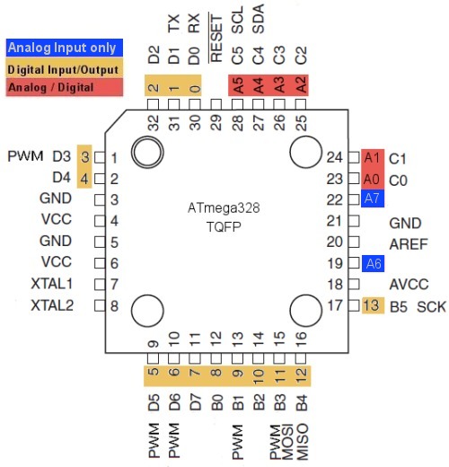
We can learn more about the chip here Atmega328p.
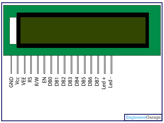
LCD (Liquid Crystal Display) screen is an electronic display module and find a wide range of applications. A 16x2 LCD display is very basic module and is very commonly used in various devices and circuits. These modules are preferred over seven segments and other multi segment LEDs. The reasons being: LCDs are economical; easily programmable; have no limitation of displaying special & even custom characters (unlike in seven segments), animations and so on.
A 16x2 LCD means it can display 16 characters per line and there are 2 such lines. In this LCD each character is displayed in 5x7 pixel matrix. This LCD has two registers, namely, Command and Data.
The command register stores the command instructions given to the LCD. A command is an instruction given to LCD to do a predefined task like initializing it, clearing its screen, setting the cursor position, controlling display etc. The data register stores the data to be displayed on the LCD. The data is the ASCII value of the character to be displayed on the LCD. Click to learn more about internal structure of a LCD.
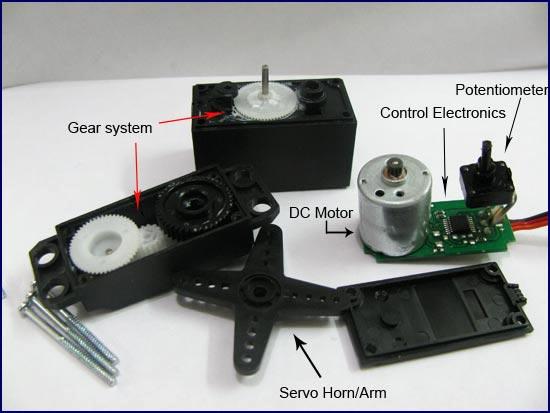
A DC servo motor is an assembly of four major components, namely a DC motor, a position sensing device, a gear assembly, and a control circuit. The above figure shows the parts that consisting in RC servo motors in which small DC motor is employed for driving the loads at precise speed and position..
A DC reference voltage is set to the value corresponding to the desired output. This voltage can be applied by using another potentiometer, control pulse width to voltage converter, or through timers depending on the control circuitry.
The dial on the potentiometer produces a corresponding voltage which is then applied as one of the inputs to error amplifier. In some circuits, a control pulse is used to produce DC reference voltage corresponding to desired position or speed of the motor and it is applied to a pulse width to voltage converter. In this converter, the capacitor starts charging at a constant rate when the pulse high. Then the charge on the capacitor is fed to the buffer amplifier when the pulse is low and this charge is further applied to the error amplifier. Click to learn more about Servos.
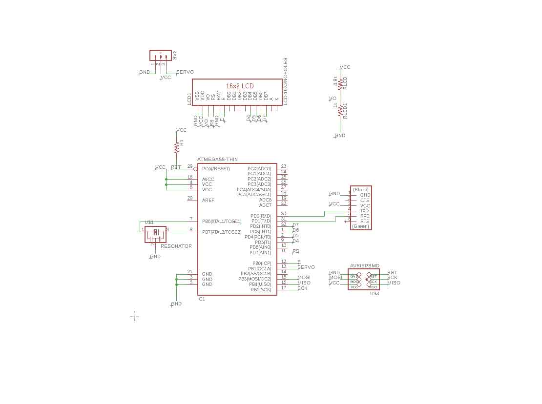
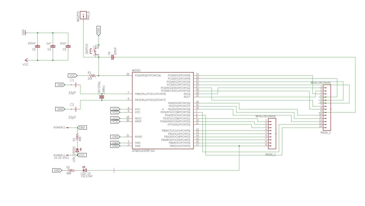
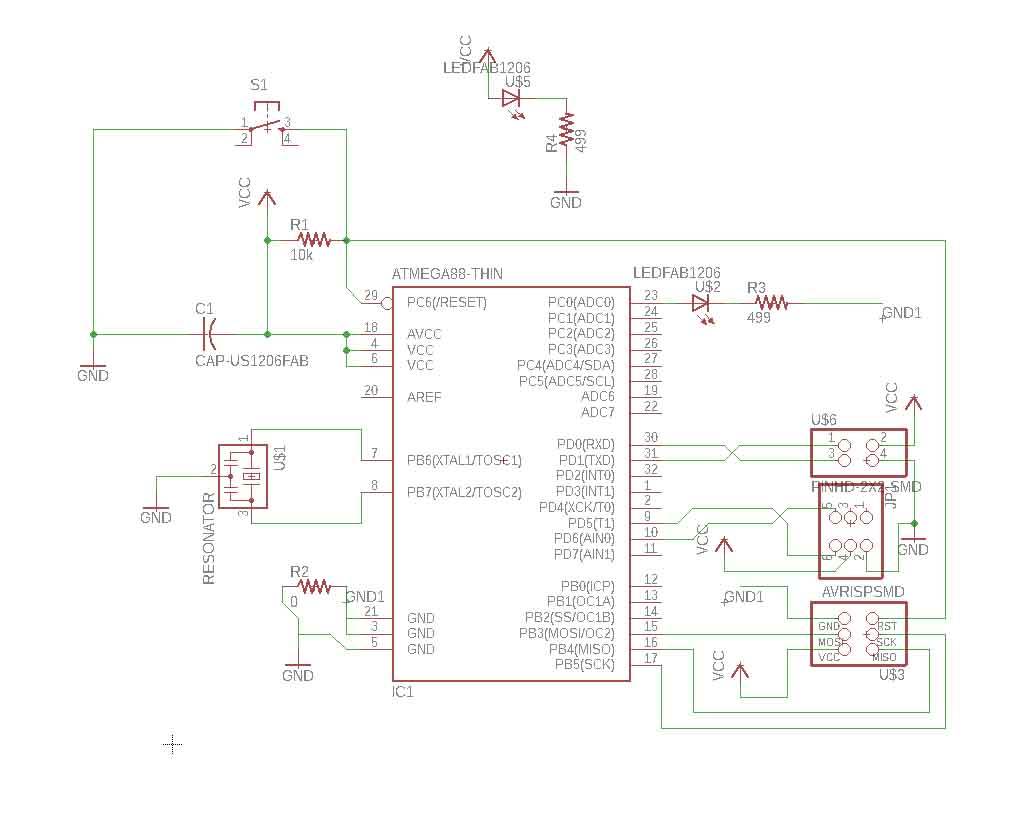
For the output week I decided to make a PCB to interface an LCD display and a servo motor with Atmega 328p microcontroller .
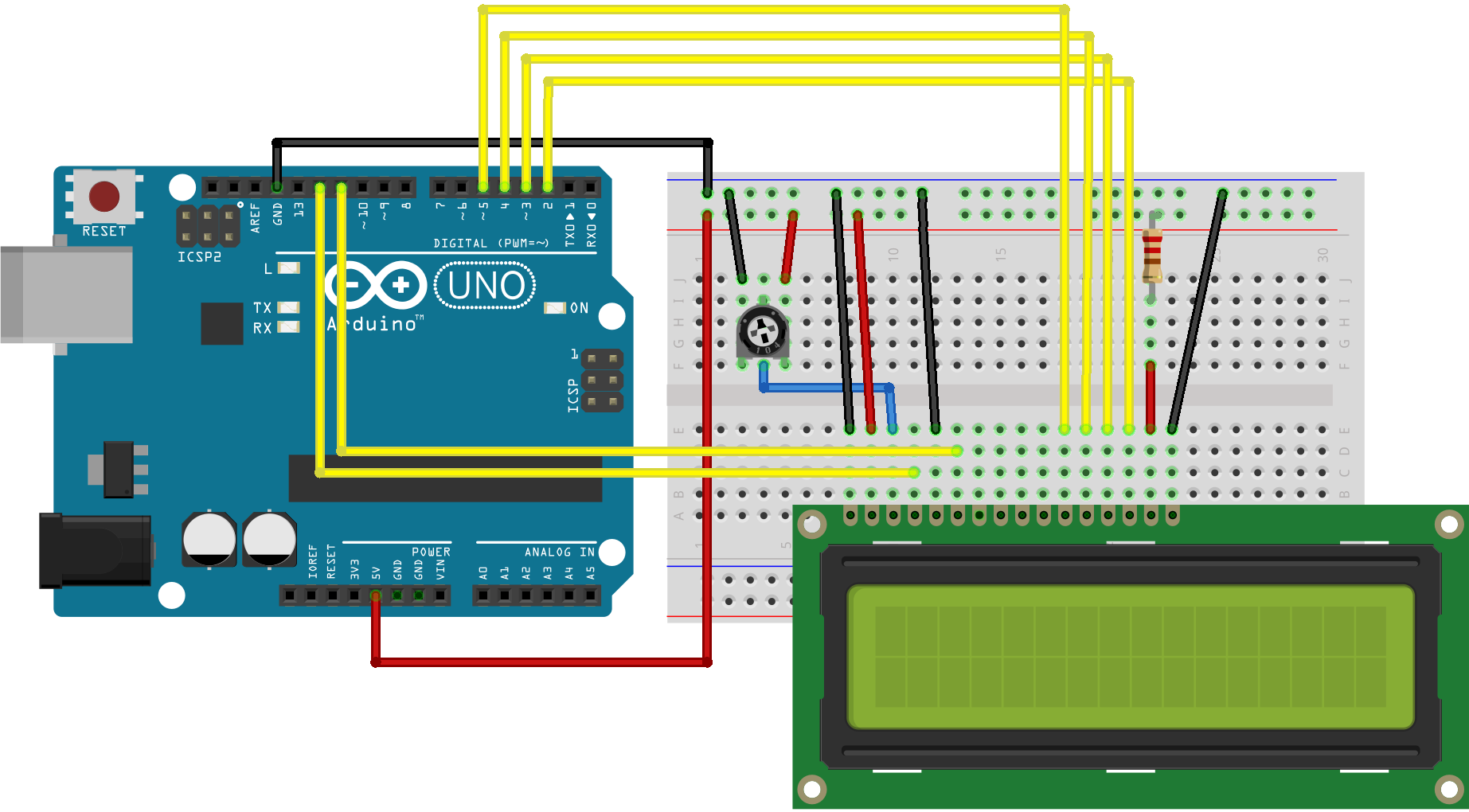
I tried the above connection with an arduino and ensured the LCD is working properly.
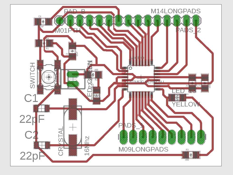
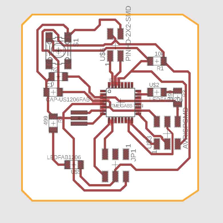
Initially I decised to design the PCB with Atmega 328p and 20 MHz resonator insted of christal and capacitor arrangement.
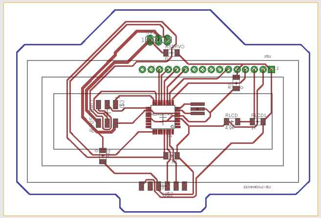
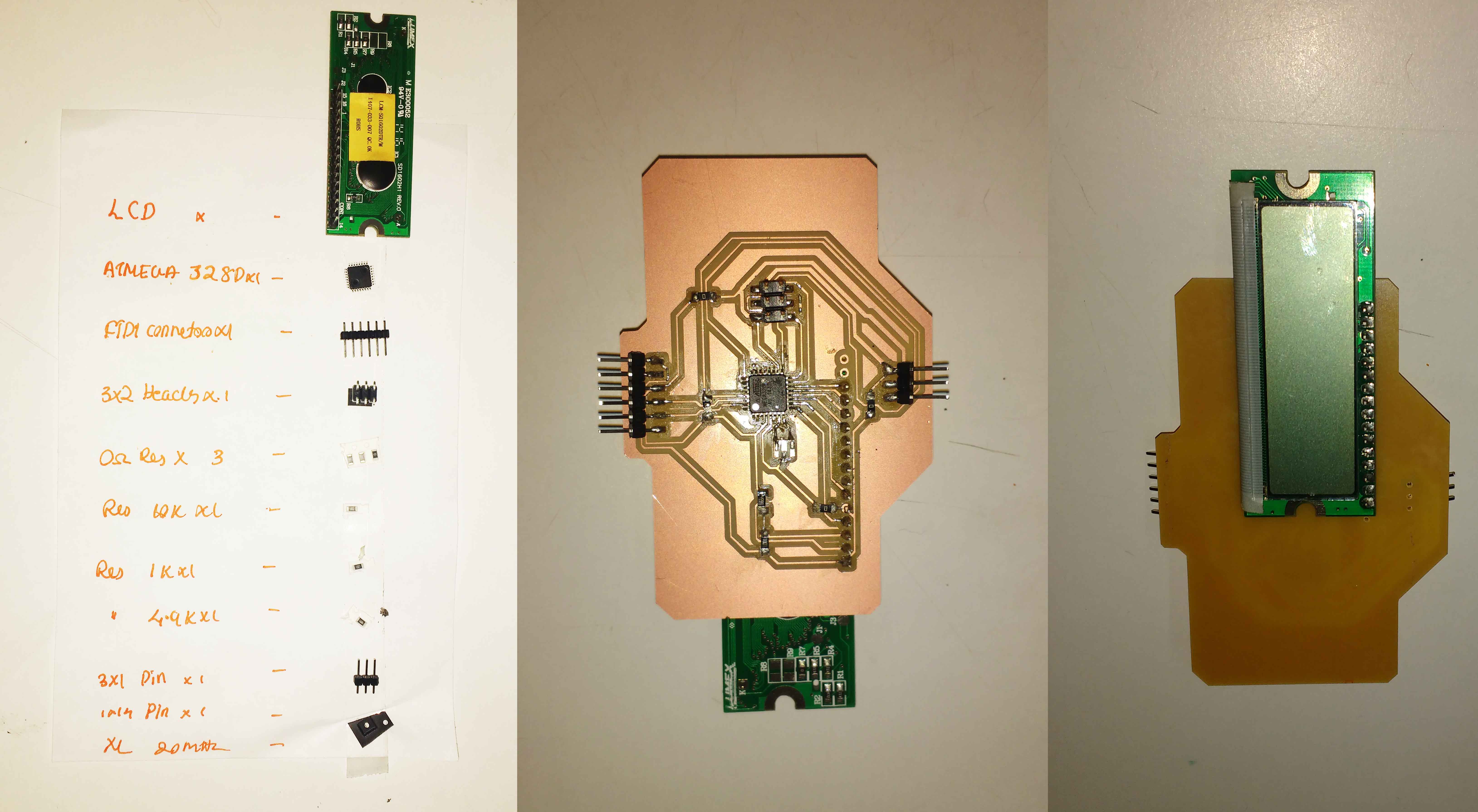
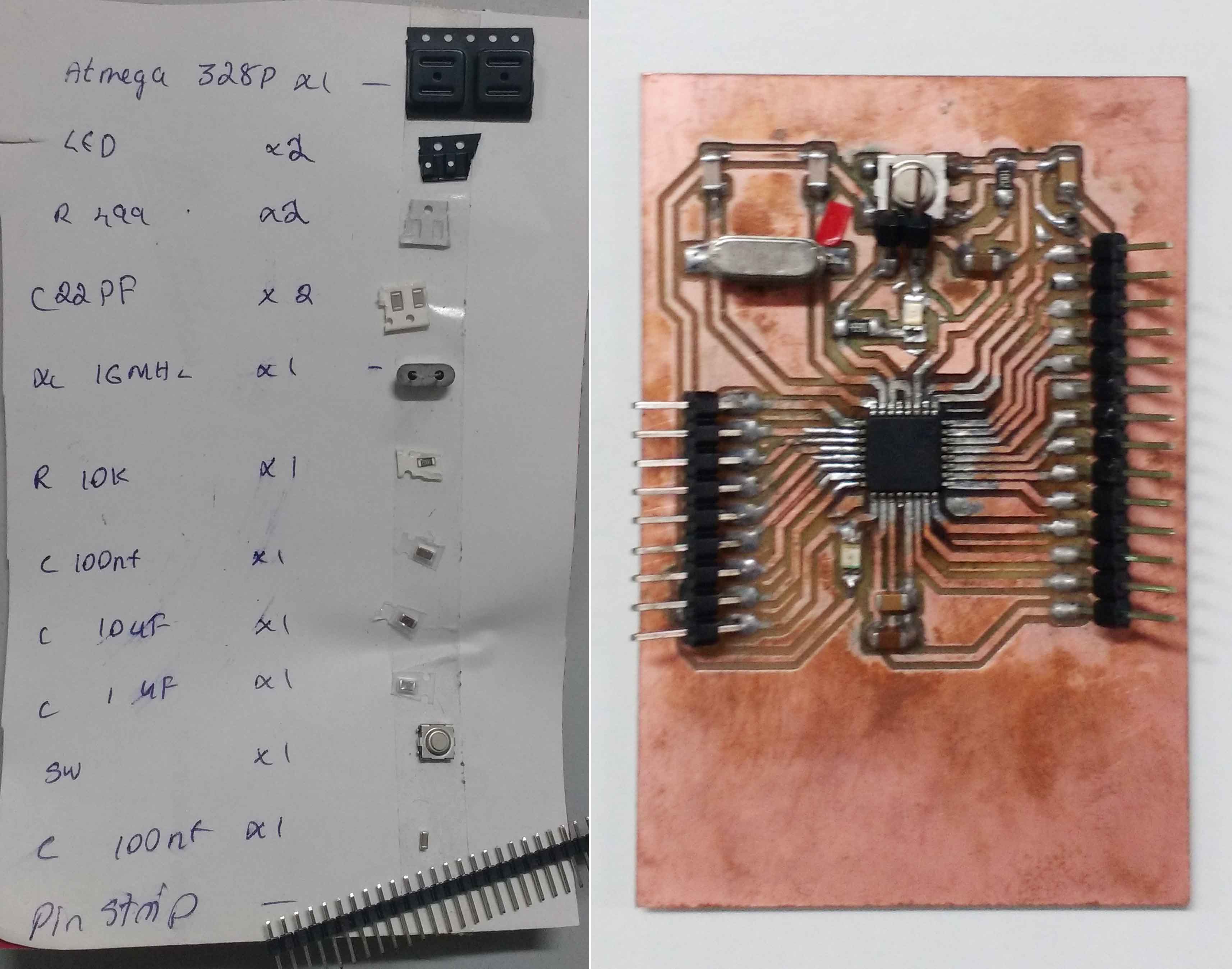
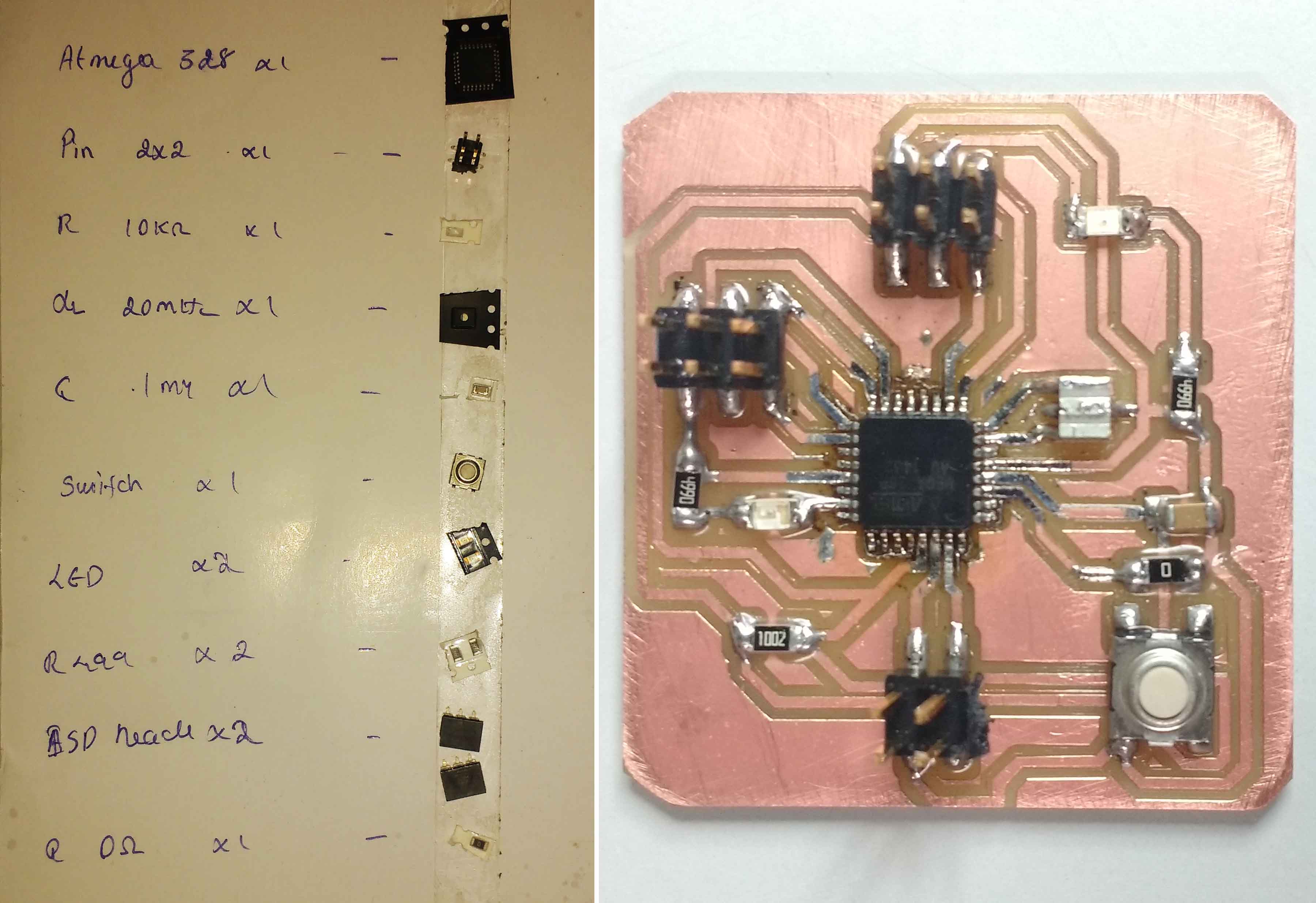
I milled the PCB and Soldered my components to the Board. For details about the PCB manufacturing process please reffer my Week 5 page
The result is .
After completing the board I decided to check the board by uploading bootloader.
Open File ->preference ->additional board management URL
And add the below URL to it.
Again open Tools -> Board -> Boards management
Scroll down to the bottom and click to install MiniCore
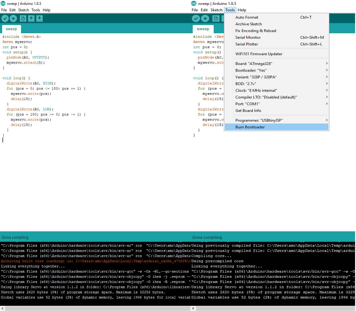
Select Atmega328 from tools -> Board

And select appropriate clock source,Processor and programmer. Burn the bootloader using tools -> Burn bootloader
This is the console output i got.
C:\Program Files (x86)\Arduino\hardware\tools\avr/bin/avrdude -CC:\Users\amc\AppData\Local\Arduino15\packages\MiniCore\hardware\avr\2.0.1/avrdude.conf -v -patmega328p -cusbtiny -e -Ulock:w:0x3f:m -Uefuse:w:0xfd:m -Uhfuse:w:0xd6:m -Ulfuse:w:0b11110111:m
avrdude: Version 6.3, compiled on Jan 17 2017 at 12:00:53
Copyright (c) 2000-2005 Brian Dean, http://www.bdmicro.com/
Copyright (c) 2007-2014 Joerg Wunsch
System wide configuration file is "C:\Users\amc\AppData\Local\Arduino15\packages\MiniCore\hardware\avr\2.0.1/avrdude.conf"
Using Port : usb
Using Programmer : usbtiny
avrdude: usbdev_open(): Found USBtinyISP, bus:device: bus-0:\\.\libusb0-0001--0x1781-0x0c9f
AVR Part : ATmega328P
Chip Erase delay : 9000 us
PAGEL : PD7
BS2 : PC2
RESET disposition : dedicated
RETRY pulse : SCK
serial program mode : yes
parallel program mode : yes
Timeout : 200
StabDelay : 100
CmdexeDelay : 25
SyncLoops : 32
ByteDelay : 0
PollIndex : 3
PollValue : 0x53
Memory Detail :
Block Poll Page Polled
Memory Type Mode Delay Size Indx Paged Size Size #Pages MinW MaxW ReadBack
----------- ---- ----- ----- ---- ------ ------ ---- ------ ----- ----- ---------
eeprom 65 20 4 0 no 1024 4 0 3600 3600 0xff 0xff
flash 65 6 128 0 yes 32768 128 256 4500 4500 0xff 0xff
lfuse 0 0 0 0 no 1 0 0 4500 4500 0x00 0x00
hfuse 0 0 0 0 no 1 0 0 4500 4500 0x00 0x00
efuse 0 0 0 0 no 1 0 0 4500 4500 0x00 0x00
lock 0 0 0 0 no 1 0 0 4500 4500 0x00 0x00
calibration 0 0 0 0 no 1 0 0 0 0 0x00 0x00
signature 0 0 0 0 no 3 0 0 0 0 0x00 0x00
Programmer Type : USBtiny
Description : USBtiny simple USB programmer, http://www.ladyada.net/make/usbtinyisp/
avrdude: programmer operation not supported
avrdude: Using SCK period of 10 usec
avrdude: initialization failed, rc=-1
Double check connections and try again, or use -F to override
this check.
avrdude done. Thank you.
Error while burning bootloader.
Remark! Error ! It showing an erro "initialization failed, rc=-1" Usually it occures when the programmer can't communicate with the microcontroller eg. During connection breaking. I checked every connection connection with multimeter but everything seems to be fine .So I decided to mill a modified satshakit and Check wether the same problem persist
This Github repository contains everything about satshas kit.
After completing the board I tryed to upload the Arduino Uno bootloader but It again shows the same Error !
So i thought It may be something with my programming.
In Arduino if we try to program a virgin atmega328p chip this error may occure . This is because the fuses of a virgin chip is set to use the internal 8 MHz clock with a prescaling of 1/8 . So in effect it will be set to work in a clock speed of 1 MHz .So if we are using a highspeed programmer the Chip may not be able to catchup with it .So may be we need a slowspeed programmer
Though Everybody I refered are using FabISP in my case it is not working with Arduino.So I decided to try it with a slowspeed programmer. Wow! that was a terrible decisions . During that jurney I met with an accident and I had to take a 10 days bed rest. But i could able to get a USBasp programmer. By connecting a jumper in the USBasp programmer I could upload in slow speed .
For safty I connected the board using programmer and uploaded the bootloader for 8 MHz internal oscillator BINGO!!! its working . The fun part is that now both programmers are working.
But there is a problem the programmers are working only while uploading the bootloader . It is strugling with some problems while uploading the program.

I thought thismight be due to some wrong fuse setting . So i decided to manually set the fuses
This allaboutcircuits Page discribes ATmega328P Fuse Bits in details.
Open Powershell and type
Bilow shown are the
Open Powershell and type
PS C:\Users\amc\Desktop\output\Blink2> avrdude -b 19200 -c USBasp -p m328p -v -e -U efuse:w:0x05:m -U hfuse:w:0xD6:m -U
lfuse:w:0xFF:m
avrdude.exe: Version 5.10, compiled on Jan 19 2010 at 10:45:23
Copyright (c) 2000-2005 Brian Dean, http://www.bdmicro.com/
Copyright (c) 2007-2009 Joerg Wunsch
System wide configuration file is "C:\WinAVR-20100110\bin\avrdude.conf"
Using Port : lpt1
Using Programmer : USBasp
Overriding Baud Rate : 19200
AVR Part : ATMEGA328P
Chip Erase delay : 9000 us
PAGEL : PD7
BS2 : PC2
RESET disposition : dedicated
RETRY pulse : SCK
serial program mode : yes
parallel program mode : yes
Timeout : 200
StabDelay : 100
CmdexeDelay : 25
SyncLoops : 32
ByteDelay : 0
PollIndex : 3
PollValue : 0x53
Memory Detail :
Block Poll Page Polled
Memory Type Mode Delay Size Indx Paged Size Size #Pages MinW MaxW ReadBack
----------- ---- ----- ----- ---- ------ ------ ---- ------ ----- ----- ---------
eeprom 65 5 4 0 no 1024 4 0 3600 3600 0xff 0xff
flash 65 6 128 0 yes 32768 128 256 4500 4500 0xff 0xff
lfuse 0 0 0 0 no 1 0 0 4500 4500 0x00 0x00
hfuse 0 0 0 0 no 1 0 0 4500 4500 0x00 0x00
efuse 0 0 0 0 no 1 0 0 4500 4500 0x00 0x00
lock 0 0 0 0 no 1 0 0 4500 4500 0x00 0x00
calibration 0 0 0 0 no 1 0 0 0 0 0x00 0x00
signature 0 0 0 0 no 3 0 0 0 0 0x00 0x00
Programmer Type : usbasp
Description : USBasp, http://www.fischl.de/usbasp/
avrdude.exe: auto set sck period (because given equals null)
avrdude.exe: AVR device initialized and ready to accept instructions
Reading | ################################################## | 100% 0.02s
avrdude.exe: Device signature = 0x1e950f
avrdude.exe: safemode: lfuse reads as 62
avrdude.exe: safemode: hfuse reads as D9
avrdude.exe: safemode: efuse reads as 7
avrdude.exe: erasing chip
avrdude.exe: auto set sck period (because given equals null)
avrdude.exe: reading input file "0x05"
avrdude.exe: writing efuse (1 bytes):
Writing | ################################################## | 100% 0.01s
avrdude.exe: 1 bytes of efuse written
avrdude.exe: verifying efuse memory against 0x05:
avrdude.exe: load data efuse data from input file 0x05:
avrdude.exe: input file 0x05 contains 1 bytes
avrdude.exe: reading on-chip efuse data:
Reading | ################################################## | 100% 0.00s
avrdude.exe: verifying ...
avrdude.exe: 1 bytes of efuse verified
avrdude.exe: reading input file "0xD6"
avrdude.exe: writing hfuse (1 bytes):
Writing | ################################################## | 100% 0.02s
avrdude.exe: 1 bytes of hfuse written
avrdude.exe: verifying hfuse memory against 0xD6:
avrdude.exe: load data hfuse data from input file 0xD6:
avrdude.exe: input file 0xD6 contains 1 bytes
avrdude.exe: reading on-chip hfuse data:
Reading | ################################################## | 100% 0.00s
avrdude.exe: verifying ...
avrdude.exe: 1 bytes of hfuse verified
avrdude.exe: reading input file "0xFF"
avrdude.exe: writing lfuse (1 bytes):
Writing | ################################################## | 100% 0.00s
avrdude.exe: 1 bytes of lfuse written
avrdude.exe: verifying lfuse memory against 0xFF:
avrdude.exe: load data lfuse data from input file 0xFF:
avrdude.exe: input file 0xFF contains 1 bytes
avrdude.exe: reading on-chip lfuse data:
Reading | ################################################## | 100% 0.01s
avrdude.exe: verifying ...
avrdude.exe: 1 bytes of lfuse verified
avrdude.exe: safemode: lfuse reads as FF
avrdude.exe: safemode: hfuse reads as D6
avrdude.exe: safemode: efuse reads as 5
avrdude.exe: safemode: Fuses OK
avrdude.exe done. Thank you.
But I have done something wrong later, maybe uploaded with a wrong fuse now the microcontroller is brick . Maybe some problem with the external oscilator circuit also .Since our desoldering hot air gun is not working currently I forced to mill a new board .mean while I unscrewed the hot air gun and found it is malfunctioning due to the heater coil is broken. Since we can't solder it since it is heating .I made a loop with the wire itself and now its working . Though the heat gun is working now i decided to use the new board anyway.
This time I chose 8 Mhz internal oscilator alone kept the christal unused for future uses only
I burned the bootloader for 8 MHz and tried to manually uploading the skech
Go to file -> Preferences and select Show verbose output during comilation and upload .

Compile the sketch and scroll down the comments in console
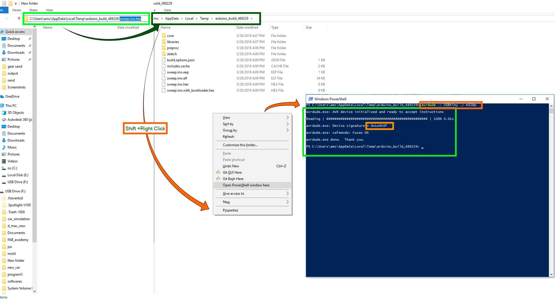
There will be something like "C:\Users\amc\AppData\Local\Temp\arduino_build_489229/sweep.ino.hex"
Copy that
Open a file browser and go to the address.
In the folder open PowerShell by rightclicking while holding the shift key
write a test command check wether the device is working .
Now upload the program
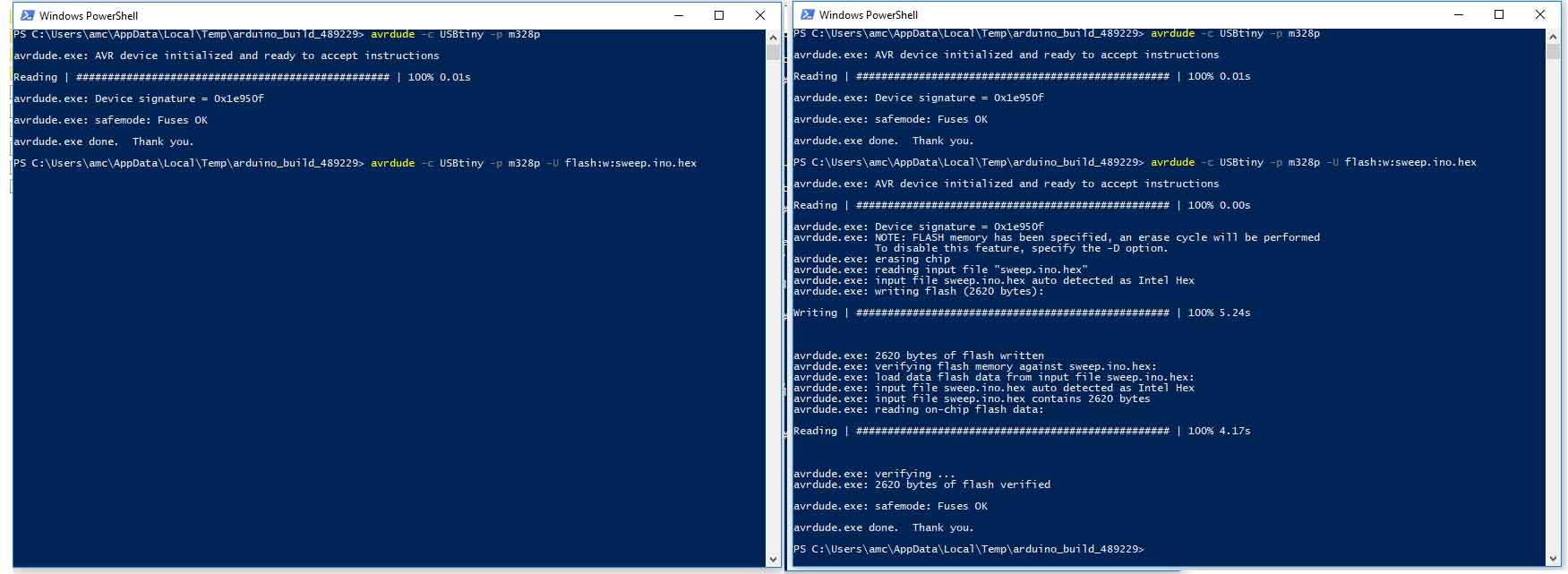
Wow atlast it worked !!!!!
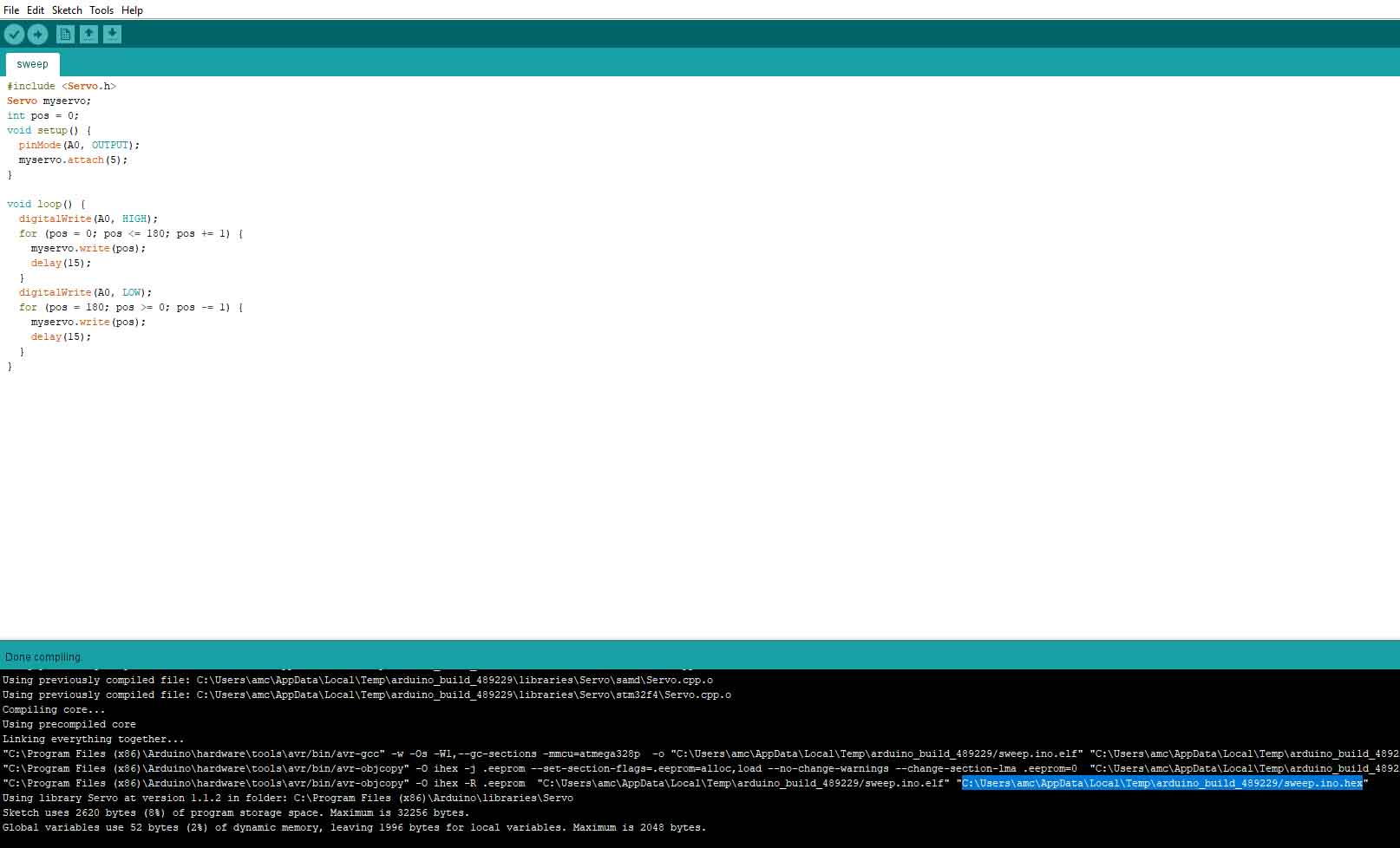
I need to write a program to rotate a servomotor from 0 to 180 and 180 to in small steps also i need to indicate the direction of the rotation by turning on and off an LED. I choose arduino to program.
#include <Servo.h>
Servo myservo;
int pos = 0;
void setup() {
  pinMode(A0, OUTPUT);
  myservo.attach(5);
}

void loop() {
  digitalWrite(A0, HIGH);
  for (pos = 0; pos <= 180; pos += 1) {
    myservo.write(pos);
    delay(15);
  }
  digitalWrite(A0, LOW);
  for (pos = 180; pos >= 0; pos -= 1) {
    myservo.write(pos);
    delay(15);
  }
}
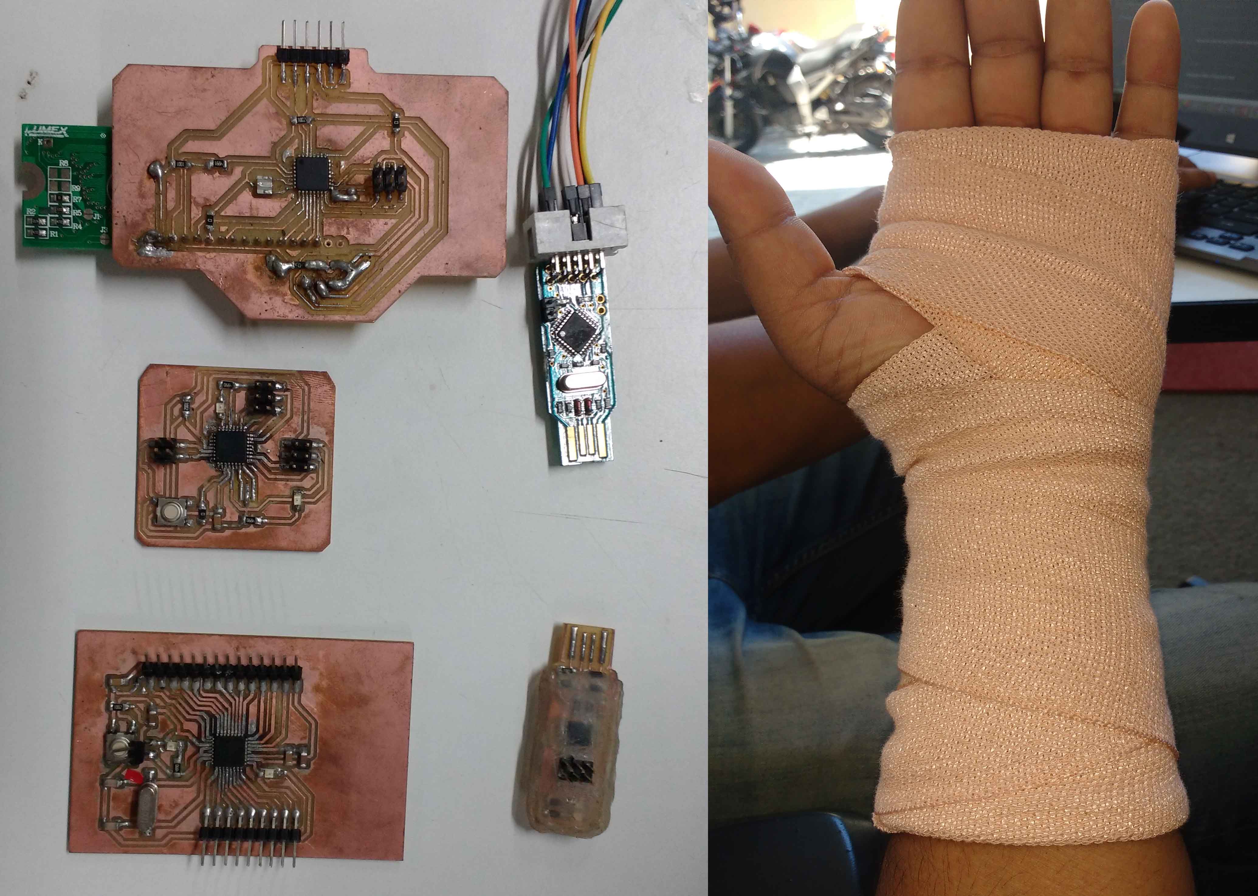
The end result looks like this
And this is the expense of learning
You can download all related Files Here