Final Project (Version 1.0)
You can find Version 2.0 below after version 1.0 downloadable files.
This Project is protected under the (Apache License 2.0) and the text of the licensing can be found Here!

Project Idea ?
My project idea briefly is a chandlier called (Chandella) that detects your existense in the room and you're below it and lights upon it and the variations of colors will be used for photography purposes which will help me a lot in my photography projects and upcoming youtube channel.
What will it do?
The input motion detection sensor once triggered it will use the RGB variation of lights to make different colors that will be used for 2 things: Color Therapy and Portrait photography.
Who's done what beforehand?
During the previous week I've worked as start on a simple vision/design for my final project shape in the Computer Aided Design week.
Then we came to electronics and how to fabricate our boards and when the real work started for my final project was in the Input devices week, by making a board for my motion detection sensor which later on change to be an IR sensor for better detection of someone sitting below it or not not just movement.
Then the most crucial board of them came in the Output devices week which the board that will control my RGB LED strip.
Then I went further in weeks by experimenting the molding and casting week, but I didn't find it that handy to work with it in the final project as the time consumption is too high
Then I experimented in the Wild card week by making a basic frame for the chandlier mixed with Flourscent chemical and this made me realise that probably I'll work using the molding and casting techniques, but the difference that in composite week my horizons was widen about ways to make ENORMOUS molds, but I ended using the composites because it's more easy to make and produce and light in weight as well.
What materials and components (might/will) be required?
In each week there's a bill of material that show's the components used, this is the exploded BOM for the final project.| COMPONENT | COUNT | UNIT PRICE |
TOTAL PRICE |
VENDOR | NOTES |
|---|---|---|---|---|---|
| IR Sensor | 1 | 3.47 USD | 3.47 USD | Deal Extreme | Link |
| Attiny 45 | 1 | 1 USD | 1 USD | Farnell | |
| FTDI headers | 2 | 0.25 USD | 0.5 USD | Farnell | |
| 10K Ohm Resistors | 2 | 0.2 USD | 0.2 USD | Farnell | |
| Connector Header Surface Mount 6 position | 3 | 1.09 USD | 3.27 USD | Digi-Key | |
| 499 Ohm Resistors | 1 | 0.1 USD | 0.1 USD | Digi-Key | |
| 0 Ohm Resistors | 1 | 0.1 USD | 0.1 USD | Digi-Key | |
| Red LED | 1 | 0.25 USD | 0.25 USD | Farnell | |
| MOSFET N-CH 30V 1.7A | 3 | 0.58 USD | 1.74 USD | Farnell | |
| IC REG LINEAR 5V 1A | 1 | 0.50 USD | 0.50 USD | Digi-Key | |
| RGB strip LED | 2.5 meters | 1.12 USD | 2.8 USD | (local Store) MTM Electronics | |
| Capacitor 1uf | 2 | 0.46 USD | 0.92 USD | Farnell | |
| Attiny 44 | 1 | 1 USD | 1 USD | Farnell | |
| Copper Tape | 1 | 3 USD | 3 USD | Farnell | |
| 3D Printing | 1 | 1 Gram = 0.34 USD | 29 Grams = 9.86 USD | Fab Lab Egypt | |
| Power Supply (12V 2A) | 1 | 4.5 USD | 4.5 USD | (Local Store) Maamoon |
What parts and systems will be made?
- Input circuit to control the input device (IR Sensor)
- Control circuit to control the R G B lighting
- 3D printed PCB holder
- Vinyl Cutting to make the voltage (12V, GND) more neat for connections and to have the ability to add another device that could use 12V.
What processes will be used?
- Milling and Soldering the electronics boards
- Composites to make the frame
- To make the composite base frame CNC machining used
- To fix PCB's in their location I used 3D printing
- Vinyl Cutting
Project steps from zero to light!
Frame Designing:
In the Wild Card Week I designed my frame and it was 2D, but because it went through the Computer aided machining I made it as a 3D part.
I also designed 3D printed pcb holders to stick the PCB's to the frame and avoid the slipping of them from the frame.
First, I drawed two arcs to make something looks like a shell over the orbits.
then I drew a square with exact dimensions to fit with the Output devices week PCB including the holes that will help me fix the 3D printed part and the already made holes in the output circuit.


it doesn't look the best thing in the world, but it does its desired functionality


Frame Making:
In the Wild Card Week I described in detail how I made my frame out of foam and medical bandage coated with epoxy and added a luminating in the dark chemical to make the frame cool even if there's no light in it.Without UV light:
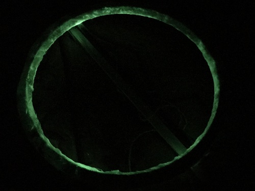
With UV light:
.JPG)
Electronics Making: (Input Device)
In Input devices week I made my board which's compatible with any 3 pins sensor (GND, Signal, VCC) at first I thought I would use PIR sensor to detect motion and upon it the chandella should light up!
I knew later on that my project needs IR sensor to change chandlier colors and could also detects if someone sitting below it to take a photo.

Electronics Making: (Output Device)
In the Output Devices week I made one of the interesting and beneficial boards I've ever made to control the RGB strip light. I started soldering my IDC cable un-isolated part to the terminals of the RGB strip led and to the female power connector that I plug my external power source to.

Then I used electrical isolation tape to avoid wires touching each other and making short circuit.


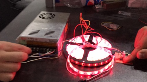
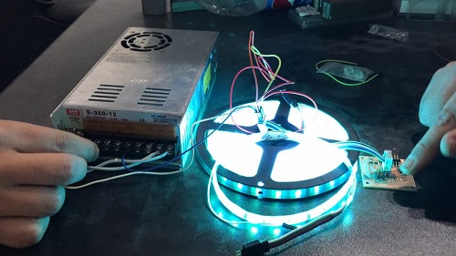
Note: The fingers on the board is used to sense the heat in case of any high temperature occurance from the MOSFETs or the Voltage regulator.
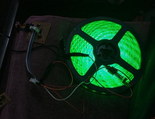
In this last photo you can see in the top left corner the board is powered up (after being programmed) only using single IDC cable that's connected to wall outlet.
Communication between boards:
As I reached this far I needed to make my Input board to communicate with the output board and it was pretty easy task, because I've learnt a lot in the Networks and Communication week and transfered this knowledge to communicate between the boards easily. The purpose of the code is when the IR sensor is triggerd send a signal with a different letter each time to the output board so the colors change and they're pre-set with the most common lightings I need to photograph someone/something.- R: Makes the entire strip red colored
- G: Makes the entire strip green colored
- B: Makes the entire strip blue colored
- Y: Makes the entire strip Yellow colored
- P: Makes the entire strip light violet colored
- V: Makes the entire strip heavy violet colored
- W: Makes the entire strip white colored becuase it turns on the Red, green and blue lights
- Z: Makes the entire strip fades smooooothly from white colored to OFF state (I can do that because I'm connecting the pins on PWM pins so I can give values from 0-255 and use loops to control them.
Master Code:
#include <SoftwareSerial.h>     // This is a library that make us initialize the communication to use the TX & RX pin.
#define RX    1                 // This the pin I'll use later on to receive the confirmation message from the slave board.
#define TX    2                 // This the pin I'll send my data through, to the slave board.

SoftwareSerial Serial(RX, TX);  // giving the pin variables to the softwareSerial library after defining them in the line upward.

int val=0;                      // variable to store the values coming from the reading process.
int flag=0;                     // variable to used as a condition to switch between colors for several IR signals.
void setup()
{
  Serial.begin(9600);           // define the baud rate that the communication will start on.
  pinMode(3,OUTPUT);            // set the pin connected to the board LED as output to give it (0v or 5v)
  pinMode(4,INPUT);             // set the pin connected to the the sensor as input to receive signal from (0:ON or 1:OFF)
}
void loop() {
//#########################################Sending Data to Slave#########################################

 val = digitalRead(4);          // read the input pin and store it in "val" variable.
 if (val == 0) {                // checks if the variable "val" value is 0:ON, and turns the LED on the board which means will start colors picking.
  flag++;                       // Increase flag variable by 1 ( same as " flag = flag + 1; )
  digitalWrite(3,HIGH);         // turning the LED on on the input board, which gives me an indication that the value is incremented successfully.
  delay(1000);                  // delay used to read every second not all the time to allow changing colors value easily and avoid skipping ones because of the read speed.
  if (flag == 1) {              // checks for the flag value to send the corresponding message.
  Serial.write('R');            // Sending a message using the TX pin that the slave board will receive and turn on the corresponding color for each letter.
  }
   if (flag == 2) {             // checks for the flag value to send the corresponding message.
  Serial.write('G');            // Sending a message using the TX pin that the slave board will receive and turn on the corresponding color for each letter.
  }
  if (flag == 3) {              // checks for the flag value to send the corresponding message.
  Serial.write('B');            // Sending a message using the TX pin that the slave board will receive and turn on the corresponding color for each letter.
  }
  if (flag == 4) {
  Serial.write('Y');            // Sending a message using the TX pin that the slave board will receive and turn on the corresponding color for each letter.
  }
  if (flag == 5) {              // checks for the flag value to send the corresponding message.
  Serial.write('V');            // Sending a message using the TX pin that the slave board will receive and turn on the corresponding color for each letter.
  }
  if (flag == 6) {              // checks for the flag value to send the corresponding message.
  Serial.write('P');            // Sending a message using the TX pin that the slave board will receive and turn on the corresponding color for each letter.
  }
  if (flag == 7) {              // checks for the flag value to send the corresponding message.
  Serial.write('W');            // Sending a message using the TX pin that the slave board will receive and turn on the corresponding color for each letter.
  }
  if (flag == 8) {             // checks for the flag value to send the corresponding message.
  Serial.write('Z');           // Sending a message using the TX pin that the slave board will receive and turn on the corresponding color for each letter.
  flag=0;                      // sets the flag value to zero in order to star the sequence/pattern all over again.
  }
 }
  else {
  digitalWrite(3,LOW);          // turning the LED off on the input board if there's no reading comming, and lets me know when I can increment to the next value.
  delay(1000);                  // delay used to read every second not all the time to allow changing colors value easily and avoid skipping ones because of the read speed.
 }
}
Slave Code:
#include <SoftwareSerial.h>   // This is a library that make us initialize the communication to use the TX & RX pin.
#define RX    4               // This is the pin that will receive the data from the Master board to turn on the LED.
#define TX    1               // This is the pin that will send the

#define R_PIN 8   //Pin coming from the N-MOSFET to the ATTiny pins and corresponds to the Red light.
#define G_PIN 6   //Pin coming from the N-MOSFET to the ATTiny pins and corresponds to the Green light.
#define B_PIN 7   //Pin coming from the N-MOSFET to the ATTiny pins and corresponds to the Blue light.

SoftwareSerial Serial(RX, TX); // giving the pin variables to the softwareSerial library after defining them in the line upward.
int ser = 0;        // variable to store the values coming from the serial reading process.
void setup()
{
  Serial.begin(9600);         // define the baud rate that the communication will start on.
  pinMode(R_PIN, OUTPUT);     //Defining the LED strip pins as output
  pinMode(G_PIN, OUTPUT);     //Defining the LED strip pins as output
  pinMode(B_PIN, OUTPUT);     //Defining the LED strip pins as output
}

void loop() {
//#########################################Receiving data from the Master#########################################
  if (Serial.available()) {   // if there's any data coming to the RX pin.

  ser = Serial.read();        // Read it and store this data in the variable "ser".

                              // (Low Intensity : 100) (High Intensity : 200)

  if (ser == 'R') //Red            //Verify that the data received from the master board and act upon the letter received.
  {
    analogWrite(R_PIN,200);   // turning the Red pin on.
    analogWrite(G_PIN,0);     // turning the Green pin off.
    analogWrite(B_PIN,0);     // turning the Blue pin off.
}

if (ser == 'Y')   //Yellow          // Verify that the data received is S from the master board and act upon it.
  {
    analogWrite(R_PIN,100);  // turning the Red pin on.
    analogWrite(G_PIN,100);  // turning the Green pin on.
    analogWrite(B_PIN,0);    // turning the Blue pin off.
}

if (ser == 'G')    //Green         // Verify that the data received is S from the master board and act upon it.
  {
    analogWrite(G_PIN,200);  // turning the Green pin on.
    analogWrite(R_PIN,0);    // turning the RED pin off.
    analogWrite(B_PIN,0);    // turning the Blue pin off.
}

if (ser == 'B')   //Blue          // Verify that the data received is S from the master board and act upon it.
  {
    analogWrite(B_PIN,200);  // turning the Blue pin on.
    analogWrite(R_PIN,0);    // turning the RED pin off.
    analogWrite(G_PIN,0);    // turning the Green pin off.
}

if (ser == 'P')     //Light violet    // Verify that the data received is S from the master board and act upon it.
  {
    analogWrite(B_PIN,100);  // turning the Blue pin on.
    analogWrite(R_PIN,100);  // turning the Red pin on.
    analogWrite(G_PIN,0);    // turning the Green pin off.
}

if (ser == 'V')    //Heavy violet         // Verify that the data received is S from the master board and act upon it.
  {
    analogWrite(B_PIN,200);  // turning the Blue pin on.
    analogWrite(R_PIN,200);  // turning the Red pin on.
    analogWrite(G_PIN,0);    // turning the Green pin off.
}
if (ser == 'W')  //White           // Verify that the data received is S from the master board and act upon it.
  {
    analogWrite(B_PIN,220);  // turning the Blue pin on.
    analogWrite(R_PIN,220);  // turning the Red pin on.
    analogWrite(G_PIN,220);  // turning the Green pin on.
}
if (ser == 'Z') //Slowly fades from white to OFF // Verify that the data received is S from the master board and act upon it.
  {
    for (int i=200; i>=0; i--){ // loop that decrements from 200 to 0 in the 3 colors (R,G,B)
    analogWrite(B_PIN, i);  // decrementing the Blue pin value.
    analogWrite(R_PIN, i);  // decrementing the Red pin value.
    analogWrite(G_PIN, i);  // decrementing the Green pin value.
    delay(20);              // delay to smoothen the fading. ;)
    }
}}}
Assembly:
I had to assemble my 3D printed part and my Output PCB which's the core PCB the input one is not that important for me to fix in a certain place.

Then I mounted it as I designed on the frame and added couple of wires for (VCC,GND,SIGNAL) between the boards, and the extending wire that contain the (VCC,GND,SIGNAL) for the IR sensor.
.jpeg)
After putting the wires and fixing the IR sensor I was still in doubt whether I should fix the Input board using anyway or not, yet it was almost not moving, so I guarnteed that it won't move by making a small slot for it in the 3D printed part using a wire clipper.
.jpeg)
.jpeg)
Wire Clipper:

I previously had 4 hook screw, so I used them to wrap the RGB strip around the frame, without falling and getting loose.


After doing I recalled that I wasn't 100% satisfied by my IDC 12v supply wiring because I'm intending to to add my UV light neon lamp to the project in the future so I want to be able to add more things that work on the 12v powersupply specially that I barely consume half of the current it can give (1A usage from 2A supply).
Vinyl cutter:
So what I did basically is what I exactly described in the Computer Controlled Cutting week in the video that I explained how to import a photo and get the vinyl cuttter to cut it.
I brought flexible copper and cut it as arcs which's a bit fancy thing you can cut it as short strips which I found later on to be better for general purpose usage in case you changed your mind.

and after drawing the part roughly on SolidWorks I exported it as (.DXF) file and from that file I used illustrator on one of my friend laptops and exported them as JPG to import it on RolandCut studio.(Solid Part, PNG and .CST (Roland machine format) are included in the download files)

Note: you can change the arc dimension by clicking right click then properties (Alt+Enter)


After Cutting:


The reason you might ask yourself why I cut a lot of arcs not only the two ones I'll need, honestly because it's my first time using it, so I made failure tolerance and added some for experimenting later :D
So in the picture below I've soldered the VCC terminal to the copper and the other one was soldered and extended by a wire that layed under the GND copper tape.

To differentiate between positive and negative terminal later on without using AVO meter I used extra copper tape to make on the VCC Copper tape a "+" sign.

Almost done with the assembly WOHOO!

I started after finishing the frame electrical connection I had to hang the frame using a wire, but to provide a wire that can hold this frame (Which's pretty light btw) but transparent and doesn't affect the over all shape that much, I used Nylon string that's normally used for fishing.

Then I connected each two hook screws together to make some sort of triangle to hang the frame from and because I have only two already made holes up in the wall also (because I didn't have enough nylon string :D)

reaching this point i've successfully finished the chandelier assembly and its integration with other parts.
Hanging Area Setup:
WARNING: DON'T TRY IF YOU DON'T HAVE EXPERIENCE WITH HIGH VOLTAGE SAFETY PRECAUTIONS!!
This part I literally thank god I'm not dead or burnt the house while doing it.
At the beginning I had a a fluorescent lamp in the room, so I decided to remove it and add a female power outlet socket.


NOTE: use avometer to check there's 0 electricity going through the live wires, and try to make an open circuit with your body in case of any saftey faults, again I don't advise you to do that on your own!
I opened it and fixed a short wire to fix them to the main house supply wires.

after connecting the wires I made from the female socket to the house's live wires, I wrapped both wires seprately using electrical tape I used before to avoid electrical short circuit that can blow up the house and take my life with it :'D

After doing this I felt that the wire I made for it is too long, so I shorten it and used electrical tape to hold the folds I made.
However, I did that to the power supply cable too!, but with much cooler way.
I brought the Nylon string wheel after finishing it, and wrapped the wire around it and I almost only let the length I wanted out as you can see.

After finishing the hanged socket part I need something to hold the triangles I made in my frame so I brought two more hook screws like the ones I used earlier to fit in the wall (The holes was already there to fix the old fluorescent lap to the wall)

Then I hanged the chandelier as shown below:
Note: The chandelier might looks a bit tilting towards a certain edge, that's because the triangles are not equally made because I couldn't tie the nylon string probably, but if I did it was going to be perfectly horizontal.

Results:
White color from chandella vs. Blue. (Excuse picture quality due to resizing)
(Stairs).jpeg)
(Stairs).jpeg)
.jpeg)
.jpeg)
.jpeg)
Violet:
.jpeg)
Purple:
.jpeg)
Download Files:
SolidWorks Files for design.PCB Holder (.stl) File
Vinyl Final Project Files
Eagle Input Board Files & Milling Pictures (Try 1 & 2) (Try 1 is a failure, use Try 2)
Eagle Output Board Files
Arduino Codes:
Final Project (Version 2.0)
I was pointed by both Neil Gershenfeld and my global evaluator Francisco to change the the old version design because it was poorly wrapped around the orbit and it doesn't have an artistic side.
So I started the process all over again with a new firm design to improve some points which considered as drawbacks in the old design:
- There's no groove or rail the led strip can fit in and wrapped around the chassis neatly.
- Electronics is not organized and not modular (not easy to replace board)
- The design lacks good finishing because of the irregularity of the composite design.
- Also It's way easier to reproduce this design and could be commercialized easier than the previous version.
New Bill of Materials:
Note: Highlighted items are the new ones.
| COMPONENT | COUNT | UNIT PRICE |
TOTAL PRICE |
VENDOR | NOTES |
|---|---|---|---|---|---|
| IR Sensor | 1 | 3.47 USD | 3.47 USD | Deal Extreme | Link |
| Attiny 45 | 1 | 1 USD | 1 USD | Farnell | |
| FTDI headers | 2 | 0.25 USD | 0.5 USD | Farnell | |
| 10K Ohm Resistors | 2 | 0.2 USD | 0.2 USD | Farnell | |
| Connector Header Surface Mount 6 position | 3 | 1.09 USD | 3.27 USD | Digi-Key | |
| 499 Ohm Resistors | 1 | 0.1 USD | 0.1 USD | Digi-Key | |
| 0 Ohm Resistors | 1 | 0.1 USD | 0.1 USD | Digi-Key | |
| Red LED | 1 | 0.25 USD | 0.25 USD | Farnell | |
| MOSFET N-CH 30V 1.7A | 3 | 0.58 USD | 1.74 USD | Farnell | |
| IC REG LINEAR 5V 1A | 1 | 0.50 USD | 0.50 USD | Digi-Key | |
| RGB strip LED | 2.5 meters | 1.12 USD | 2.8 USD | (local Store) MTM Electronics | |
| Capacitor 1uf | 2 | 0.46 USD | 0.92 USD | Farnell | |
| Attiny 44 | 1 | 1 USD | 1 USD | Farnell | |
| Copper Tape | 1 | 3 USD | 3 USD | Farnell | |
| 3D Printing | 1 | 1 Gram = 0.56 USD | 15 Grams = 8.4 USD | Fab Lab Egypt | |
| Spray paint | 2 | 0.95 USD | 1.9 USD | wall paint and tools shop | |
| 3mm plywood | 5 | 2.79 USD | 14 USD | Fab Lab Egypt | |
| Power Supply (12V 2A) | 1 | 4.5 USD | 4.5 USD | (Local Store) Maamoon |
Redesigning:
My design Idea was simply because one of the things I learnt through years that simplicity in designs always wins!
so I made 2 Circles with sector cut from both of them to with the same internal diameter,but different external diameter to act as a groove for the LED strip.


Here's the grove made due to difference in outer diameter between the two circles:

Also, there's a slight difference between the two circles if you noticed which will be used as a junction to hold the 3D printed part I made for the electronics.


As you saw in the previous pictures there's 2 holes in almost every 45 degree in both circles that I'll use for aligning layers over each other and hanging the chandlier later on so I made 2 parts one for the alignment and the second one is for stopping the layers from simply falling and not stick together.


Here's how it's assembled:


The final part I needed to add is the part that will contain the PCB's and at the same time make a sneaky entrance for the power and control cable to the circuits without having to much cables that can be seen by eye, So I made a sector that fills the gap in my circle with holes for fixing the part with original chassis and will act as a second layer with the long screw to hold my PCB.


The assembled version:

Manufacturing & Assembly:
The manufacturing part of this design was way easier because it's not as hard as composites I must admit that.
Laser Cutting:
I cut my frame on a 3mm plywood (I had to cut several times to make the desired thickness) on laser cutter with bed size (75cm*90cm) to fit my design which's 50 cm diameter.


After putting the layer on top of each other; I added the locking parts to hold them tightly.


3D printing
I 3D printed the remaining part to complete the circle.


Sparying
I sprayed the entire chassis with white color give it a nice soothing color also, the white color reflect all colors and doesn't absorb them like the black for example.
Note: Make sure you're in well ventilated area or an open area and spary each face several times each time spary gently from a approx. 20 cm distance away then let it dry and repeat the process, this gives much smoother finish than spraying close to the material and will take more time to dry.


Electronics:
I put both boards in the 3D printed part and wired them with only the sensor fixed away from the 3D printed part.

Vinyl:
I made the same arc shaped vinyl cutted flexible copper I used in version 1 to put the female power cable.

Hanging
Finally I used fishing string yet I made fixed wire length for each holder to ensure I have all the flexiblity of hanging it from the ceiling.

Results:


Download Files:
Version 2 Design FilesAcknowledgement:
- My Local Instructors:
Mohamed Abu Elhaggag all this wouldn't have been done without your sincere guidance, support and your most appreciated dedication, you were a friend, father and mentor through the ups and downs even in ones not related to the academy.
May Eldardiry, your support and documenation comments is what made this project looks like what it like and she was always pushing me to work harder and to tolerate the long, but must to gain journey.
- My colleagues: It was my pleasure to work with you all, Haithem Abdelkhalek
you documentation and way of thinking was inspiring for me through the academy work, which I believe I learnt from and will help me later on to be such an organized person.
- Khaled Youssef your help to change my mindset from over complicating things that doesn't work at end was one of the reasons I'll graduate today, and I'll NEVER forget when you lent me your soldering station, and the numerous times that you helped me even with a simple word of optimism I'll be forever thankful for that act kind :')
- Mrehan Elshehawy Although I know you years earlier, you proved by years that you're a really kind pure hearted person and can't be thankful enough to know someone like you and your experienced husband Mahmoud with all support he gave to me.
- Omar Okasha (aka. Okasha) we were journey buddies and we became friends more than a colleague, and our late night food we ate together along with your always complex yet joyful ideas, Thank you.
- Finally my family (The Best for the last): Thank you for your continious support and motivation during this long journey, thanks for helping me in this journey despite our problems nowadays, which I hope it will end soon :')
ENDLESS LOVE