Output devices
In this week we were asked to design, mill and program a board that gives a tangeable output, such as: moving a motor (Physical), making sound using a speaker (Audio) or maybe control a LED (Visual).
Furthermore, I decided to make my own board in order to control my RGB strip LED tha will be used in the final project.
Design
I'll talk briefly about my process,using Eagle software as usual.
Components and Tools:
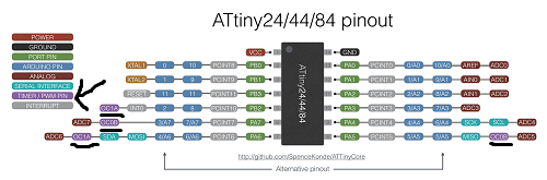
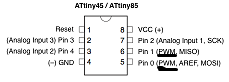
- 1 x ATTiny 44 (Not 45 because I needed more than 2 PWM pins to control the 3 colors.)
- 1 x FTDI headers
- 1 x Capacitor (1uf)
- 1 x Resistor (10k ohm)
- 1 x AVRISP (2x3) header
- 1 x (2x3) header
- 1 x Resistor (0 ohm)
- 3 x NMOSFET
- 1 x Rgb strip LED (5m)
- 1 x Voltage regulator SOT-223 (1A Because the strip consumes 800mA when supplying full power to the RGB strip)
- 1 x Roland Modela MDX-20
- 1 x Soldering Station
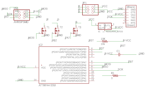
Wiring:
I connected the wires as shown below after reading schematics of the voltage regulator and the N-MOSFET.
- In: the high voltage coming from the power supply. (Which's 12 Volts in my case)
- GND: shares the common GND with the entire board.
- Out: the regulated voltage (Which's 5V)
- Gate: which's the pin that controls the flow of voltage from the Drain to the Source
- Drain: is the positive source which once connected by a signal from the gate the circuit becomes closed.
- Source: which's connected to the GND.
Website Reference
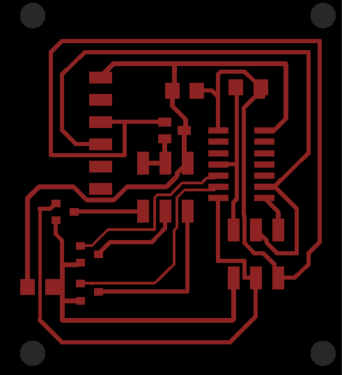
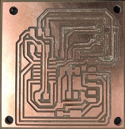
Board Layout:
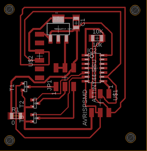
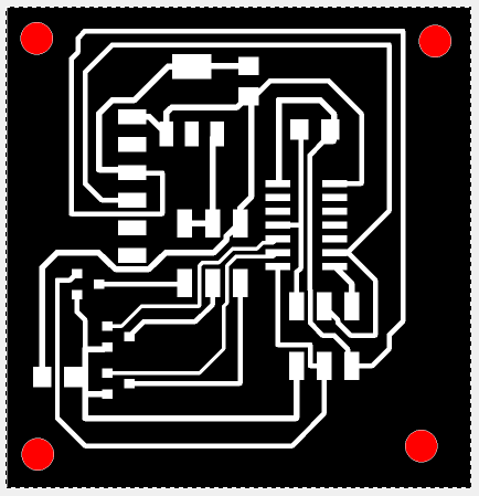
In order to export the board WITH the holes drew you have to make sure those layers are the visible ones:
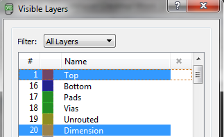
and in order to export our board using GIMP as usual there's a different process due to holes addition in GIMP.
First, select all (CTRL-A) then open a new image (CTRL-N) and paste the clipboard in it (CTRL-V).
Second, color the holes into strong Red (Because this's the completely opposite color to black which saves a step).

Third, click on Colors Tab --> value invert NOT invert for 2 times.
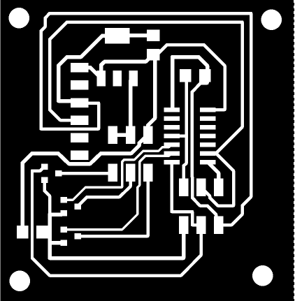
.png)
(Interior).png)
You might wonder why I added or how I added the holes?
Why? Because later on I believe I'll need to fix the board into any material using wood. How?
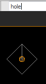
1- search for hole tool.
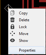
2- right click on the hole you made and click on properties.
3- change the dimension as you want it (Make sure from the grid that you're working with the unit desired for example mm) (2.9 to make sure that the hole is tight for a 3mm screw )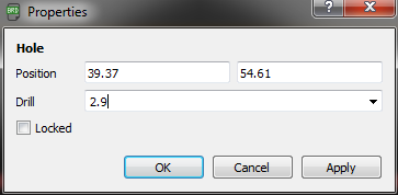
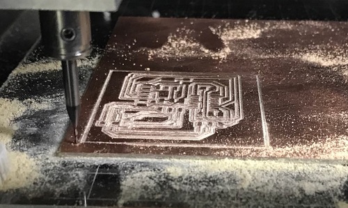
Results before coding:
Coding:
I used arduino to program my board as usual like I did in my Electronics Desgin week.
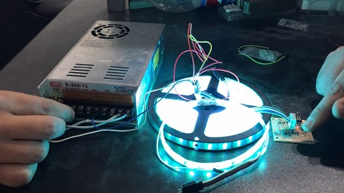
My code purpose was to get the minimum to maximum range of colors using the 3 colors in the LED strip, so I made a code that increments 1 in each color every 0.25 sec. until it gets the maximum brightness.
#define R_PIN 5   //Pin coming from the N-MOSFET to the ATTiny pins.
#define G_PIN 6   //Pin coming from the N-MOSFET to the ATTiny pins.
#define B_PIN 7   //Pin coming from the N-MOSFET to the ATTiny pins.

int R=0, G=0, B=0;   //initializing 3 varibales for the (Red, Green, Blue) variations

void setup() {

  pinMode(R_PIN, OUTPUT);   //Defining the LED strip pins as output
  pinMode(G_PIN, OUTPUT);   //Defining the LED strip pins as output
  pinMode(B_PIN, OUTPUT);   //Defining the LED strip pins as output

}
void loop() {

  for(int i=0; i<250; i++) // loop that increments the value/brightness of each LED strip pin simultaneously by 1
  {
    analogWrite(R_PIN, i);
    analogWrite(G_PIN, i);
    analogWrite(B_PIN, i);
    delay(250); // delay to observe the change of brightness.
  }
}
Results After Coding:
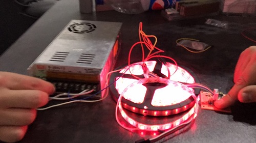
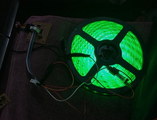
Note: The fingers on the board is used to sense the heat in case of any high temperature occurance from the MOSFETs or the Voltage regulator.
Download Files:
Eagle Design FilesArduino Code