Computer-Controlled Machining
This week purpose is to get familiarized with the usage of CNC router machine in your Fab Lab which eventually will open a sea of possibilities for projects that you can make.
Designing:
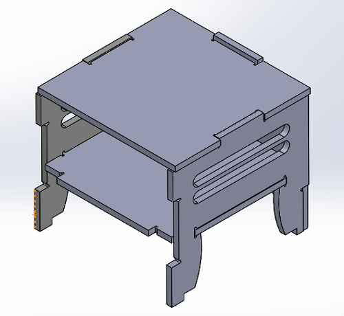
The idea is to make beside table to put my mobile while it's charging, glasses, and my wallet. I needed a standard dimension beside table as I need to use it while I am sleeping on my bed. I started by browsing the opendesk website and choose a beside table suitable for taking the general design concept and the outer dimensions (450mm(L)*405mm(H)*450mm(W)), so I decided to to download the design (.dxf)
Then I started drawing my design parametrically using SolidWorks with reference from the (.dxf) file for the dimension.
The only difference between designing something to be cut on a laser cutter for example and the CNC router is that cnc router end mill have a non-negligible with (For Example, my end mill is 6mm diameter)
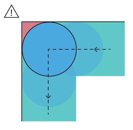
If you didn't use dogbone this will happen: (on the left)
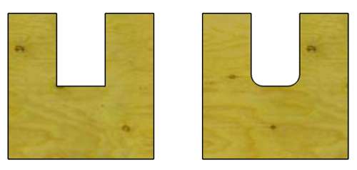
you have to do it anything like this to fit like shown:
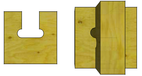
and to save effort on myself while designing I made something called the solid works block
which's something could be resized or copied and pasted several times in the sketch or other solid works you might design in the future.
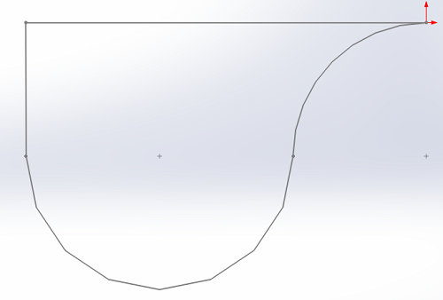

After finishing the design and Assembly you have to export each part as a (.dxf) file and you can refer to the Computer Controlled Cutting week under the Laser cutting part.
Generating ToolPath
After having the (.dxf) files we use a software called ArtCam (9 is the version I'm using) to generate the toolpath for the CNC Router:
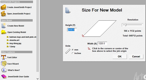
- First Create new model with the dimensions of your CNC router bed or the material you're using dimensions if smaller than the bed.
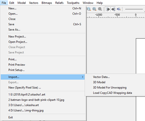
- Then you import your (.dxf) files as vector data
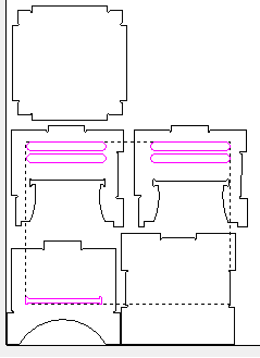
- After that click on 2D profiling to create and select whether the tool path will be from the inside or outside:
- Inside: this means that the end mill will move from the inside of the selected part to avoid increasing the size of whatever it cuts.
- Outside: this means that the end mill will move from the outside of the selected part, so to make the dimension accurate it cuts extra from the material (relative to the the end mill dimension).
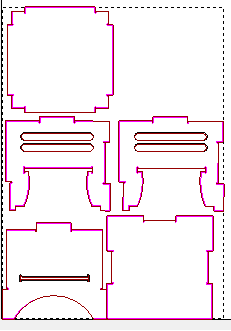
- Select the inner parts of the design
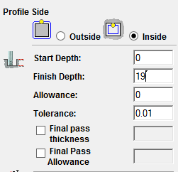
- In the photo below you have several setting to edit and the rest could be left untouched.
- Inside or Outside: based on what've you selected and here it's Inside
- Finish Depth: Start with editing this value relative to the material thickness, and it's adviced to add 1 or 2 mm extra to ensure that the part is totally cut and to avoid any leveling issues if the material is bent.
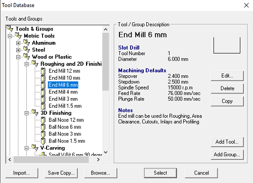
- Select Profile Tool: (Mine was 6mm diameter endmill)
- After selecting the tool you have to edit some parameters: (Optional means you can leave it as default)
- Stepover (optional):The distance the tool will move horizontally when making the next pass. This value should be some fraction or percentage of the tool's total diameter, and is generally in the 25-40% range.
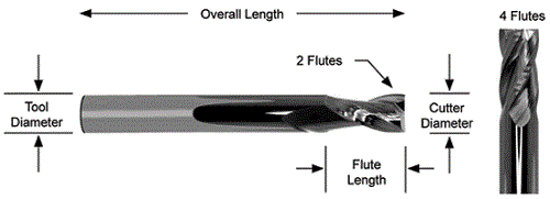
- Stepdown:The distance the tool will move vertically when performing the next Z-pass, also means how many times the part will be cut (18 mm thickness material with 4mm Stepdown = 4.5 times each part), but you have to compromise between minimizing the time and making the value higher which might break the Endmill. Also, make sure the Flute-Length (The exposed part from the endmill outside the spindle shaft shown in the photo below) is more than the total material thickness
- Feed Rate: (Optional)This is the lateral rate of motion of the cutting head as it traverses the material during cutting operations.
- Plunge Rate: (Optional)Like feed rate, this is the rate at which the cutting head moves, but in this case only when plunging, or drilling, into the material.
- Spindle Speed: (Optional)The rotating speed of the cutting tool, defined in revolutions per minute (rpm). This is how fast the milling tool spins as it cuts.
- For more details and explanation please refer to this reference.
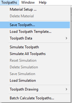
- Then you to scroll down to save the toolpath to work on the other toolpath.
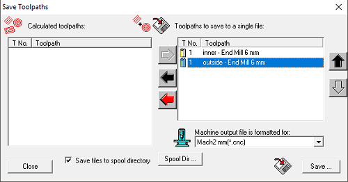
- Then you have to save the toolpath and convert to (.cnc) format as a gcode to make the machine work with it.
- The sequence of what you put first on the left side menu matter because you could import the left side into 2 files. or start with the inside trace then outside (Because if you make the opposite the part is already became cut from the bigger fixed sheet, so the inner parts won't be made correctly)

Machine control:
In the previous steps I have exported the (.cnc), but when we put the file on the device connected to the machine we need another software to translate the (.cnc) file into motion for the 3 axis (a CAM software).
We use NC Studio to control the The CNC router we used the Lab, data about it could be found here, but briefly the technical specification of it are:
- Size = 130 CM x 250 CM
- Spindle Power = 3 / 6 / 7.5 / 9 kw
- Origin = HSD Italy / HQD China
- Cooling = air Cooling
- Voltage = 220 - 380 V
I'll explain briefly what are the essential controls you'll need while working with NC Studio:
First you have to load your file: File Menu ----> Open and Load (Ctrl+O)

- Set Origin: after using the manual movement panel you should click on this button to set the point you're standing on as point to start the process from.
- Move to Origin: if you've alread set the origin previously you can click on this button to move to the X-Y-Z set before.
- Simulate: this simulates the cuttin tool path on the screen below.
- Run: after setting the origin you should hit this button to start the cutting operation.
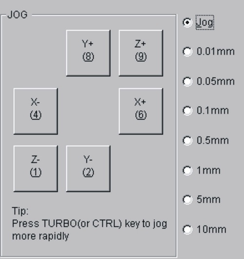
- In the picture below:
- On the right:can control movement of the each axis in both directions
- On the left: is the speed/step of each press you'll click on the right side button (Jog/Ctrl-Jog is the fastest option)
Machine Bed:
First of all the machine bed should have what's called sacrificial layer/sheet which's a layer above the metal sheet.
Secondly, you fix your desired to be cut sheet over it with screws all over the edges to make sure the sheet won't move from the vibrations or the spindle while cutting.
Results:
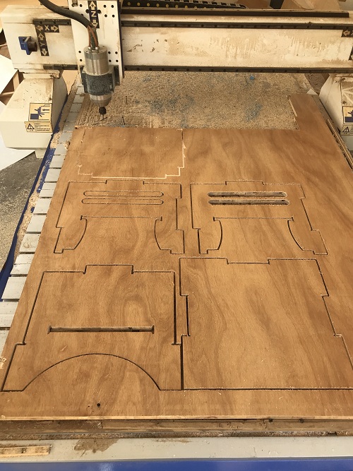
I hammerd the parts as an extra measure to ensure the're fixed together properly and used sand paper to chamfer any edges I felt the're a bit sharp.
Downloadable Files:
SolidWorks Files + (.DXF) + Equations + 2 Solid BlocksRouter Tool Path