Computer-Controlled Cutting
Introduction
We were asked to do two things for this week assignment.
First, to cut something on vinyl cutter (Stickers machine)
Secondly, to design and cut a press fit construction kit, and you might wonder what this means ?
Press fit construction kit: is something that's somehow similar to the LEGO bricks, yet this one from 2D parts so you design a particular item and cutted several times with some small parts to assemble different types of shapes.
Vinyl Cutter:
A vinyl cutter is a type of computer-controlled machine. Small vinyl cutters look like computer printers. The computer controls the movement of a sharp blade like a knife. This blade is used to cut out shapes and letters from sheets of thin self-adhesive plastic (vinyl)
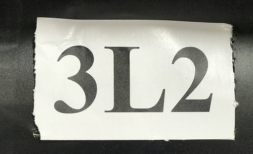
I choose to cut this inside joke (3 L 2) letters
I used CutStudio software that's provided by Roland to cut my letters and here's how:
If you have an image and want to convert it not text from the software:
Using the machine:
First you have to select whether it's a Roll or a Piece
Roll: measures only the width of the roll yet doesn't measure the length.
Piece: he assumes it's a small tight piece for your work so he measures the width and the length.
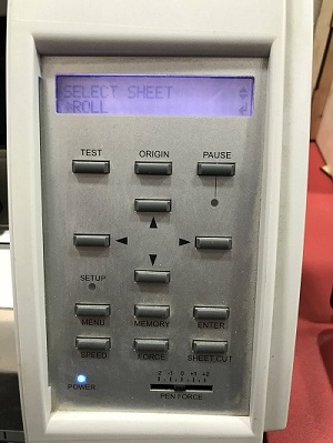
Despite the fact that I had a roll, yet I didn't want the machine to measure its length because it's too long, so I chose the roll option, but I DON'T RECOMMEND YOU TO DO THIS because it's better to know the length and width if you'll make something big for a car for example.
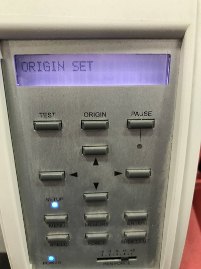
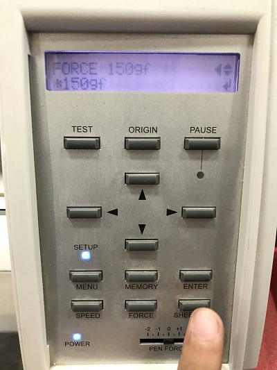
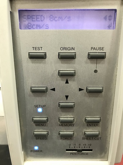
Then you have to test different speeds, and forces and before you start long press the button origin till this screen appears:
I've found that is the optimal speed and force in my black vinyl and using my machine.
Here's the test result:
My design after cutting:
Laser cutting:
I started by designing the hexagon part which I decided to use because of how there's 6 sides in it which will help in making numerous designs with few parts which's ideal for manufacturing any puzzle like kit.
However, before I show you my parts, you need to understand and learn how to make global variables and to make a parametric design, so when you edit one parameter you change the value in the entire design.
Part 1: Hexagon
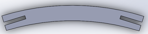
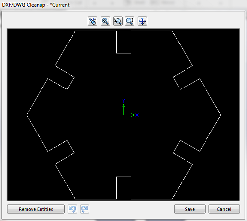
Part 2: Curved part
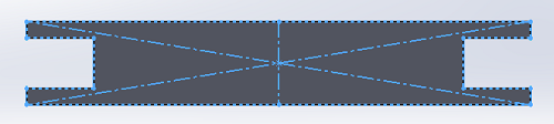
Part 3: Straight part
After Making your 3D parts I export them to dxf to export them to LaserWorks which's the software our machine communicate with.
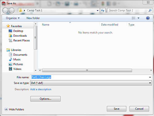
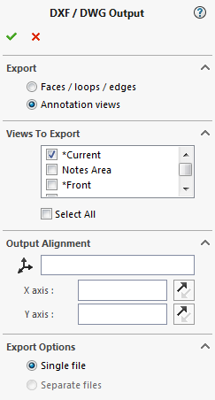
and the last step
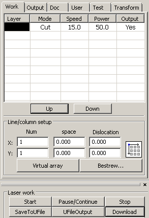
Moreover, this the LaserWorks software and how to import you saved DXF file to it.
Download gives a name for the file on the machine, but the Start option instantly starts the file without downloading the file on the machine.
Here's how to import your DXF design into laserworks and adjust cutting power:
First you have to use the arrows to move the laser position then set the machine's origin by clicking on
then you add your sheet of any material you'll work with (MDF wood for example).
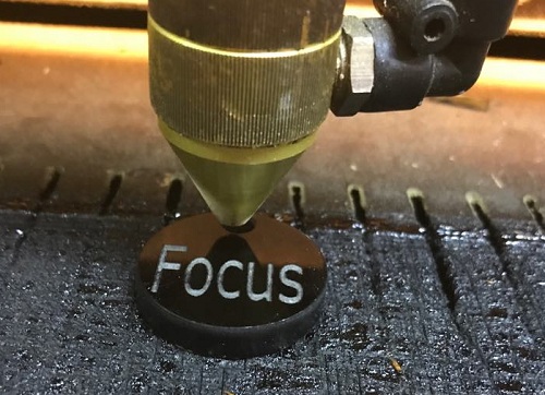
after that you want to make sure that the laser beam will be focused on the surface of your material because:
less focus might not cut properly
more focus might burn the material more than desired and ruin it.
In my machine there's a 6mm width acrylic part made to make sure that
from the top layer of the material to the laser head nozzle is 6mm exactly.
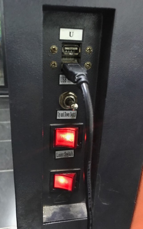
Now you're wondering what to do if found less than than desired or more ??
I have on the right side of the machine a switch that will pushed up the bed rises and when hold down the bed goes down, so by going back and forth you can calibrate you focus based on your machine
After setting the origin you have to do 3 things
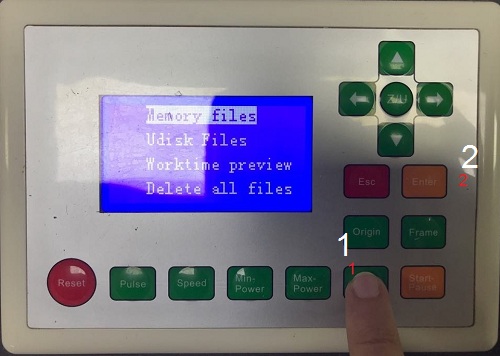
First, you have to ensure that the file fits in the machine area size and whatever the material size you're providing, and here's how:
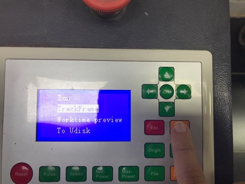
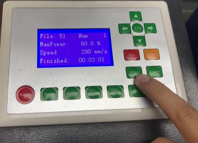
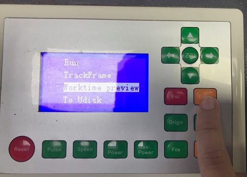
Second, work time preview which gives you how minute your design will take, so you can know how much time your design/kit takes, and here's how:
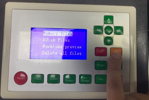
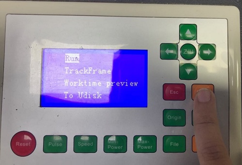
Lastly, to start actually cutting your design, and below shown how:
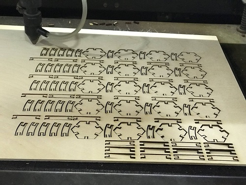
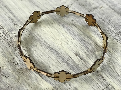
My output and construction:
I made a tiara with it then a mobile holder.
Then I made one of the old fab academy student in the lab wear it and he was astonishingly happy as you can see :D

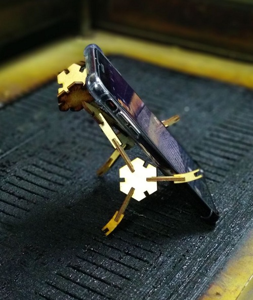
The mobile holder:
My Group assignment contribution:
First, I used my colleague Haithem Abdelkhalek files with minor edits.
The material I tested on was acrylic.
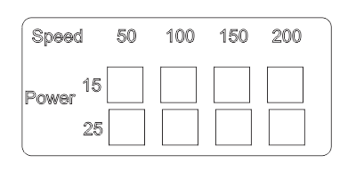
Kerf Testing:
I assigned different values for each square to have different results and figure the optimal value, but to be honest I had already previous knowledge about where almost the range of the acrylic power and speed lie within.
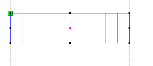
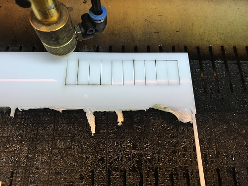
I started by sketching simple rectangles: ( You can do any length you want)
Example:
20mm rectangle cut into 10 smaller rectangles, so each rectangle now is 2mm.
20mm / 10 = 2mm
Note: count by rectangles or inner lines don't count the outer rectangle lines, if you do so the number will always be (n+1).
The photo below is a rectangle cut into 10 rectangles but have 11 side.
After that I cutted them on the laser cutter and grabbed them to the left and measured the empty distance created on the right:
Measuring:
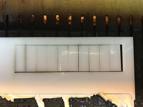
After measuring:

By getting this number and dividing it by 10 you get the kerf equal to 0.2 (1 decimal place).
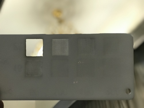
Cutting values and result:
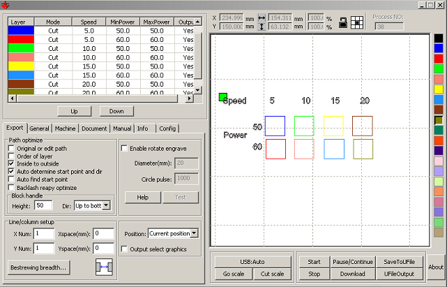
the scanned part values:
result:
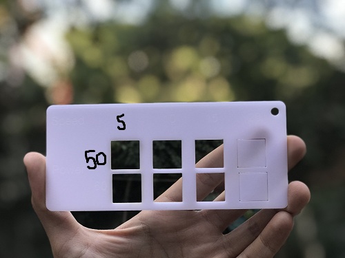
As you can see I did my best to show the values, but still I needed the help of paint and the best value was (Speed 15 & Power 50)
The columns represent 5 10 15 20
The rows represent 50 60
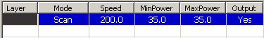
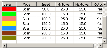
Scanning values and result:
the scanned part values:
and I tried different value that doesn't exist in my test values to make the numbers and letters.
also I managed to use the perfect value used in cutting the previous test in cutting the scanning test values table.
s
The result:
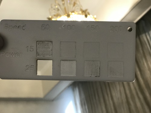
From my opinion the best values are (150 Speed & 15 Power).