01
03
11
week 07 | embedded programming
12
The assignment for this week, was to program a microcontroller. I already made some additions to the hello ftdi board, which was my first time to program a microcontroller by myself, but I wanted to learn to program more models than only AVR. So, I decided to draw a PIC demoboard, as we have the corresponding PICKit3 Programmer in our Lab. (I hope I'll find some time to learn or just play a bit around with STM32, too) This assignment is divided into several parts. First, I wanted to show what I've done with my hello.ftdi board, then I'll show my PICBOY.
13
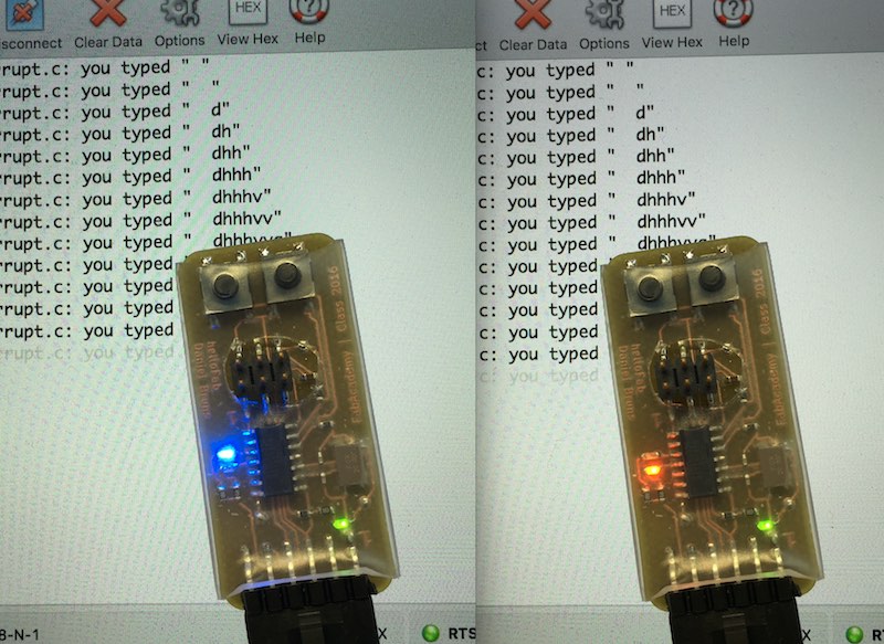
As I was drawing my hello ftdi board, the assignment was to add some LEDs and buttons. I decided to use one of my LEDs as simple state LED, which is on, when the board is powered. I like this simple way to get the first sign of life from my hardware. The two other LEDs change while typing something.
14
15
The modification of the code was nearly simple. I took Neils ready-to-use firmware for the hello.ftdi board and added just some simple lines code. I made these changes in a text editor, and followed Anna's tutorial to program the board via my own FabISP on a nearly virgin Linux VM.
16
To initialize the LEDs and buttons, I had to define and assign the pins, according to the datasheet supplied by the manufacturer.
17
#define led_port PORTA
#define led_direction DDRA
#define led_pin1 (1 << PA2)
#define led_pin2 (1 << PA3)
#define button_pins PINA
#define button_direction DDRA
#define button_port1 (1 << PA7)
#define button_port2 (2 << PB2)
18
The next step was to turn on and toggle the LEDs while typing. To include this routine, I had to do 2 things. First, I included into the interrupt routine a line, which inverts both values from led_pin1 and led_pin2, this results in changing the LED states.
19
				...

			   	 led_port ^= led_pin1|led_pin2;

				...
20
The second step had to be done in the main routine. The first step was to declare the pin direction as output.
The second line sets the led_pin2 as high, so the LED at led_pin2 is off and the LED on led_pin1 is on on startup.
21
				...

				led_direction |= led_pin1|led_pin2;

 			  	led_port |= led_pin2;
22
Then, as I said before - I simply used my VM, followed Annas's tutorial and wrote the firmware into my hello.ftdi board.
23
24
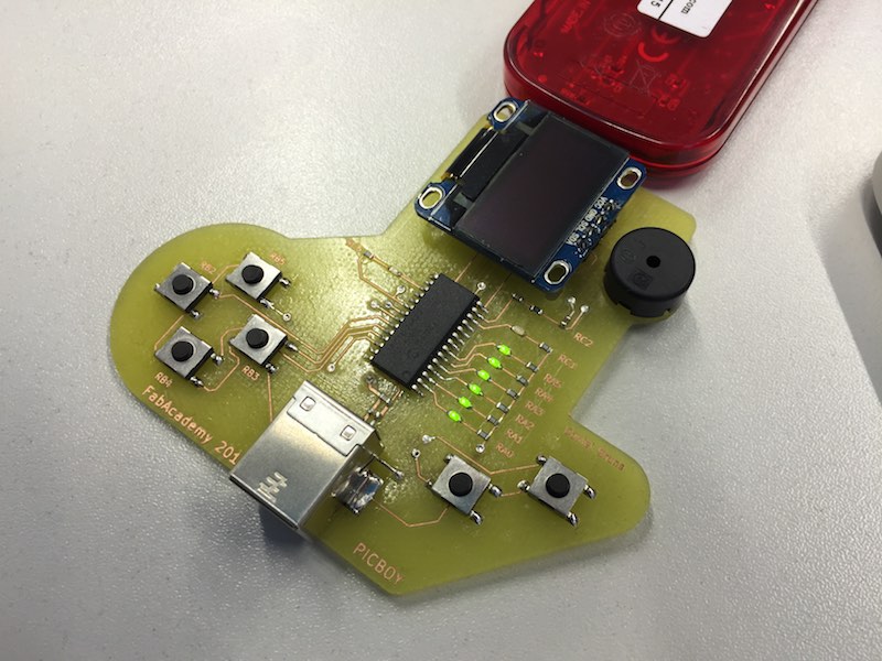
As second part for this assignment, I designed a complete new PCB - my PICBOY. This is a microchip demoboard and thought as Tetris emulator. I hope there is enough time left to port and develop a Tetris to this board.
For the first steps, I simply brought this board to a working state, where the LEDs are blinking. This is the bare minimum due to the fact that the last weeks were full with a lot other organization stuff in my office.
25
26
As microcontroller I chose a PIC18F26K22 for my PICBOY. The other parts are some simple green 0603 LEDs, a buzzer, a 0.96" OLED display and some SMD buttons. The USB connection is thought as power source. There is no data link.
27
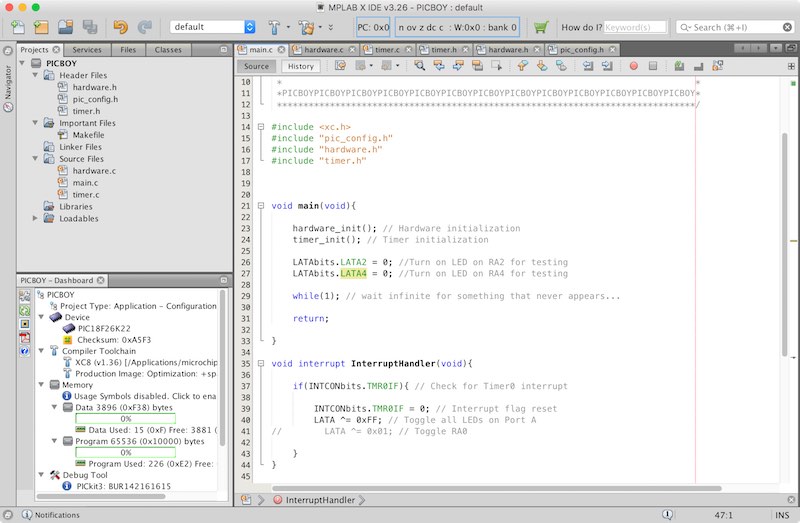
As toolchain, I used the MPLAB X from Microchip with their XC8 compiler. As I mentioned above, I used a Microchip PICKit3 for programming and debugging, which is a very nice extra feature which helps when something doesn't work as it should.
28
Download my KiCad PICBOY design files as .zip (open with Nightly Builds after Sept'16)
29
The first thing when programming a microcontroller, you should open - best option: on a seperate monitor - the datasheet. Here is the link to the PIC18F26K22 datasheet. Due to the little time left, I one made a simple blink programm upon now.
Datasheets:
Electronic datasheets are a weird compilation of errors, missing documentation and non-functional features beside all the good and very helpful documentation. One of the points I learned for the last years, is to read the so called Errata sheets. They could help a lot to find some of the esoteric problems a board can have. As example, the PIC18F26K22 Errata sheet.
The selected PIC18F26K22 is a 8bit microcontroller with a load of several peripherals, like 3 8bit timer, 4 16 bit timer, 2 I2C and SPI modules, 3 PWM modules, 2 UART modules and much more...
In comparison to the Atmel processors I used, the PIC does not need an external oscillator (whether 1% accuracy in stability are enough), as it is equipped with an internal oscillator. This oscillator is nearly free configurable in the frequency. It is even possible to change the system clock frequency while running the PIC, due to energy saving reasons as mobile platform or something else. While working along with the datasheet and the processor, you have to find and then fix your problems. The PIC offers a really neat and affordable solution for debugging, which is called PICKit.
Assigning the Pins while doing the schematics is a really critical moment. The best way to do this, is printing the according page (this time: page 6) of the datasheet. Just mark the right microcontroller with the right package and mark the used pins with their desired functions, to not double-use them. Another typical fail is to assign a pin which does not have the needed functionality.
One of the most underrated information, is the 'package information' part of a datasheet (this time: page 509-533). This section does not only include the package size and pads. There is even a lot of more information about the land pattern, solder mask expansion, needed solder paste layout and even the vias for heat dissipation. After designing 'fabbable' boards, you have to concern yourself a lot with all these guidelines and specifications.
I've used datasheets all the time in the FabAcademy like in the Electronics design, Electronics production, Embedded programming week, Input week, Output week, Networking week and even the Final Project, as they are the guidelines to produce a functional board.
30
One of the first thing you should do - as called fuses in the AVR universe - is to configurate the configuration words. This is the basic hardware control where you for example set the internal oscillator. The MPLAB X gives the option for the newer PICs to configurate the configuration words as full text option - so you only have to look sometimes in the datasheet, when the explanation in the program is not enough. I stored these configuration words in a complete new file, called pic_config.h .
31
Download or watch my configuration file
32
To tell the PIC where the LEDs are attached and which speed it should run, we also need a hardware configuration. I seperated this part into a new file, called hardware.h. In this file I enabled the internal oscillator, set it to 16MHz, and enabled the PLL. The lines below assign and define the I/0 configuration for the LEDs and turn on the PIC internal pull-up resistors.
33
			void hardware_init(void){


   			// First, we'll do the hardware initialization

   			// Internal oscillator configuration to 16MHz

  			OSCTUNEbits.INTSRC = 1; // Select the internal HF oscillator

    		OSCTUNEbits.PLLEN = 1; // Turn PLL on, this means: 4 times more frequency

    		OSCCONbits.IRCF = 7; // Select 16Mhz


    		// I/O configuration

    		LATA = 0xFF; // Port A is used for my LEDs (against +5V), so we set Port A to high (hexwert berechnen um nur die benoetigten Ports anzuschalten...)

    		TRISA = 0x00; // Set them output to use them


    		LATB = 0x00; // Port B is used for the input buttons, so there is no output

    		TRISB = 0x3F; // Set RB0 up to RB5 as input

    		WPUB = 0x3F; // enable the internal pull-up resistors for RB0-5

    		INTCON2bits.RBPU = 0; // Enable the pull-up resistors in general


    		LATC = 0b01000110; // The Buzzer on RC2, and both LEDs on RC1 and RC6 are set to high - due: LEDs are active in low state

    		TRISC = 0x00; // No inputs in Port C

    		}
34
To get the first signs of life, I used Timer0 (see datasheet) to get a steady blinking of my LED. As this timer has two options - count to 255 (which is 8bit) or count to 65535 (16bit), I can use it to divide the clock up to 65535. The PIC is - in my configuration - running at 16 MIPS, so there is a lot of dividing needed to get a slow blinking LED. There the prescaler comes in. It helps us to scale down the signal.
35
The first step is to divide the 16 MIPS with 256 through the prescaler, which gives you 0.0625
36
In the second step, the timer counts with this frequency up to 65535, which gives you nearly 0.95Hz
37
I had to configurate the interrupt as well, as the interrupt is used to reset the timer in the main routine. The interrupt configuration is even done in the configuration file. At this point, I was very proud of the debugging function, as I forgot to set one configuration word which causes that the interrupt does not work. I devided my program as well and seperated these two parts in a new file, called timer.c .
38
	void timer_init(void){

    			// For the first tests, we'll need a Timer, so I decided to use Timer0

    			// This methode is slower instead of using a single hex or binary value to initialize the timer (8 write commands instead of 1, -> 8 times slower)

    			// Here is the configuration...


    			T0CONbits.TMR0ON = 1; // Start timer - at the end.

  			  	T0CONbits.T08BIT = 0; // Set to 16bit mode

  				T0CONbits.T0CS = 0; // internal clock = 16MHz (will be devided through prescaler)

				T0CONbits.T0SE = 0; // does not matter this time

    			T0CONbits.PSA = 0; // Set prescaler on

    			T0CONbits.T0PS = 7; // Set prescaler to 1:256 -> clock input is 62.5kHz


    			// Interrupt initialization

    			INTCONbits.INT0IE = 1; // enable Timer0 interrupt


    			RCONbits.IPEN = 0; // switch off interrupt priorities

    			INTCONbits.GIE = 1; // switch on interrupts

    			INTCONbits.PEIE = 1; // switch on peripheral interrupts

				}
39
Download my timer and interrupt configuration.
40
To get a first sign - I configured two LEDs in the main routine. These LEDs show up, when the interrupt is not reached. Just for me...
41
In my interrupt routine, I'll toggle all LEDs connected to port a, upon the timer resets.
42
43
Download my MPLABX project as zip
44
As you can see, the first startup for a microcontroller is a bit fuzzy, but the program itself is very small. This might be the reason why boards like Arduino etc. are so popular - because their programming environment include a lot of libraries. These libraries and preconfigured boards save a lot time while prototyping or learning, but you'll never learn the whole process which stands behind those programming environments.
45
For example, this is the same program from the Arduino Example library. It does exactly the same...
46
		void setup() {

 		 // initialize digital pin 13 as an output.

 		 pinMode(13, OUTPUT);

		}


		// the loop function runs over and over again forever

		void loop() {

  		digitalWrite(13, HIGH);   // turn the LED on (HIGH is the voltage level)

  		delay(1000);              // wait for a second

  		digitalWrite(13, LOW);    // turn the LED off by making the voltage LOW

  		delay(1000);              // wait for a second

		}

This work by Daniel Bruns is licensed under a Creative Commons Attribution-NonCommercial-ShareAlike 4.0 International License.