01
03
15
16
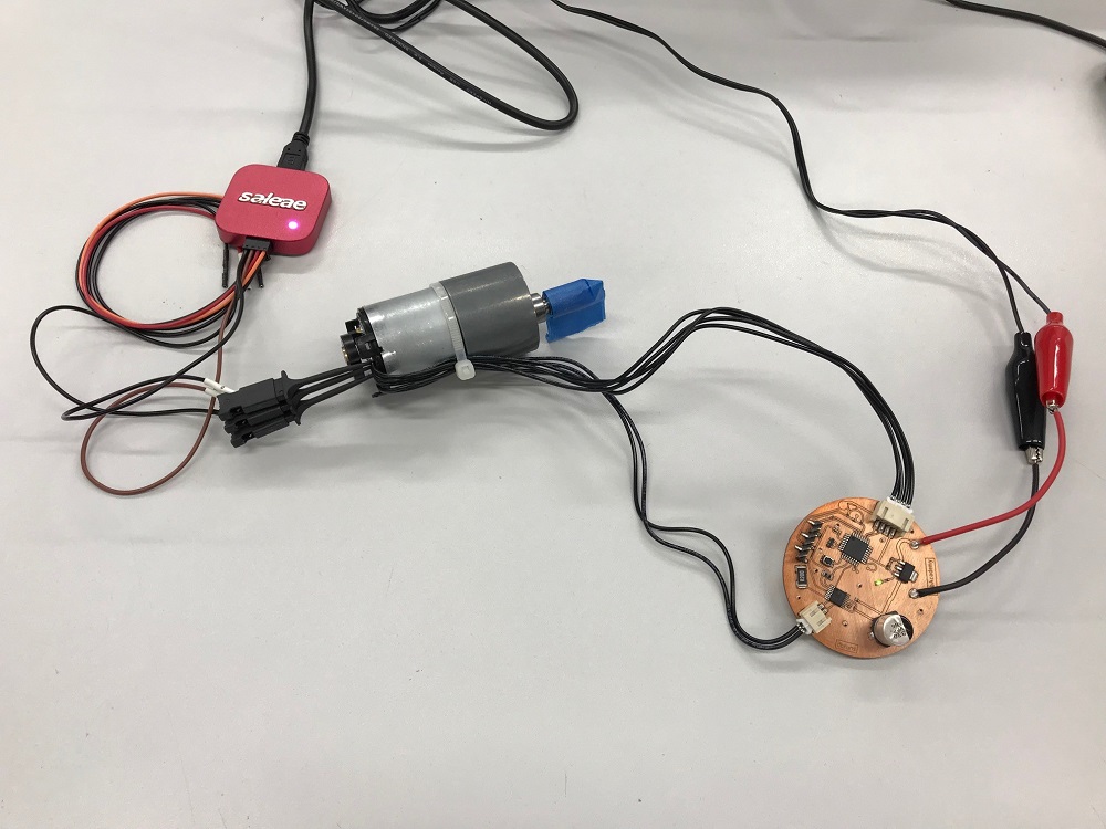
I decided to test a part of my final electronics on a separate board, to fulfill my assignment for this week. The gearmotor is the best noisiest output device, I found. This is the schematic.

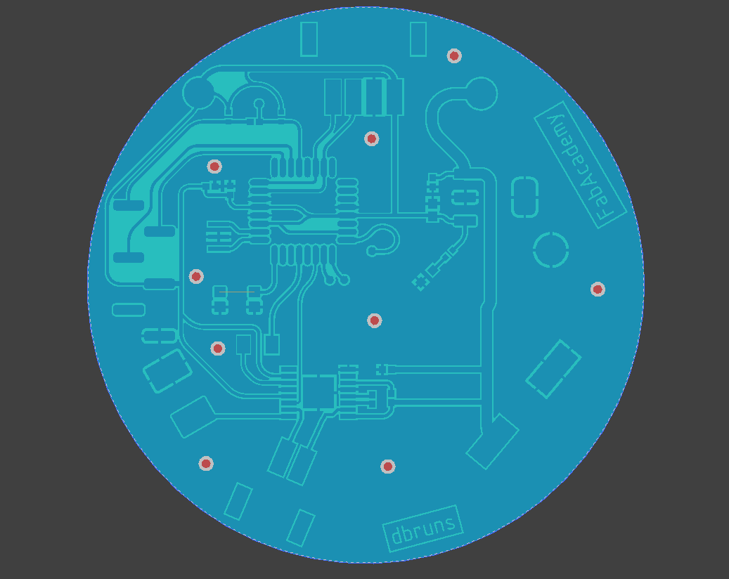
This is the layout of the board. Not that nice, but it works properly and is enough for this test. I needed the header for the FTDI cable to read the encoder count via the serial connection.
This is the finished and assembled board. You'll find the productions files at the end of the page.
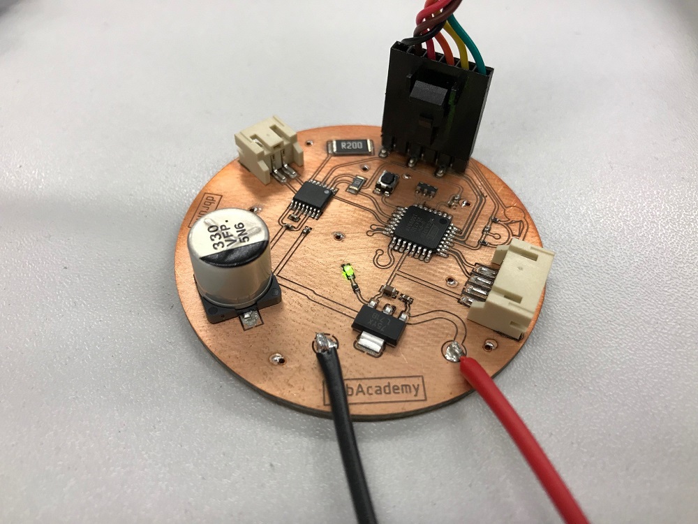
The used gearmotor is a 37D /w 64CPR encoder which is controlled via my DRV8801RTY full H-bridge. Using a H-bridge is a neat and the industrial-like way to control a brushed DC motor efficiently.
17
The encoder is needed for my final project to control the movement of my skaterdolly exactly. The used encoder is an incremental encoder which outputs 2 wave form signals with 90° phase shift. This behaviour allows to measure the speed and even - through the fixed 90° phase-shift - the direction via 2 hall sensors.
The following code is to test the input device and show the results in the serial monitor. The first (not shown) part is the regular declaration, the second is the setup. The third and forth part accelerate and decelerate the motor via PWM, while the serial commands display them in the serial monitor. The seventh and eighth part do the same in the other direction (not shown here). The last is the interrupt, which is initialized in the setup. If the interrupt condition is triggered, the interrupt interrupts the normal program and jumps to the interrupt function. This function analyzes the motor direction and counts the steps.
Microcontroller Interrupt:
The 'Interrupt' is a function to call a pre-defined function or anything else instantly, due to a specific condition. The Interrupt is able to be triggered at any point of the program and bypasses the normal, fixed, program flow. In this case, it is reasonable to use a Edge-triggered interrupt which is triggered by a level-change from low to high or high to low on the assigned pin. This is the documentation to configure an interrupt via Arduino properly. 'Edge-triggered' is the same like 'Change' in the Arduino documentation or 'Interrupt on change' in microcontroller datasheets. It is even possible to configure a trigger event on the interrupt (depending on the microcontroller, as this is - normally - a hardware function) when the level on the pin is 'low' or 'high' or even on 'rising' and 'falling' conditions. The 'change' or edge-triggered mode is combined from 'rising' and 'falling'.
18
Code:
...

void setup() {
  pinMode(EncMA, INPUT);                        //Set Encoder Channel A as input
  pinMode(EncMB, INPUT);                        //Set Encoder Channel B as input
  pinMode(17, INPUT);                           // Pass Through for Interrupt
  pinMode(18, INPUT);                           // Pass Through for Interrupt
  attachInterrupt(1, EncoderEvent, CHANGE);     // initialize interrupt
  pinMode(motor_direction, OUTPUT);             // Set DirectionMOT as output
  pinMode(motor_PWM, OUTPUT);                   // Set PWM_MOT as output
  Serial.begin(9600);
}

void loop() {
   digitalWrite(motor_direction, HIGH);
 while(PWM_speed < 75){                         //Set max. duty cycle / 255 for full speed
  analogWrite(motor_PWM, PWM_speed);
  PWM_speed = PWM_speed + PWM_ontime;
  Serial.print("EncCounts: ");                  // Serial Monitor output
  Serial.println(EncCount);
  Serial.println();
  delay(100);
  }
...
}


void EncoderEvent() {
  if (digitalRead(EncMA) == HIGH) {
    if (digitalRead(EncMB) == LOW) {
      EncCount++;
    } else {
      EncCount--;
    }
  } else {
    if (digitalRead(EncMB) == LOW) {
      EncCount--;
    } else {
      EncCount++;
    }
  }
}
19
To analyze this function, I used my Saleae logic analzyer.
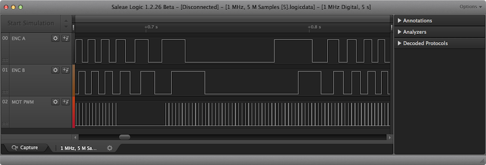
The first pictures shows a slow motor movment (low PWM duty cycle on channel 3!) - this picture is great to see the 90° phase shift of the encoder channel A and B.
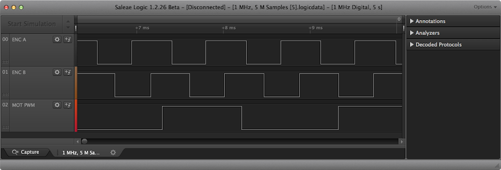
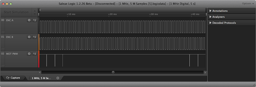
The second images shows the stopped motor (0% PWM duty cycle) and the inertia, which turns the motor a bit longer. When the motor is stopped, the encoder does not provide any signal.
100% PWM duty cycle as example
20
Download the CircuitStudio PCB file
Download the CircuitStudio Schematic file
Download the captured signals as .logigdata

This work by Daniel Bruns is licensed under a Creative Commons Attribution-NonCommercial-ShareAlike 4.0 International License.