01
03
17
18
Let there be noise!
19
I decided to test the H-bridge for my final project PCB on a separate PCB, to fulfill my assignment for this week. The gearmotor is the best noisiest output device, I found. This is the schematic of the separate board:

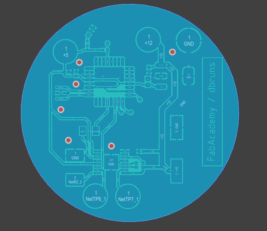
This is the layout of the board, I've made for this week.
This is the assembled PCB.
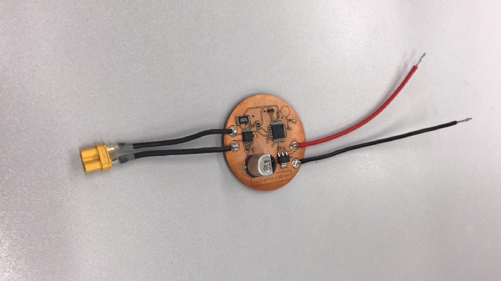
The used gearmotor is a 37D /w 64CPR encoder which is controlled via my DRV8801RTY full H-bridge. Using a H-bridge is a neat and the industrial-like way to control a brushed DC motor efficiently.
20
The code is quite simple. The program initializes the needed pins and accelerates then decelerates the motor via PWM.
Microcontroller Timer:
Microcontroller Timer are a simple hardware-based infrastructure. They are counter, which (normally) count up to 8bit -> 256, 10bit -> 1024, 16bit -> 65536 etc. depending on the their configuration and type. To ensure a stable timing, the timer are based on the system resonators/chrystals clock. As the - in this case 16MHz - frequency is too high, the signal will be reduced to the desired frequency by the internal prescaler, which divides the signal. Even external clock sources via a pin are possible. The Atmel processors are able to generate a PWM signal through the internal compare module and the waveform generator, to output a PWM signal directly on the timer pin. Microchip instead uses a dedicated internal PWM module (which needs a timer).
// Initialize pins
int motor_direction = 8; // motor direction
int motor_PWM = 10; // motor PWM

// Set variables
 int PWM_speed = 0; // PWM speed
 int PWM_ontime = 5; //PWM steps


void setup() {
pinMode(motor_direction, OUTPUT); // Set Pinmode
pinMode(motor_PWM, OUTPUT);
}

void loop() {
 digitalWrite(motor_PWM, HIGH);
 while(PWM_speed < 255){
 analogWrite(motor_PWM, PWM_speed);
  PWM_speed = PWM_speed + PWM_ontime;
  delay(30);
  }
 while(PWM_speed > 0){
  analogWrite(motor_PWM, PWM_speed);
  PWM_speed = PWM_speed - PWM_ontime;
  delay(30);
 }
}
The test setup contains of my Picoscope 3205D and a simple 12V power supply, connected to the PCB. The Picoscope and the corresponding software are convenient tools for recording such tests.
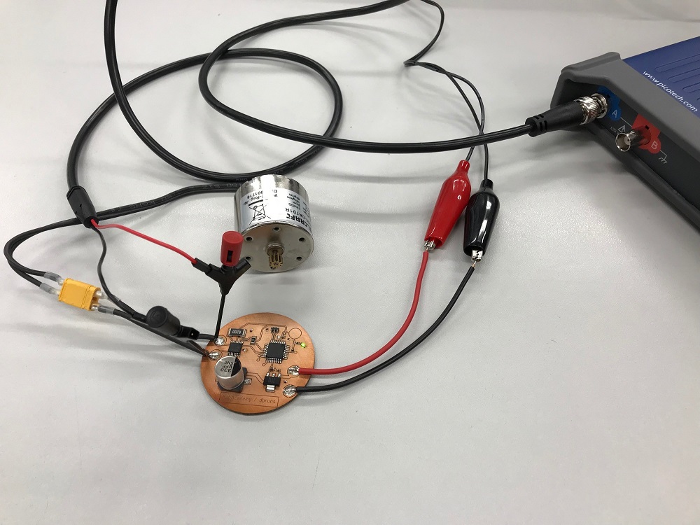
21
I connected my PicoScope to the motor PWM channel, to check if the PWM works correctly. The duty cycle ranges between 0% and 100%, which the motor proportional interprets as voltage between 0V and 12V.
This looks quite nice...

22
Download the CircuitStudio PCB file
Download the CircuitStudio Schematic file
Download my PWM test program as .ino
Download my PWM test program as .txt

This work by Daniel Bruns is licensed under a Creative Commons Attribution-NonCommercial-ShareAlike 4.0 International License.