01
03
19
week 15 | networking and communications
20
This week we had to establish a connection between at least two processors.
To test if my design and code works, I made a very simple PCB, which is capable to communicate with a clone of itself via UART.
The PCB itself is very simple. I used a small PIC18 as processor. One LED (D1) which indicates if the board is powered. The second LED (D2) is assigned to the RC5 pin. The button (SW1) is used as simple input device. When you push the button on one board at least one second, the LED (D2) will flash on the other board when releasing the button, which is connected via UART (see pins 10 and 11 - TX and RX).
BOM (per Board):
1 PIC18F13K22-I/SO 52R6180 Newark
1 0603 LED, blue - in stock before
1 0603 LED, green - in stock before
1 EVP-AA202K 83T2735 Newark
2 0402 470R Resistor - in stock before
1 0402 0.1µF Capacitor - in stock before
1 0.1" Pinheader 1x6 - in stock before
1 0.1" Pinheader 1x4 - in stock before
21
As this board should be a simple example to check if the UART connection works, I made it with simple 0.1" pin header. The 4pin header is for the UART to the other board. The 6pin header is the ICSP header to program the PIC.
I made the boards in KiCad. There is nothing special about it. Just a processor and some small parts. If you're interested in more information, try my KiCad tutorial.
The schematic shows the really simple circuit, as this board is used to just do this (and the group assignment...) only.

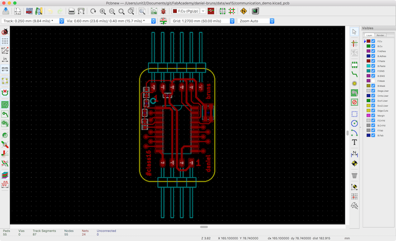
This is the PCB layout I made. Just 2 headers, 1 microcontroller, 1 switch, 2 LEDs and 2 resistors...
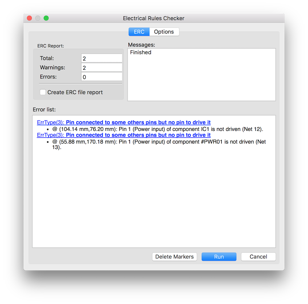
To see if everything is ok, I made an ERC in KiCad. The power pin warning is ok, as the PCB is powered external.
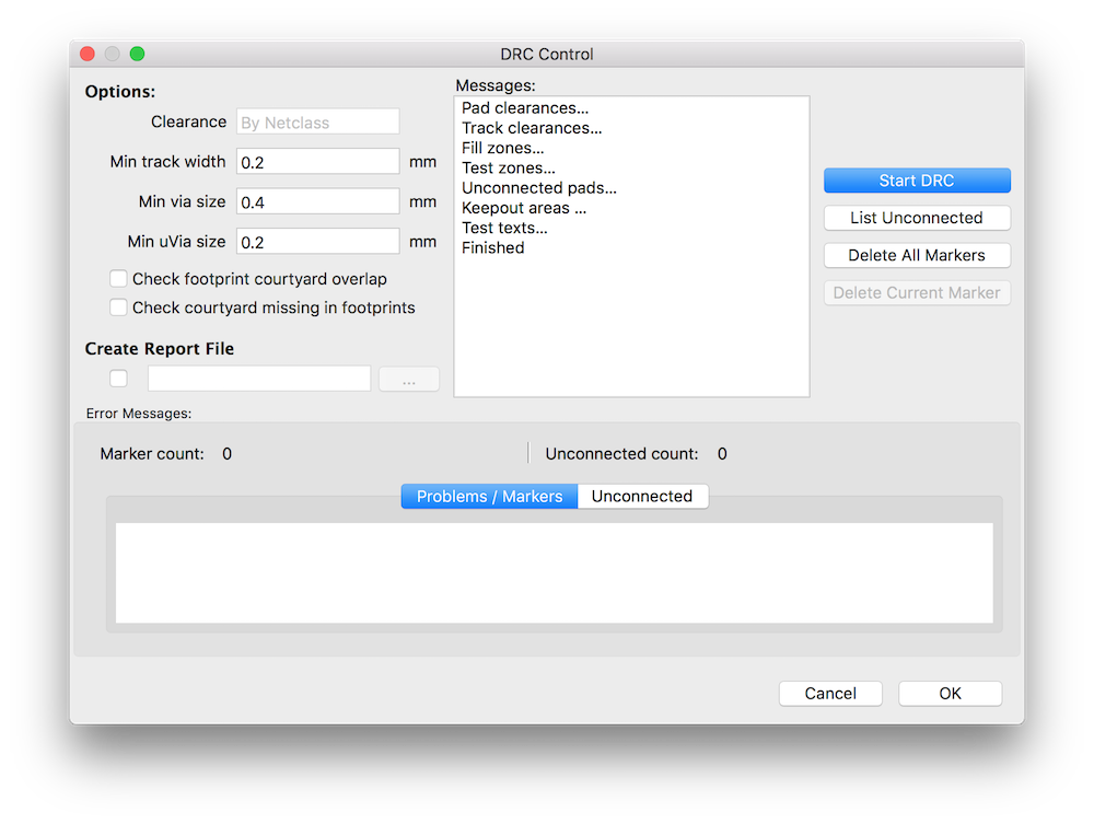
The DRC finished without any warnings or errors. :)
22
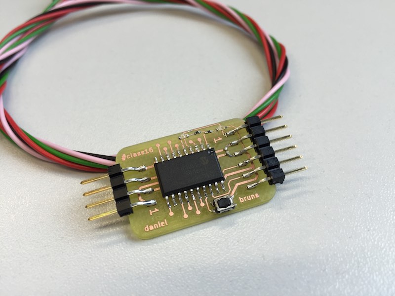
After milling the PCB on the LPKF mill, I soldered all parts by hand - two times.
23
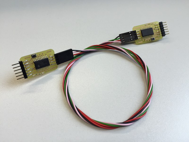
To include the "two processor" factor of this assignment, I made a cable which is between both milled PCBs. As you can see, both boards are completely identical. The cable is the 3.3V power supply for the second board, also.
24
The best way to get all needed information to program the UART, just use the datasheet, supplied by Microchip.
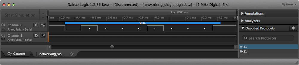
The communication between these 2 boards is realized through UART. Both boards got an ID (1 and 3) and just send an command. If they receive an command for another address, they forward it. The command consists of the board ID and the command number.
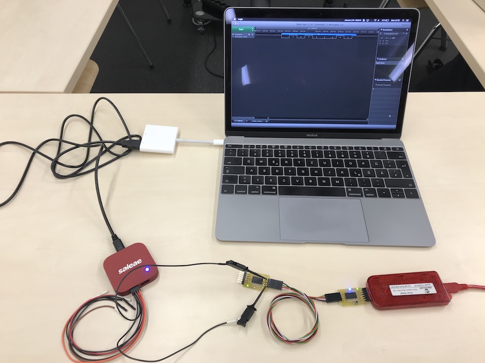
To show how (and whether) it works, I connected my logic analyzer to the network and let it listen to the commands. The logic supports protocol decoding, which is a nice feature to see the plaintext commands.
This is a picture, where the board with the ID "3" sends the command "1" (turn on or off the LED) to board "1".
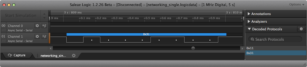
In this picture, the board with the ID "3" receives (the channel is connected to the RX pin) the command "1" from board "1".
This video is our group assignment video I made with Christoph. It shows the adressing much better than just my PCBs connected to each other.
25
Downloads:
My KiCad design files (open with Nightly Builds after Sept'16)
MPLABX project
Logic analyzer data .logicdata

This work by Daniel Bruns is licensed under a Creative Commons Attribution-NonCommercial-ShareAlike 4.0 International License.