Mechanical Design
Random Dutch lunch generator
The machine will help you decide the topping on your sandwich, randomly, and in combinations that you might otherwise wouldn’t have thought of. The bread piece will be placed in a lunchbox that is already standing under the different toppings. Exactly how the random generator will start is not decided yet, but the idea is that a motor will act accordingly to code that is randomizing the different sections of the stage and then opening up the respective funnel that is stopping the topping from coming out.
We decided to divide the work between us; Johanna was going to build the stage, Jelka the construction over the stage, the housing, holding up the topping funnels, Henk would create a construction that could turn tubes so that we could have some tube toppings as well, and Hanna would create the construction for the topping funnels and their respective motor.
Creating the stage and the overall construction
Before starting designing the stage, Johanna had a look at some of the previous student’s work. Emma had also shown us a modular system for stages. However, we decided fairly early that we wanted to work with MDF, and the folding versions of stages would only work with cardboard. As a reference we used the files of the machine that Fab Lab Facens made in 2017. They had made a design in MDF that looked similar to what we wanted to do. They also had a downloadable version of their design. It included the drawings for the x-axis module we wanted to use.
Johanna downloaded the file and started making some changes in Illustrator. The team had decided on some measurements for the machine, and for some reason, she must have gotten them really wrong. However, we didn’t notice this until much later when the stage was cut and assembled. Which resulted in Hanna and Jelka re-doing the design when Johanna was away in Stockholm. We still love Johanna anyway. Blessing in disguise, she got to help when she got back since the file had minor mistakes and we also decided to make a few tweaks to it.
To walk through the processes of re-designing and cutting the stages
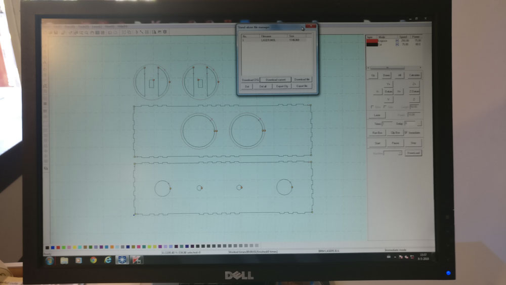
- Johanna exported the dxf file.
- Her Fusion 360 was not happy with her at that moment, and decided to be slow and shut itself off. For that reason, she decided to make the alterations in Illustrator.
- The design was for 6mm MDF, and we were going to use 3mm, hence she had to change all the slots.
- Before changing them all, we did a kerf test. We made three different material thickness; 3mm, 3,2mm, and 3,5mm. All of them had the same slot width hench good press-fit, but the slots with the material thickness of 3,2mm looked the best.
- She changed the slot depth, the material thickness, on all slots and changed the size of the holes. I also took away parts that we were not going to use. This took longer than expected since Johanna had to do every single piece.
- When the design was done, Johanna changed the stroke size to 0,1 and saved the file as an Illustrator CS6 file.
- Johanna uploaded it to the laser cutting software and made sure everything was correct.
- Johanna placed the material on the bed and made a test run for the design. It all looked good.
- She used the settings Power: 45 and Speed: 100 for the cutting.
- Then she pressed start and the cutting went well.
- She assembled the parts and noticed a mistake. The green parts in the picture weren’t cut off. She decided to wait with fixing that, and maybe even do it by hand. This wasn’t necessary since we re-did the whole design.
- Then we noticed that the design was too big. Actually twice, which resulted in Hanna redoing the drawing
In green the design mistake.
First cut of the stage. It is too big.
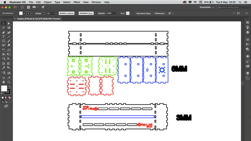
The original file in Illustrator
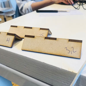
The slot test
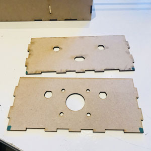
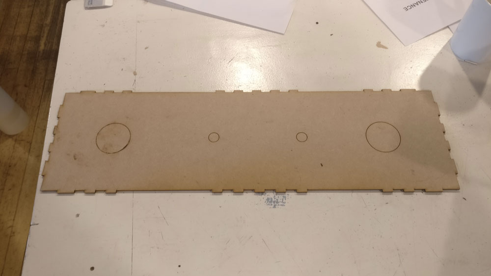
The wrong holes for linear bearing
Attached
In place
Glued to stay in place
Assembled-ish
Jelka’s drawing of parts of the stage
As a reference we used the files of the machine that Fab Lab Facens made in 2017.
It included the drawings for the x-axis module we wanted to use. Johanna ran a test with different slot measurements with the laser cutter.
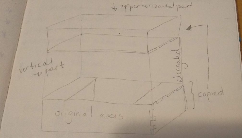
When Hanna had arranged the dimensions we wanted, Jelka used the file to draw the vertical parts and the upper horizontal part that holds the topping-dispensers.
To draw the vertical parts of the stage Jelka used original side panels and elongated them.
To draw the upper horizontal part she copied the lower horizontal parts and drew the holes in that Hanna and Henk needed for their topping dispensers.
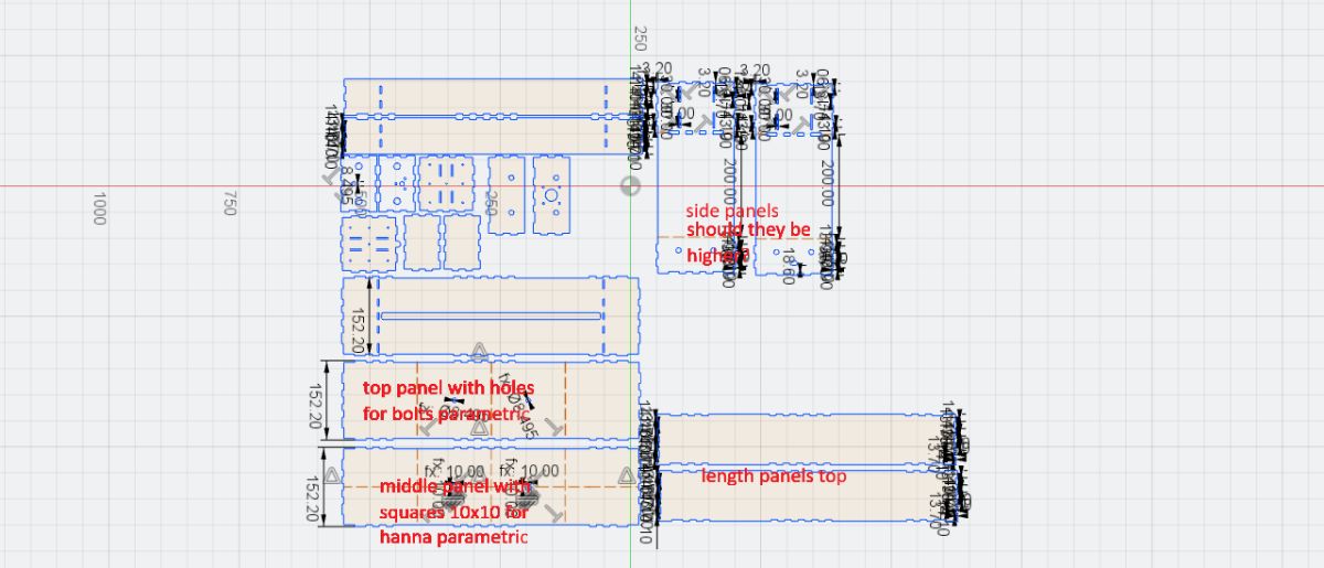
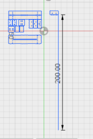
When Jelka was drawing, we communicated via Slack. In the picture below you can see what is what.
The parts that have comments on them in red are the ones she drew.
The are pictures of communicating with the team. With the first picture Jelka asked Hanna if her file was in cm’s.
With the second picture on Slack she asked my team: Are we okay with this height vs length? And the third picture was to ask Henk the distance between the slots.
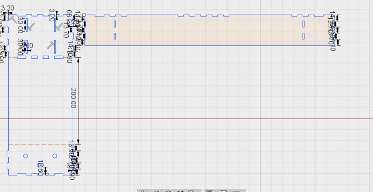
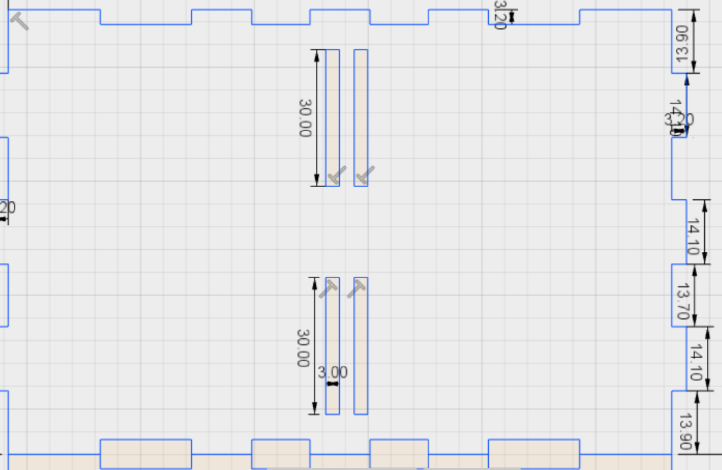
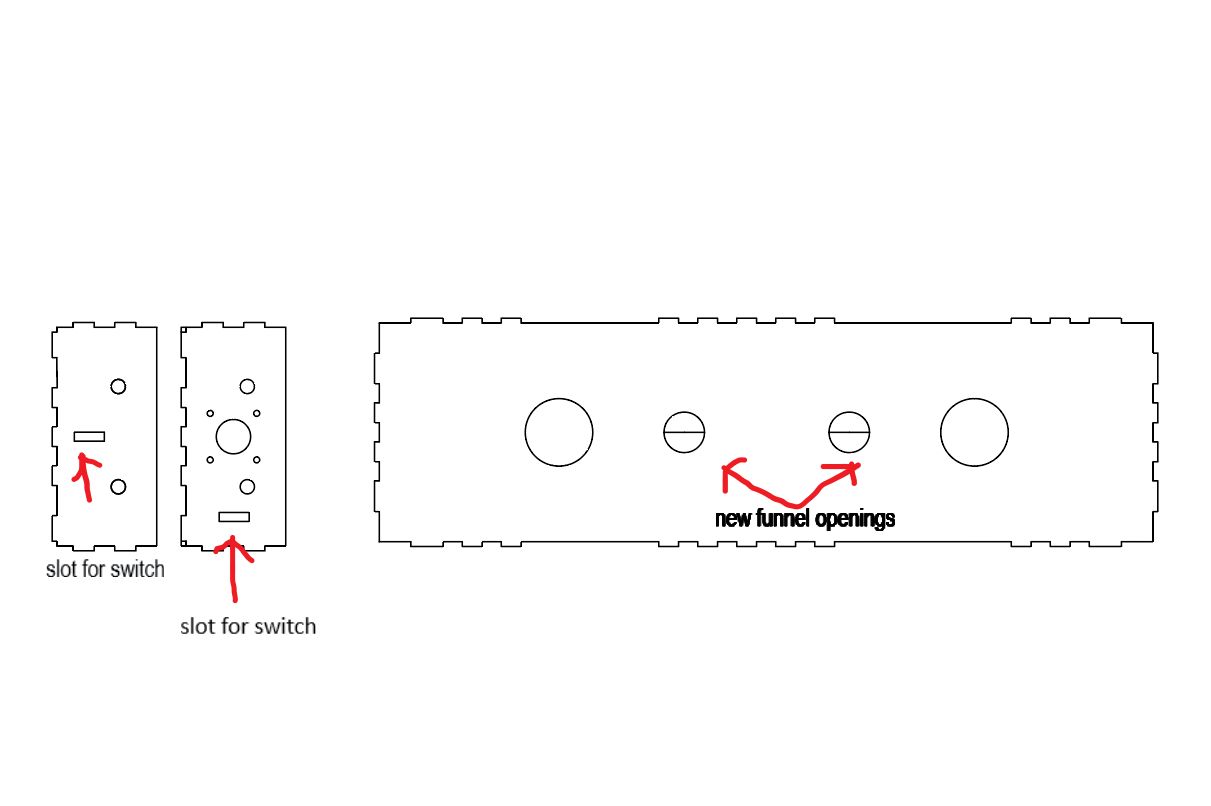
At the beginning of week 16: Machine Design, we realized we needed two switches on each side of the X-arm, so we would have a stop signal for the motor to not turn further after that point and make the sandwich bump into the stage.
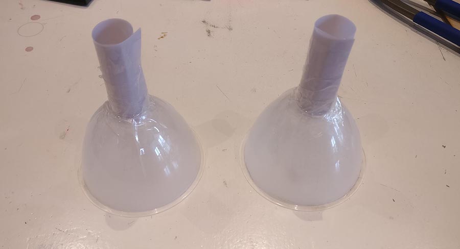
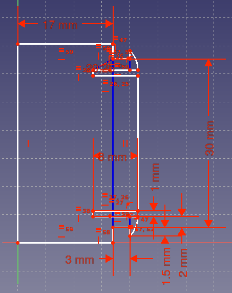
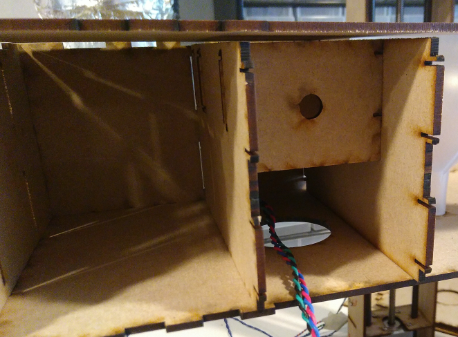
Jelka made two slots for the switches in Fusion. Also we discovered that the holes in the funnels where to narrow for the sprinkles to go through. Hanna cut the funnels and attached plastic to it that she turned into a tube.
Jelka redrew the middle pannel so that these new tubes could go through. Cutting the holes for the tubes diametrici at the same time gives you two half circles that Hanna can use as parts for the opening and closing of the funnels.
The switches have a width of 6mm and a length of 20 mm. she drew exactly these dimensions, but ended up sand papering a little so that the switches could fit in.
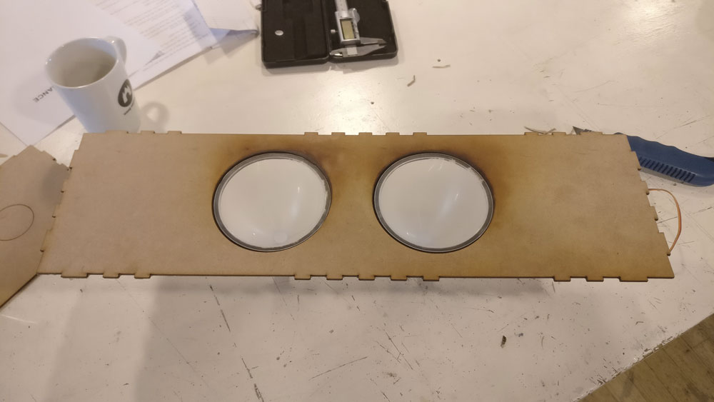
The funnels
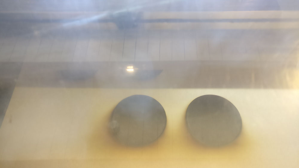
The funnel holes being cut and engraved
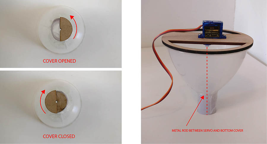
Hanna designed the funnels. They have to be able to open and and close to let the hagelslag out. Also the need to be fixed somehow in the upper part of the machine. She wanted the funnels and the closable lid to nicely sink in the MDF, so she engraved both the edges half way. Unfortunately this left a really thin edge of MDF for lids, so she left that at 3mm. The picture below shows the settings for cutting and engraving the funnel holes and the lids.
Cut settings: speed 75 and power 80; Engrave settings: speed 250 and power 75
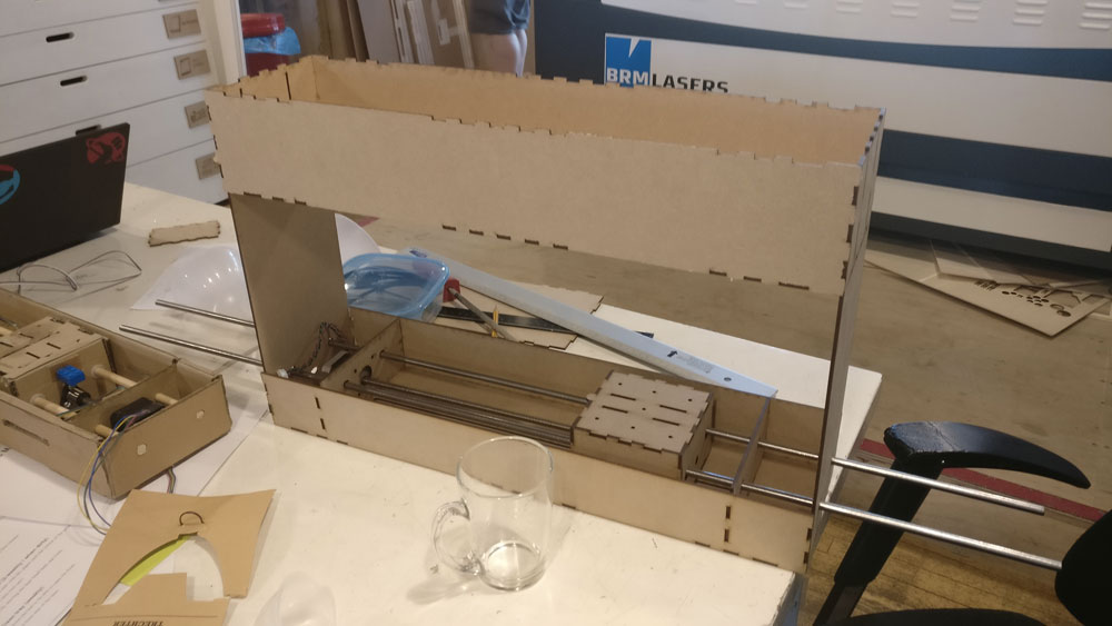
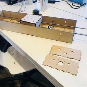
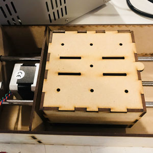
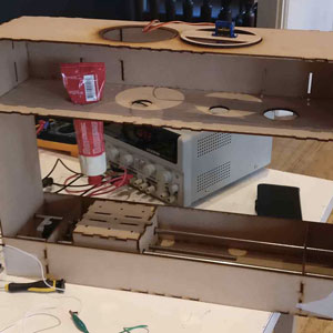
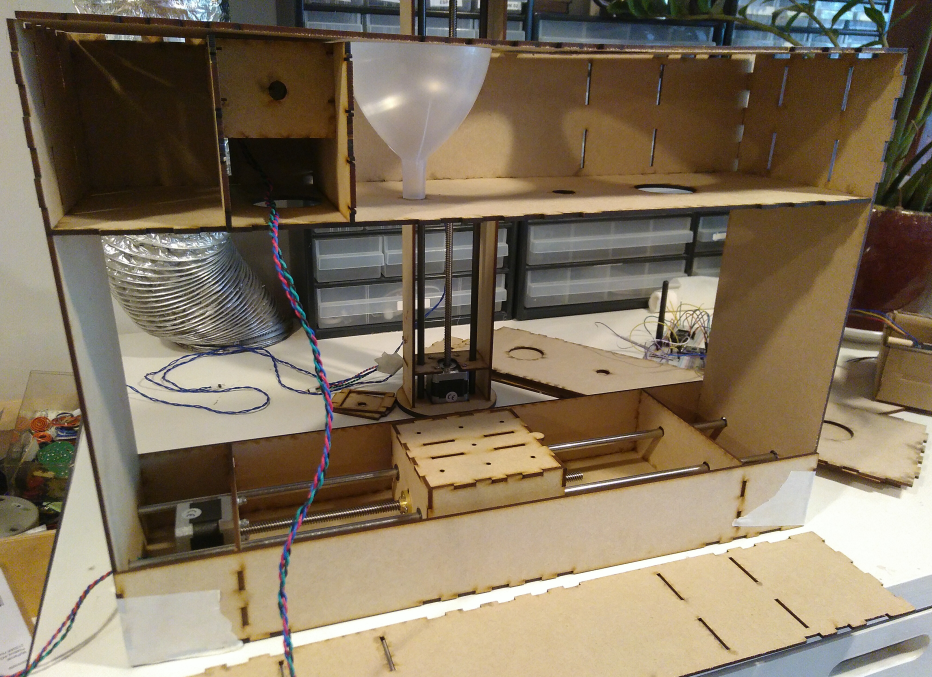
The machine Assembledmbled but not finally
Oh no, it didn’t cut through, changed the cut settings to speed 45 and power 100
The funnels Attached
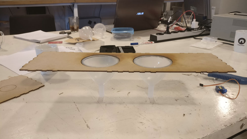
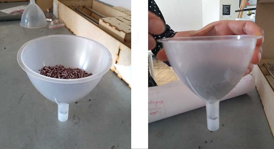
However, when we tested the funnels with chocolate sprinkles we discovered that the funnel opening was too narrow and the sprinkles got clogged. Hanna fixed this by cutting away the bottom part of the funnel and attaching a wider tube to it.
Hanna also designed a system for opening and closing the funnels with servo motors to control the amount and timing of the food deposition. Below is the photo showing the mechanism. The cover closing the funnel is attached with a metal rod to the motor.
tube extractor
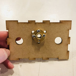
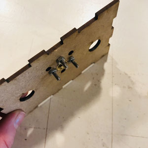
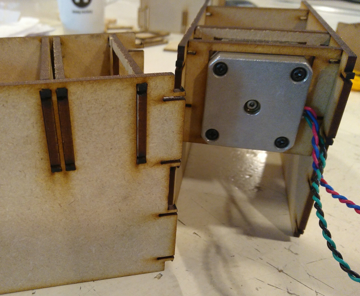
For our machine Henk designed the tube extractor.
Things Henk wanted to learn this week:
- how to make a presfit with joints
- how to design and redesign fast
At the end he should have a tube extractor for our machine. And because images say more than words, and because of fun, he will show the final result:
So as you can see, a tube extractor extracts in this case ketchup out of a tube. It’s done by using a steppermotor. The motor rotates half a revolution and so extruding the ketchup out of the tube.
The motor is in a housing Henk will design this week.
workflow
He did the main design in inkscape. The pressfit with joint he made in freecad, because it was the most complex part, that he also wanted to make parametric.
After making the part fully constrained, he had problems exporting it to dxf. The part came out as a flat line. So after some guessing, he figured out it had to do with the orientation of the plane used in freecad. So he had to change planes. It took him a while to figure out where to do it in freecad. It finally found it under parts design menu.
The file was exported to dxf and then imported in inkscape. Inkscape however give an error when importing dxf files from freecad.
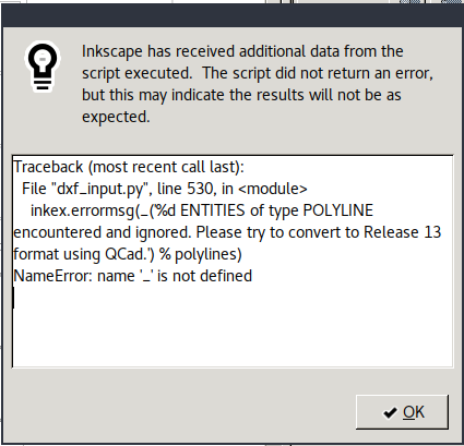
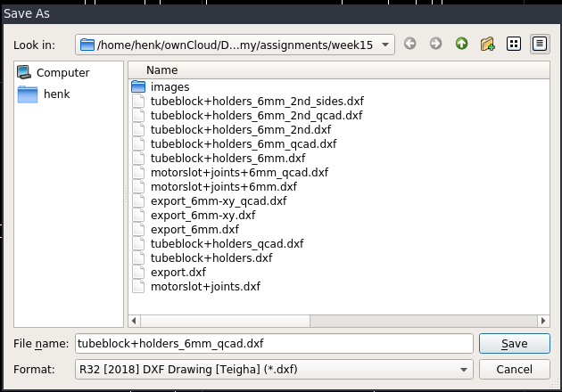
So again he used qcad to open the dxf and save it in another dxf format.
Not listening to errors (who needs them anyway!) he saved the design in DXF R32 format. That on imported fine to inkscape.
The result
Here is the design he made:
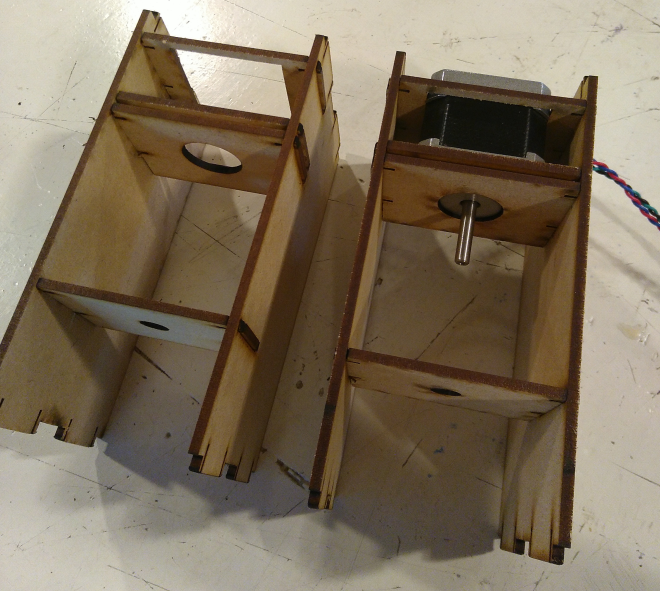
how it looks in our machine
Lessons learned:
- Working fast and exact measurements and placements are not a good combination
- When you have a design in mind it makes sense to think what tools to use. In this case parametric design for the joints in freecad and the final design in inkscape worked really well.
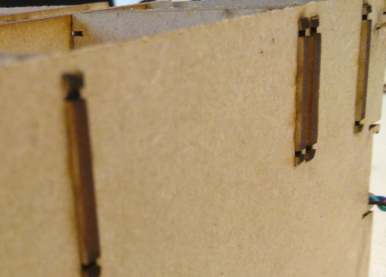
- Joints work really well but they have to be strong enough. He first made joints of 1mm thickness but they broke of course.