Input devices
Introduction
This weeks assignment requires us to design a microcontroller boards and add a sensor to it and read it. As a Group assignment we were asked to measure the bit timing from an input device and measure the power consumption of an output device.
Since this assignment is actually based on previously acquired skills, I will not go deeply into details of designing, milling and soldering, since they are documented already in Electronics Design and Electronics Production assignments.
Board Design
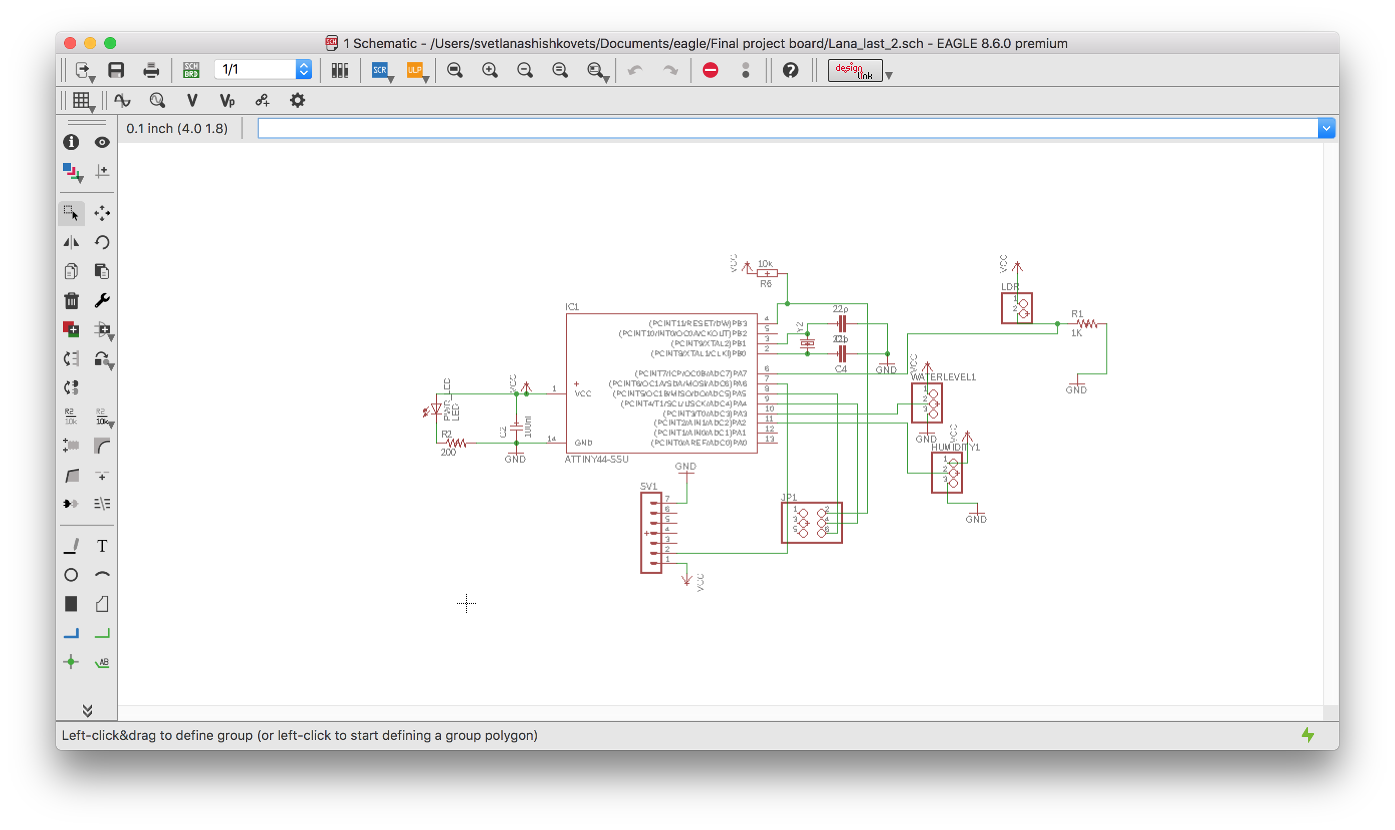
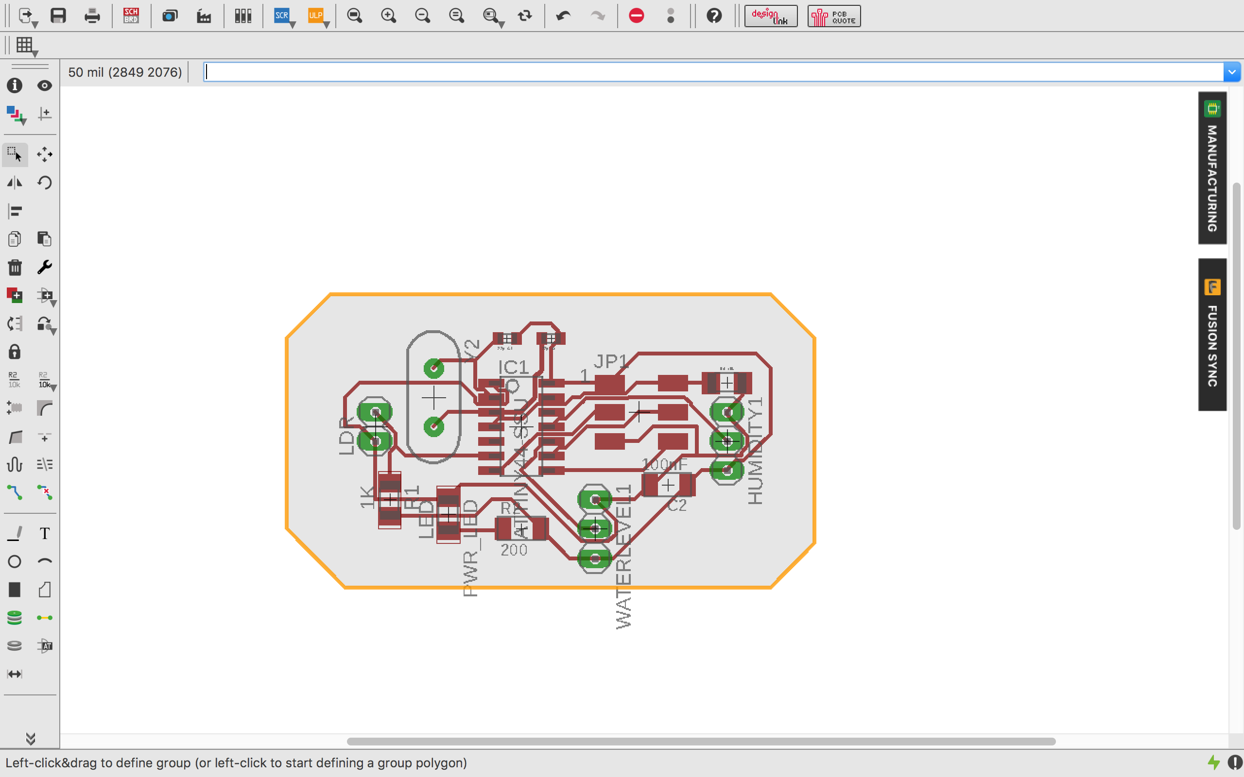
This board was made for getting information from all the sensors I plan to use for my Final project. These sensors are: water level, humidity and light sensor. I started my schematic in eagle by adding all components needed:
- [Microcontroller] ATtiny 44
- [Other] Non SMD photo resistor. This sensor can be used to measure the amount of light it is exposed to, in darker surroundings it will provide a higher resistance while the it will drop in lighter circumstances. More Info.
- [Other] Pinheads
- [2x3] Programming the ATtiny using the VCC, RESET, MOSI, MISO, SCK & GND pins.
- 2 [1x3] Pinheaders just in case for more sensors
- [1x2] Pinheader for the Non SMD photo resistor
- [Other]200Ω Resistor - Protects the LED from too much current
- [Other]200Ω Resistor - Protects the LED from too much current
- [Other] Crystal for measuring time including 2 capacitors. This setup is actually called an oscillator circuit.
- [Other] Resistor for the RESET pin on the ATTINY44.
- [Other] 10kΩ Resistor - Protects the photo resistor from too much current.
- [Other] 10µF Capasitors between ground and power for smoothing the current and keeping the voltage more constant.
That is how my Eagle schematic and board looks like:
Before programing
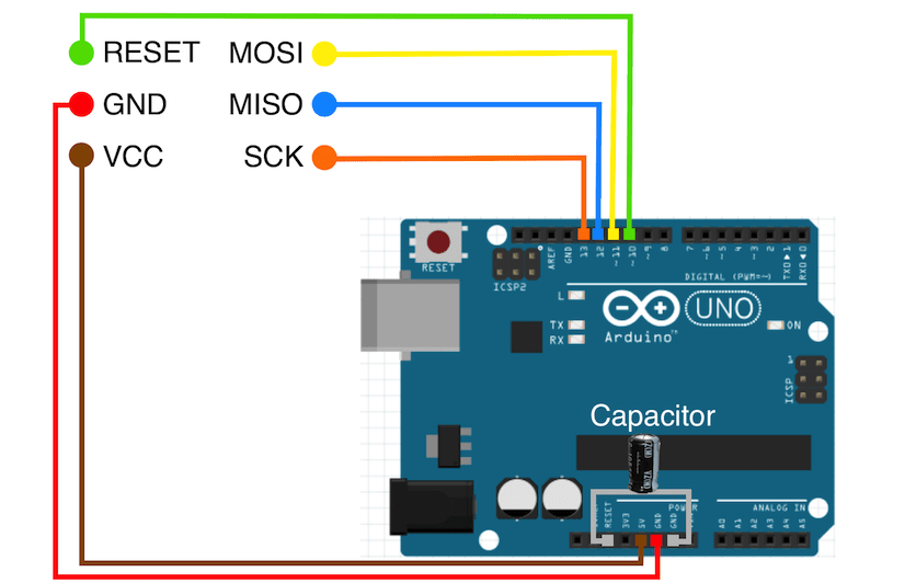
As I mentioned before, I decided to use Arduino as ISP, which I described in the week when we were building the FabISP. Once again, don't connect the board you want to program before running "Arduino as ISP". The next step was to run a bootloader on it. For that you need to connect the board you want to program to an Arduino. That is how you do it:
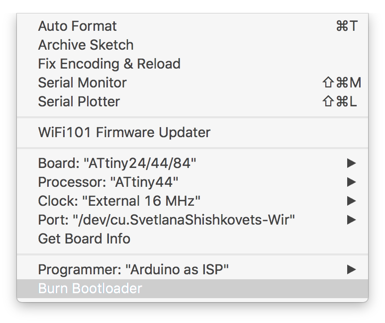
After double checking that all the files are connected, Arduino IDE go to Tools and check that all the settings are defined correctly(in my case it was : BOARD and PROCESSOR - ATtiny44, CLOCK - External 16 MHz, PROGRAMMER - Arduino as an ISP). Than burn bootloader.
And I see Done Uploading! Good sign, now our board are ready for programming.
Programming
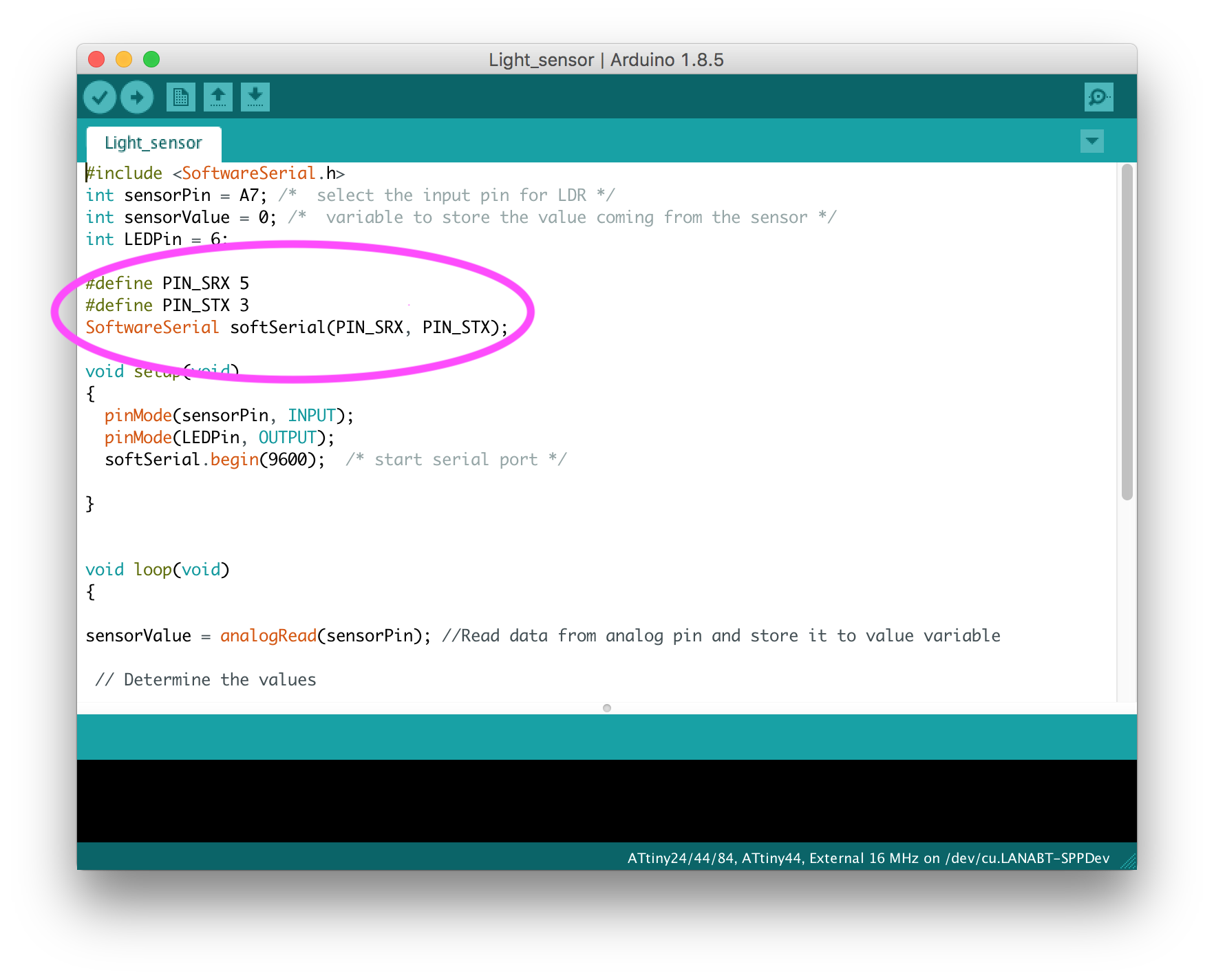
One problem at the very begining of the programming was that the ATtiny44 on the board does not provide a native serial connection so I used the softwareserial library to add this functionality via code. I was really lucky that I had two extra pins just in case or for more sensors. The setup was easy, since I just had to provide tha two pins on the ATtiny for RX and TX and announce them to the softwareserial library(as you can see in the code below). All the Arduino code can be found at the very end of this documentation.
P.S. Now that I know that for serial communication we need RX/TX pins, for my final project board I would rather use another Microcontroller, like ATmega 328, that has more pins and provides serial connection by RX/TX.
Light sensor scaling
LDR is a passive electronic component, it is a resistor which has a resistance that varies depending of the light intensity. The resistance is very high in darkness, almost high as 1MΩ but when the light is very bright.
The LDR gives out an analog voltage when connected to Vcc (5V), which varies in magnitude in direct proportion to the input light intensity on it. That is, the greater the intensity of light, the greater the corresponding voltage from the LDR will be. Since the LDR gives out an analog voltage, it is connected to the analog input pin on the Arduino. The Arduino, with its built-in ADC (Analog to Digital Converter), then converts the analog voltage (from 0-5V) into a digital value in the range of (0-1023).
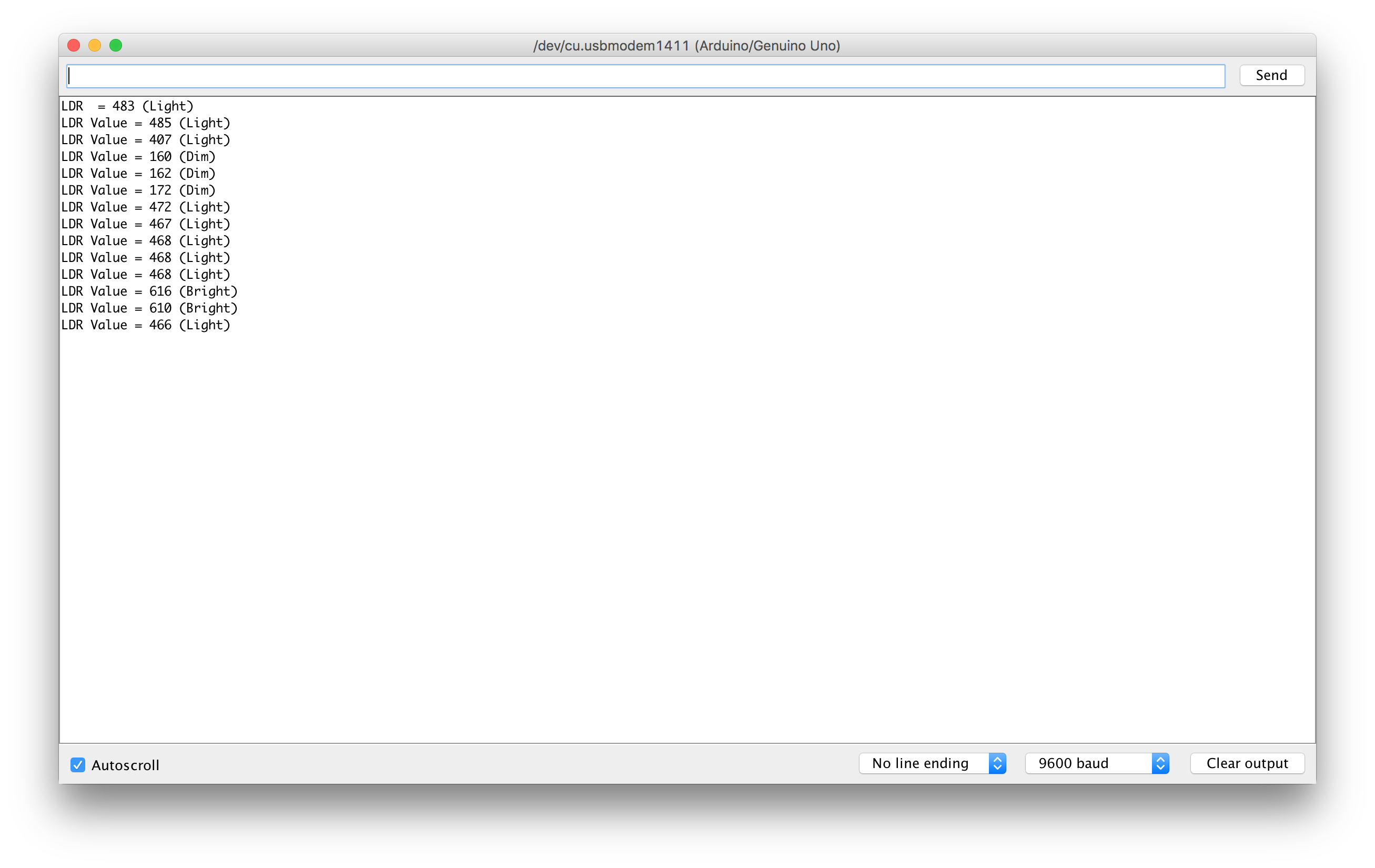
I decided to scale the sensors by the input it gives to the Arduino. So I divided the brightness to the 5 categories(by the input):
- Dark - <100
- Dim - <200
- Light - <500
- Bright - <800
- Very bright - >800
Then I rewrote my program, so the output would be not just numbers, but also the type of light:
Water level sensor scaling
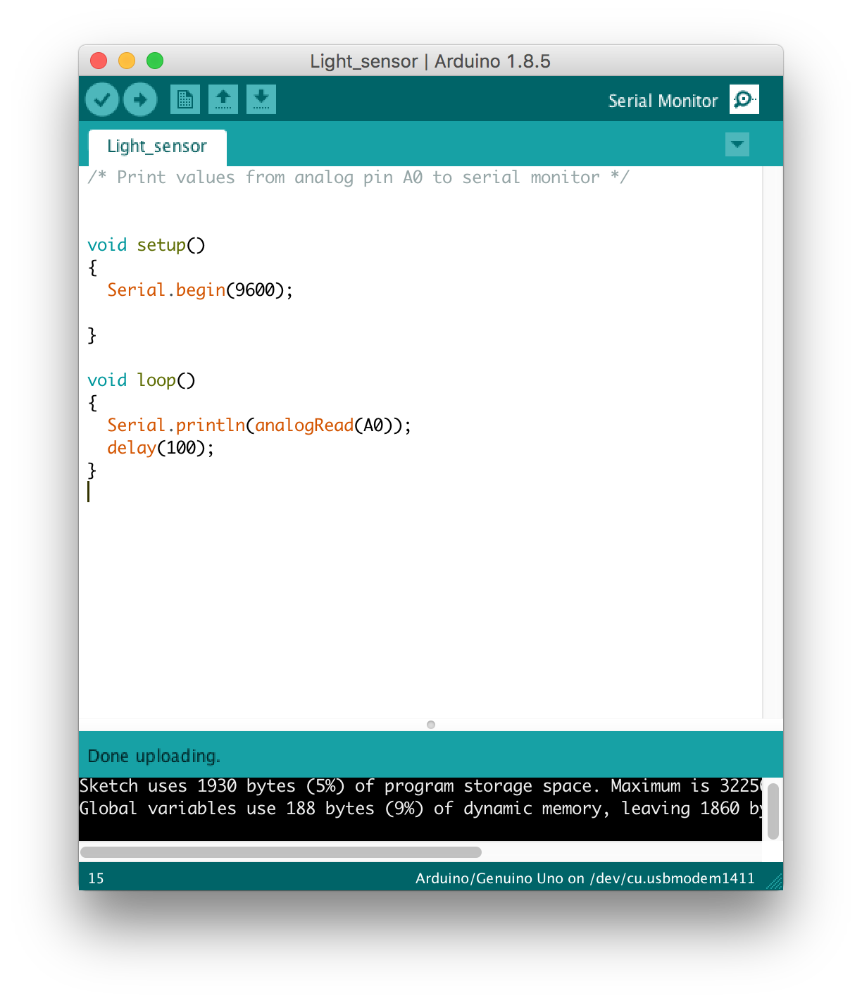
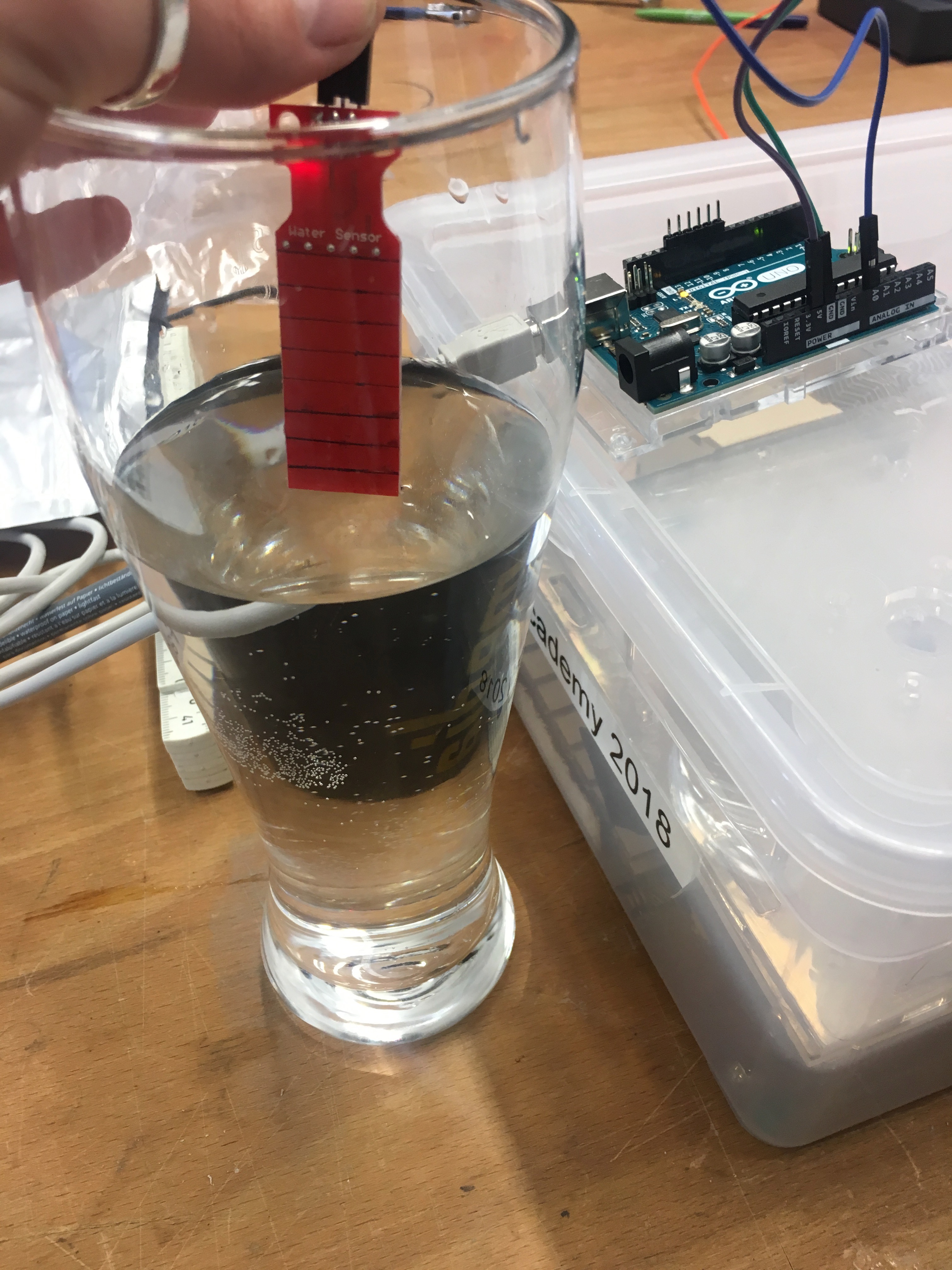
In my final project I plan to use water level sensor. I am not sure yet, if I am going to use self-made one, but since we had one in the FabLab, I decided to test it as well.For that I connected the water sensor to the Arduino and used the simple ARDUINO code to read the sensor signal:
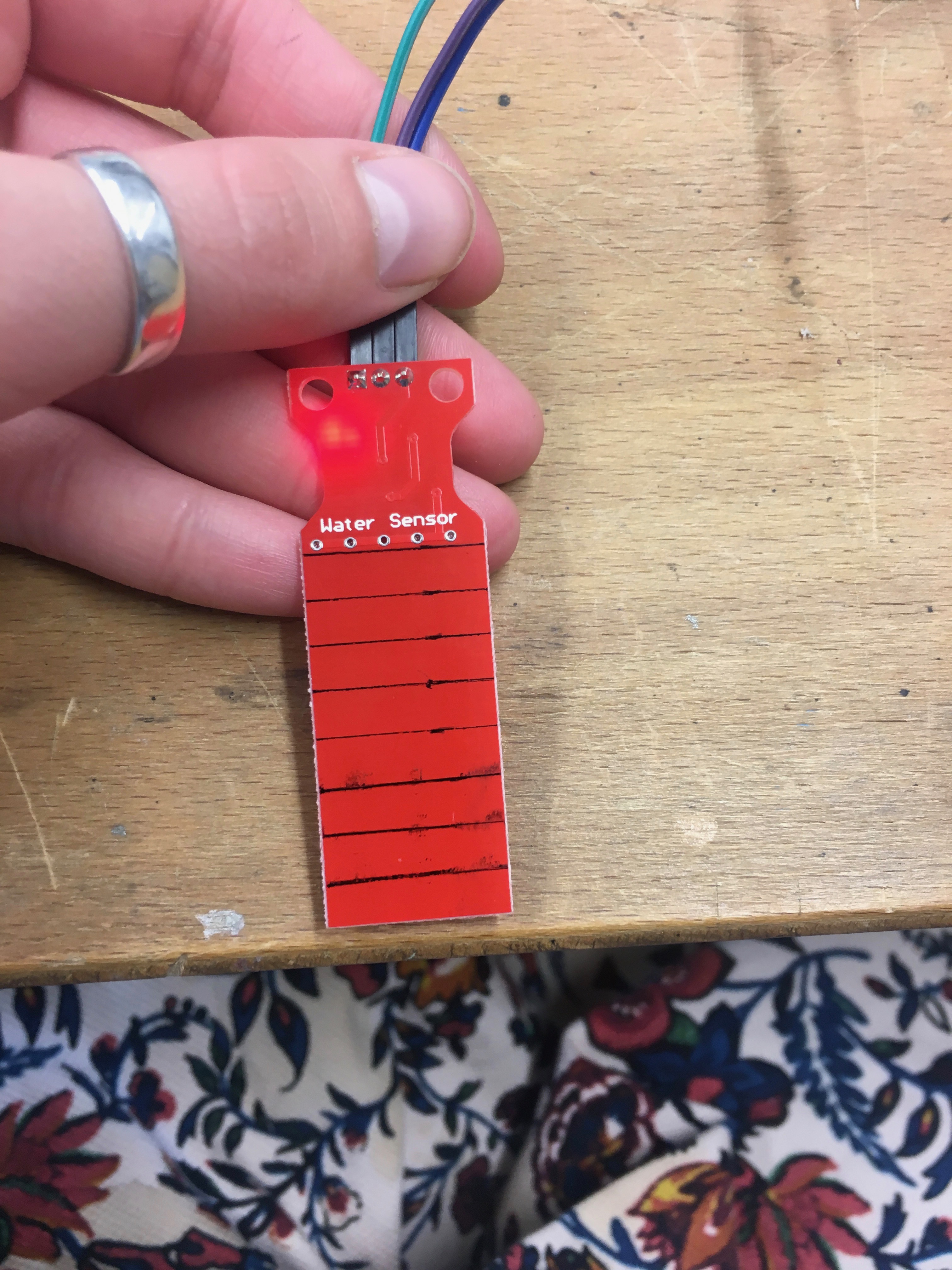
Then I decided to scale the sensor. For that I draw a lines with a distance 5 mm from each other and then checked the sensor signal for each depth.
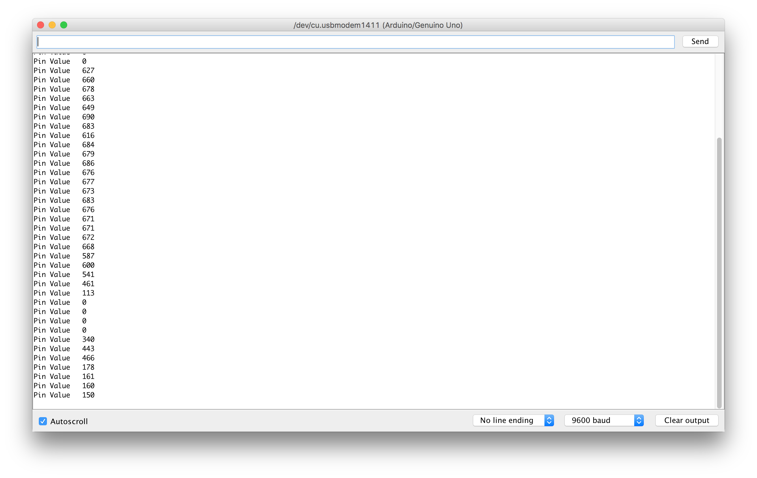
My analog values from this procedure are:
- 0mm - 510
- 5mm - 516
- 10mm - 550
- 15mm - 580
- 20mm - 590
- 25mm - 610
- 30mm - 645
- 35mm - 660
- 40mm - 680