Final Project Idea
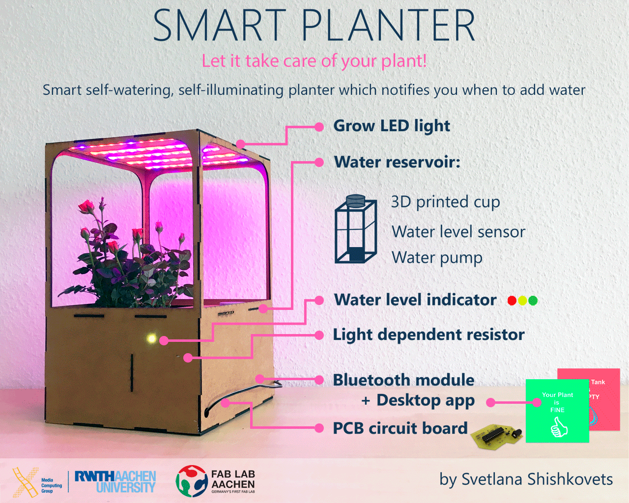
The result
And now lets talk how I did it from the very beginning...
Project Development
Here is some questions connecting to the project development.
- What is the deadline? How much time do I have left? The deadline is 11th of June, so today is 7th, only 4 day left(!!!)
- What tasks have been completed, and what tasks remain? All the development tasks has been completed, the text and video of presentation are left.
- What has worked? What hasn't? Unbelievably, but all the parts I was afraid of (electronics especially) worked pretty well. By now, everything I planned worked, not from the very beginning but works.
- What questions need to be resolved? The future of my project. By now I have some ideas, how to make it better. For example, I am not completely happy with the design of the planter body. If I had more time, I would work more on it.
- What have you learned? Everything. From web development, design to electronics and programming. I think that assignments page shows more than I can write here.
Motivation
When I was thinking about the final project idea I really wanted to make something useful for myself. So, I was sitting at my desk next to the window when I saw it:
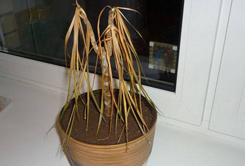
That is how I came up with an idea of self-watering smart planer. In addition it will also have a LED, so it can grow even without lights. In order to know, when to water a plant, I plan to use humidity sensor and water lever sensor, and light sensor. So, here ia the sketch of my final project:

Planning
I got this idea before the Fab Academy actually started. Even thought I did not finalise all my design ideas before May. Whenever I was able to fit time in between work, studies and the Fab Academy assignments I would try to refine my idea or start on components. In an ideal world I would have liked to incorporate each weeks assignments into my Smart Planter, but without knowing/understanding the technologies beforehand this turmed out very difficult.
So now, when I am almost at the finishing line of the FabAcademy, I am so happy to have this feeling that I can make almost anything!
Components
Now on to the practical details of the project, after some consideration I came up with the following list of components keeping in mind to use as many of the new skills we learned during the FabAcademy as possible:
- The 2D design of my press-fit planter itself and producing it with the Laser Cut. I used Laser Cut instead of Milling Machine because from the assignments I realized that laser cut is more quick and accurate than Milling machine.
- The 2D design of water reservoir and planter pot. I used Laser Cut for producing them from plexiglass.
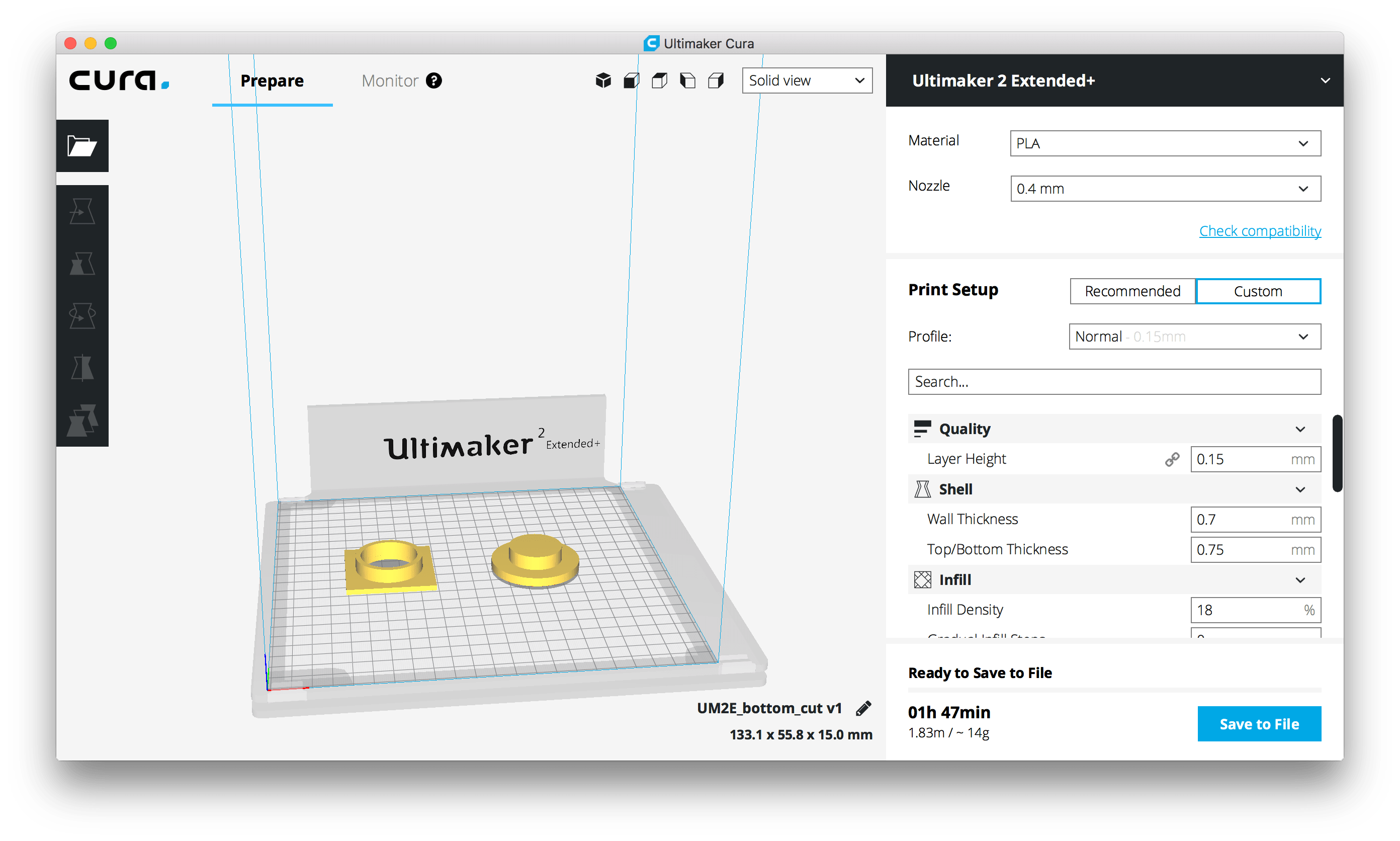
- The 3D design and 3D Printing a cup for the water reservoir.
- For the main features of my Smart Planter (self-watering, self-lightning) I needed the skills acquired during Input Devices, Output Devices and Embedded Programming weeks.
- Inside of my Planter will be the main board that includes an ATMEGA 328P and a bluetooth module so the Planter can communicate with a computer or a mobile device. This part includes skills from the Electronics design, Embedded Programming, Network & Communications and Interface & Application Programming weeks.
In the next sections each of these components will be elaborated in detail, and for the entire Bill of Materials (BOM) have a look at the files section at the bottom of the page.
Electronics
So I started preparing my board by writing down the list of features it needed to support, that list can be seen below:- Self-watering depending on soil humidity
- Self-lightning depending on light surrounding
- Notifying the user about the condition of water reservoir via LED that changes color on the planter itself and via the Desktop application.
After looking up the components that would not be on the board itself (bluetooth module, WS2812, water pump(12V), plant lights on strip(12V), humidity sensor, water level sensor), checking their datasheets, and checking the datasheets of the microcontrollers available to me, I decided to use an ATMega328. More info of my steps can be found at the Input & Output devices weeks documentation. As to the on board components, these were the ones I used:
- [Microcontroller] ATmega 328
- [Other] 2 MOSFET is short for Metal Oxide Semiconductor Field Effect Transistor. It is a voltage controlled field effect transistor. In my case will be used to control when to put Water Pump and special LED strip on and off. More info here.
- [Other] Non SMD photo resistor. This sensor can be used to measure the amount of light it is exposed to, in darker surroundings it will provide a higher resistance while the it will drop in lighter circumstances. More info here.
- [Other] Pinheads
- [2x3] Programming the ATmega using the VCC, RESET, MOSI, MISO, SCK & GND pins.
- [1x3] Pinheader for WS2812
- 2*[1x2] To connect Water Pump and LED Strip
- [1x2] For the serial RX/TX communication
- [1x2] For the powering Bluetooth module
- [2x2] For SDA/SCL communication(just in case)
- [1x3] For connecting humidity sensor
- [1x3] For connecting water level sensor
- [Other] 10kΩ Resistor - Protects the photo resistor from too much current.
- [Other] 2*1KΩ Resistor - Protects the MOSFET from too much current
- [Other] Crystal for measuring time including 2 capacitors. This setup is actually called an oscillator circuit.
- [Other] 10kΩ Resistor for the RESET pin on the ATmega.
- [Other] Voltage Regulator which will power the whole board by transforming the input 12V into 5V
- [Other] 2* 10µF Capasitors between ground and power before and after Voltage Regulator for smoothing the current and keeping the voltage more constant.
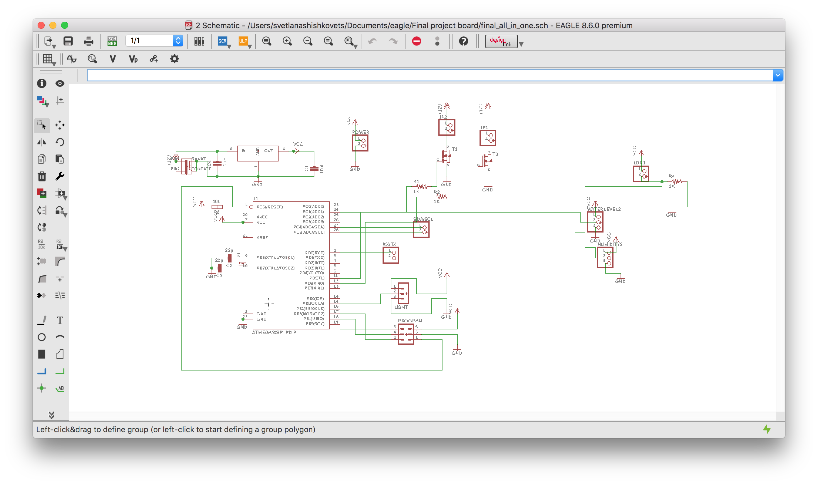
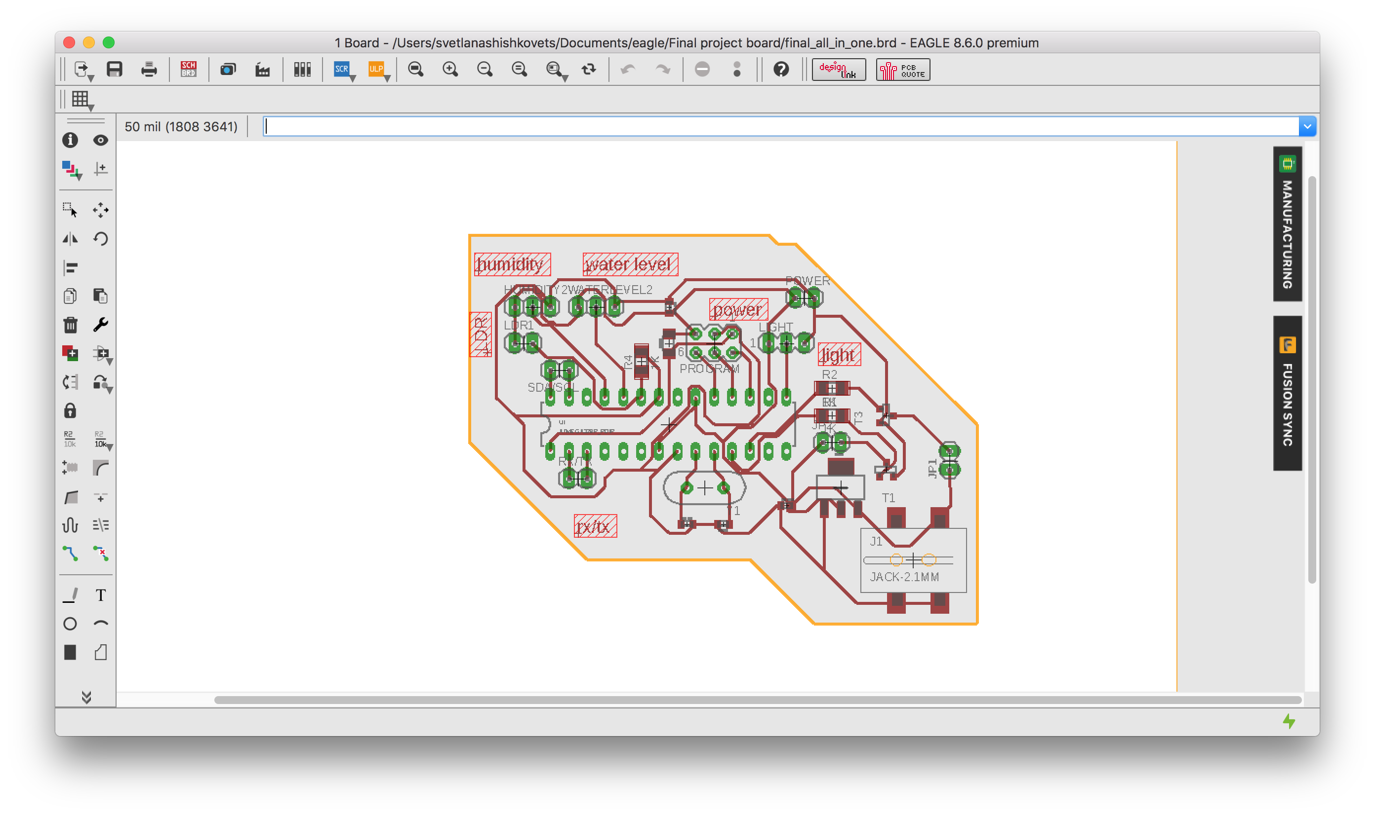
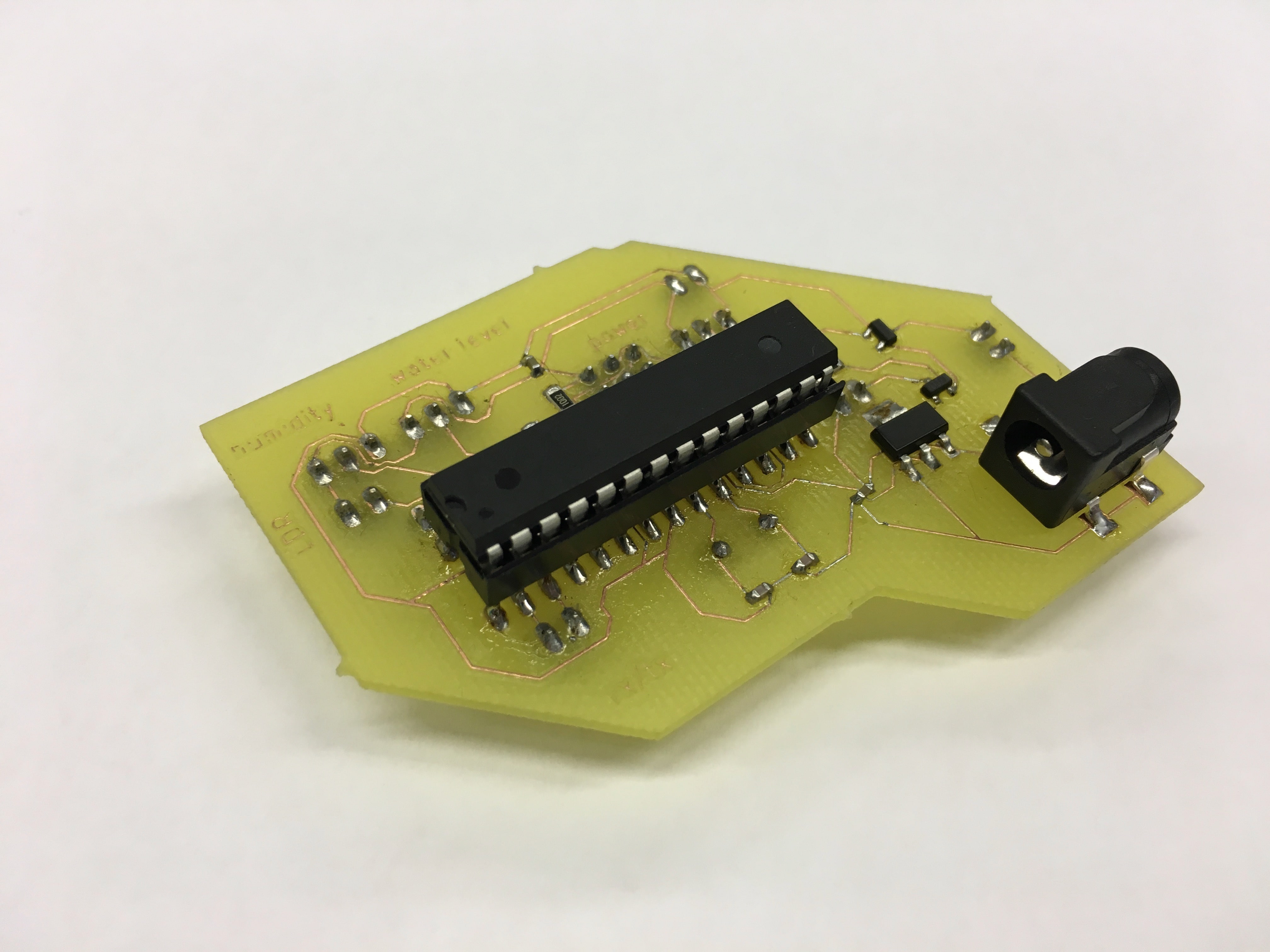
The resulting schematic and board can be seen on the image below and can be downloaded at the bottom of the page in the Files section.
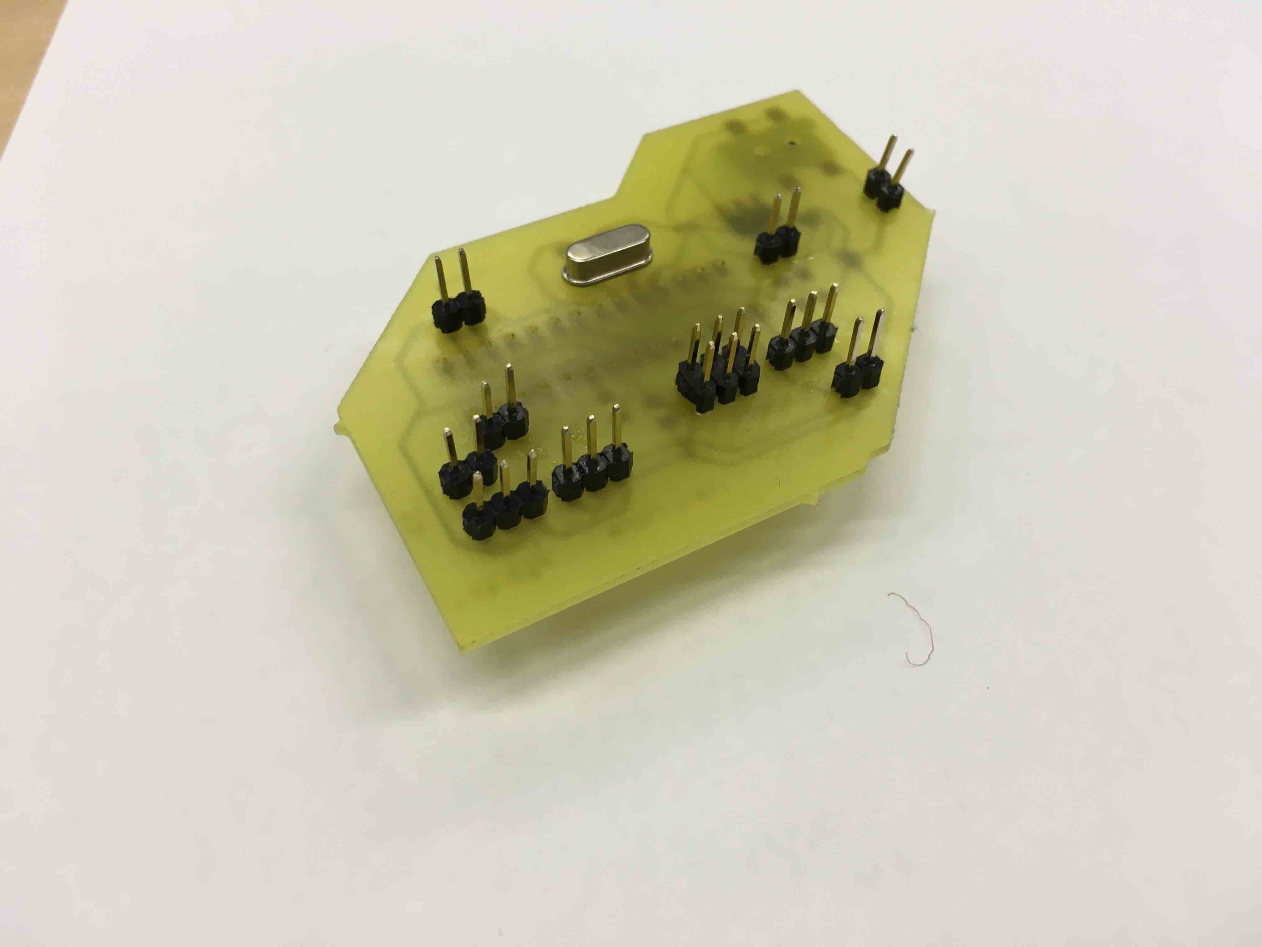
I will not get into the detail of milling and stuffing the board since I have described that process in detail in former weeks. So, here is how my boar looks like:
Programming the PCB
I used an Arduino as an ISP because this is a well documented process with which I have a bit of experience from the previous weeks. First you connect only the Arduino to your computer without the board attached to it, then you open up the ArduinoISP example in the Arduino IDE and upload it. Then I connected my board to the ISP using the 6x1 pinheader to program the ATMega328 itself. More info of my steps can be found at the Input & Output devices weeks documentation.
Below you can find a code with a lot of explanation comments, enjoy :)
P.S. the code can also be downloaded from the file section.
#include "FastLED.h"
// define LED as an output for water level
#define NUM_LEDS 1
#define DATA_PIN 9
// determine input sensors
int sensorPinLDR = PC0; // select the input pin for LDR
int sensorValueLDR = 0; // variable to store the value coming from the LDR sensor
int sensorPinWater = PC1; // select the input pin for water level sensor
int sensorValueWater = 0; // variable to store the value coming from the water level sensor
int sensorPinHumidity = PC2; // select the input pin for humidity sensor
int sensorValueHumidity = 0; // variable to store the value coming from the humidity  sensor

// Define the array of leds
CRGB leds[NUM_LEDS];

void setup() {
  Serial.begin(9600); //sets serial port for communication
  FastLED.addLeds(leds, NUM_LEDS);
   // MOSFET PINS
  pinMode(PD5, OUTPUT);// PUMP
  pinMode(PD6, OUTPUT);// LIGHTS
    }
void loop() {
  sensorValueLDR = analogRead(sensorPinLDR); // read the value from the sensor
  sensorValueWater = analogRead(sensorPinWater);
  sensorValueHumidity = analogRead(sensorPinHumidity);

  // Water level
 if (sensorValueWater < 10) {
    Serial.println("NO WATER IN HERE!");
    Serial.print(0);
    leds[0] = CRGB::Red;
    FastLED.show();
  }
   else if (sensorValueWater < 400) {
    Serial.println("NO WATER IN HERE!");
    Serial.print(1);
    leds[0] = CRGB::Yellow;
    FastLED.show();
  }
  else{
    Serial.println("ENOUGHT WATER IN HERE!");
    Serial.print(1);
    leds[0] = CRGB::Green;
    FastLED.show();
  }

  // Humidity
   if (sensorValueHumidity < 110) {
    Serial.println("Dry Soil!");
     digitalWrite(PD5, HIGH); //turn the pump on
  }
  else{
    Serial.println("Moist soil");
     digitalWrite(PD5, LOW);// turn the pump off
  }

  // LIGHT
   if (sensorValueLDR < 400) {
    Serial.println("Not enought Light");
     digitalWrite(PD6, HIGH);// turn the Lights on
  }
  else{
   Serial.println("Enought Light");
     digitalWrite(PD6, LOW); //turn the Lights off
  }

 delay(1000);

}
And here is the video how the system works:
Programming the application
DISCLAIMER: This part is the same as in Application programming & Network assignment , but I will still have it here in order to minimize the page hopping!
I used an HC05 bluetooth module (Datasheet ). The module uses a serial connection over the RX and TX pin and my final board processor ATmega328 has such a pins, there should be no problem. Here is an instruction, how to set and connect the bluetooth module:
- Connect EN pin to 5V (high level) and GND to ground
- Hold RESET button while powering on
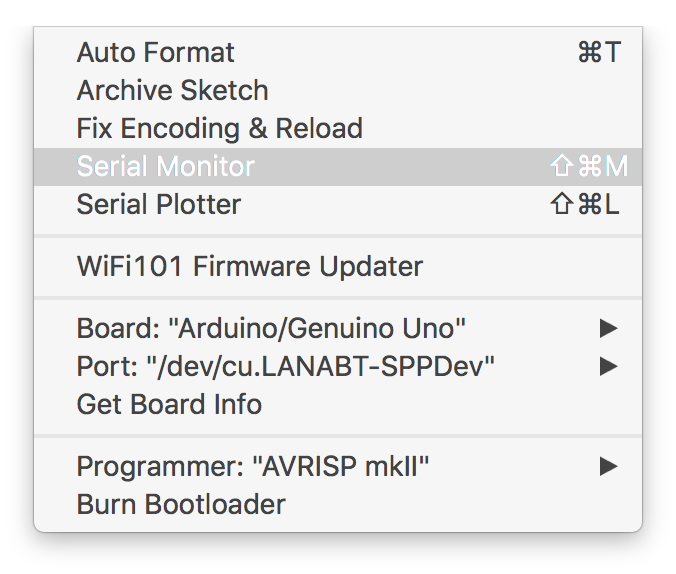
- Use Arduino serial monitor to write AT commands to bluetooth module and configure name, password and etc(All the commands can be found in datasheet above)
- Repower without EN pin and without holding RESET button and connect to bluetooth device normally
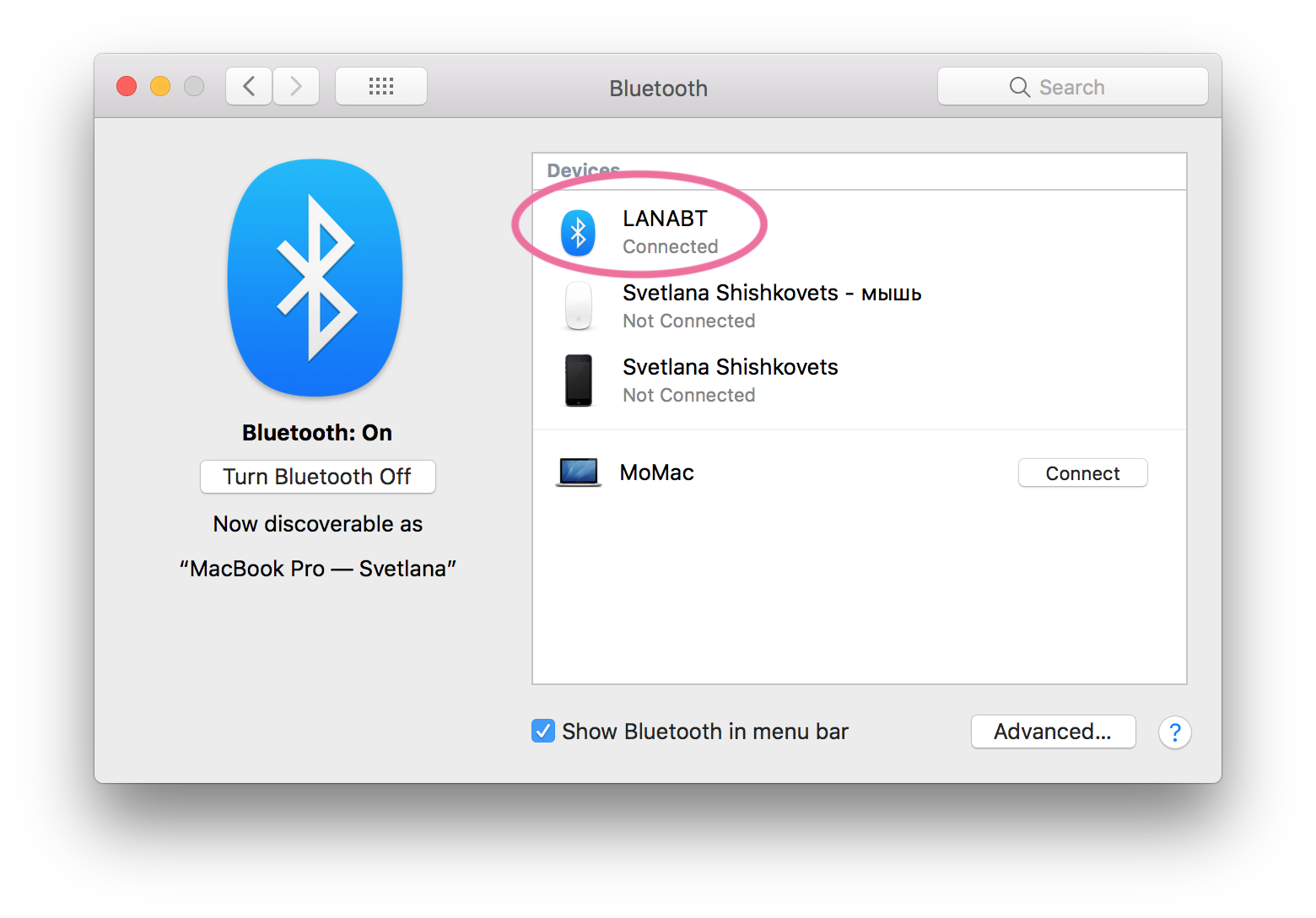
After that I could find bluetooth on my laptop and connect it:
After that I programmed my board using serial communication:
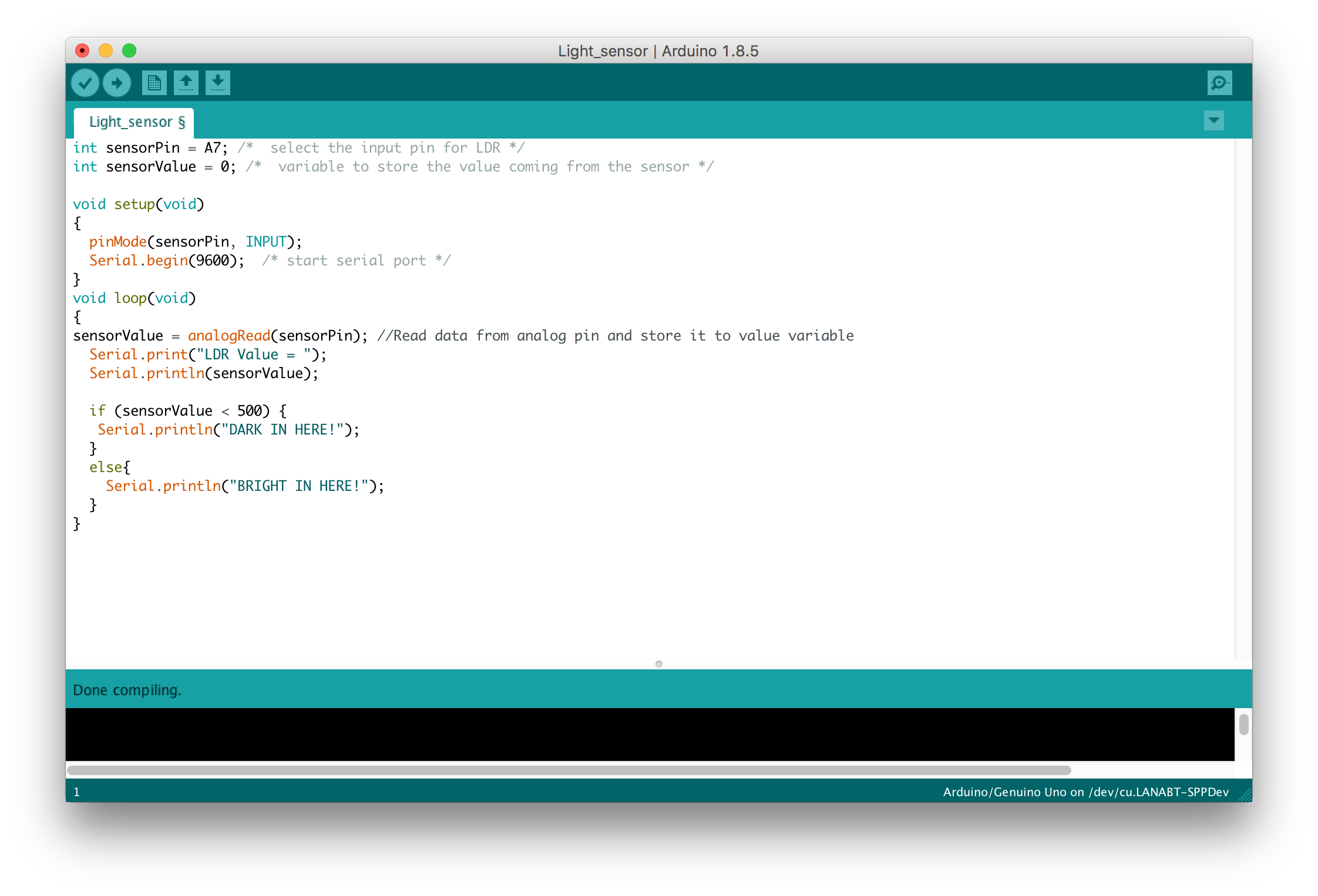
So now, if I will open serial Monitor for a device - Bluetooth, I will see what bluetooth module receives :
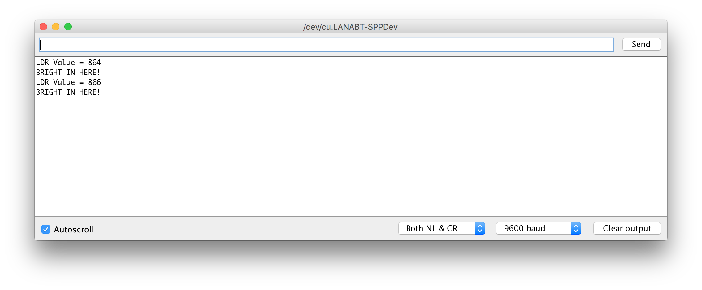
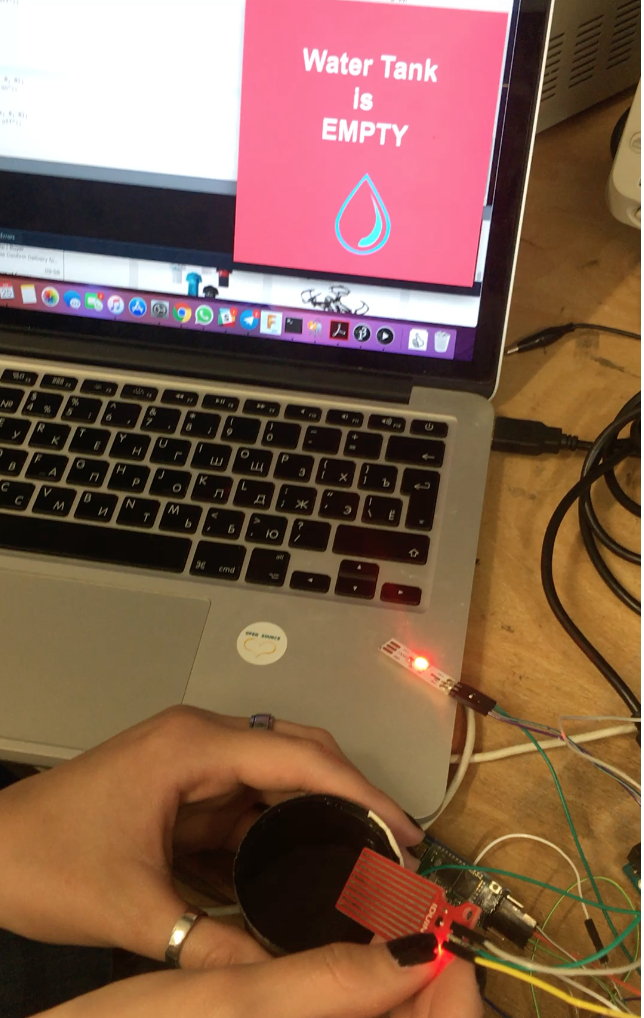
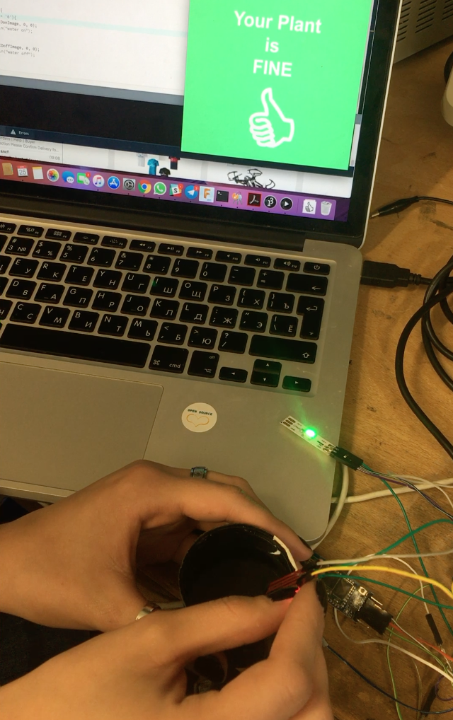
I did set up a processing app to work with the bluetooth module on my PCB. The app simply connects to the bluetooth module and receives the information (0 when water tank is empty and 1 when it is full).
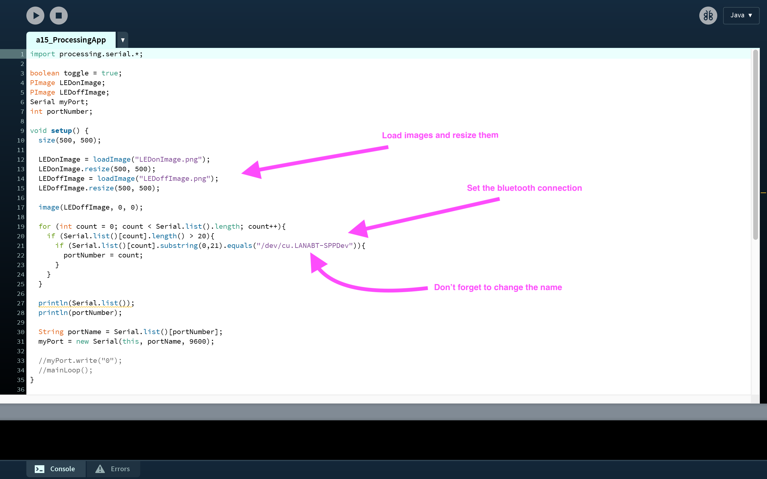
import processing.serial.*;
boolean toggle = true;
PImage LEDonImage;
PImage LEDoffImage;
Serial myPort;
int portNumber;
void setup() {
size(500, 500);
LEDonImage = loadImage("LEDonImage.png");
LEDonImage.resize(500, 500);
LEDoffImage = loadImage("LEDoffImage.png");
LEDoffImage.resize(500, 500);
image(LEDoffImage, 0, 0);
for (int count = 0; count < Serial.list().length; count++){
if (Serial.list()[count].length() > 20){
if (Serial.list()[count].substring(0,21).equals("/dev/cu.LANABT-SPPDev")){
portNumber = count;
}
}
}
println(Serial.list());
println(portNumber);
String portName = Serial.list()[portNumber];
myPort = new Serial(this, portName, 9600);
//myPort.write("0");
//mainLoop();
}
char water = 0;
char last = 1;
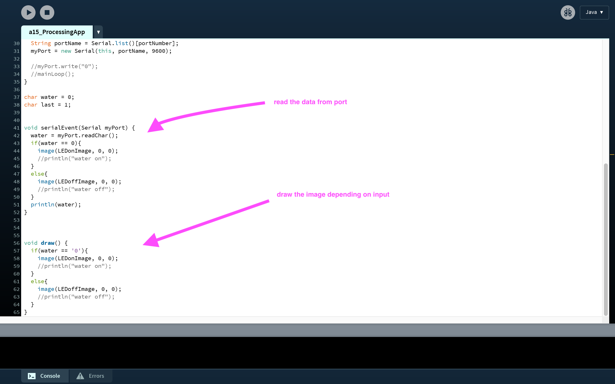
void serialEvent(Serial myPort) {
water = myPort.readChar();
if(water == 0){
image(LEDonImage, 0, 0);
//println("water on");
}
else{
image(LEDoffImage, 0, 0);
//println("water off");
}
println(water);
}
void draw() {
if(water == '0'){
image(LEDonImage, 0, 0);
//println("water on");
}
else{
image(LEDoffImage, 0, 0);
//println("water off");
}
}
So, that how it looks:
Planter production
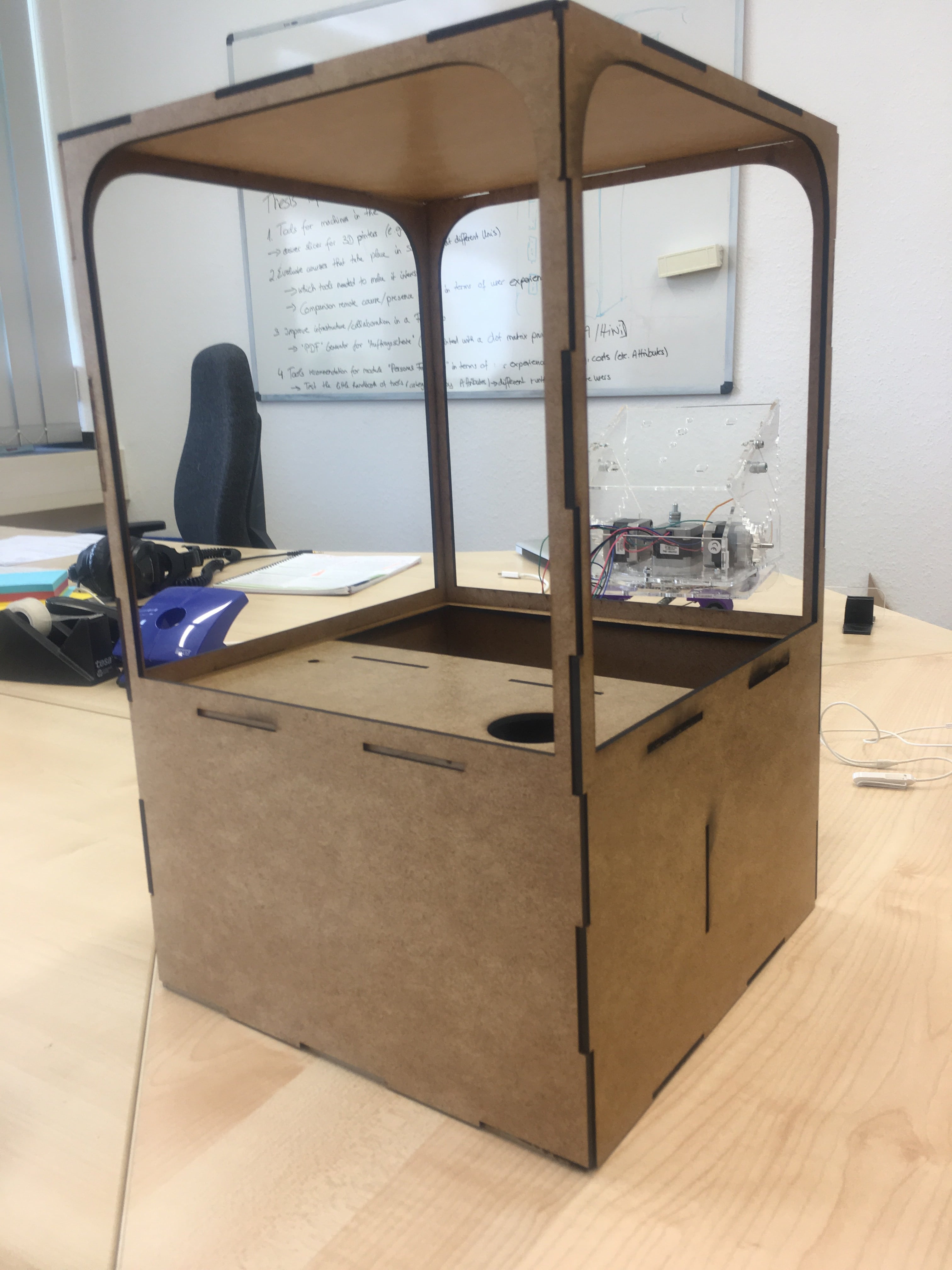
I created a press-fit design of my Planter using Autodesk Fusion. This design is almost the same one as I did for the Computer Controlled Machining Week .
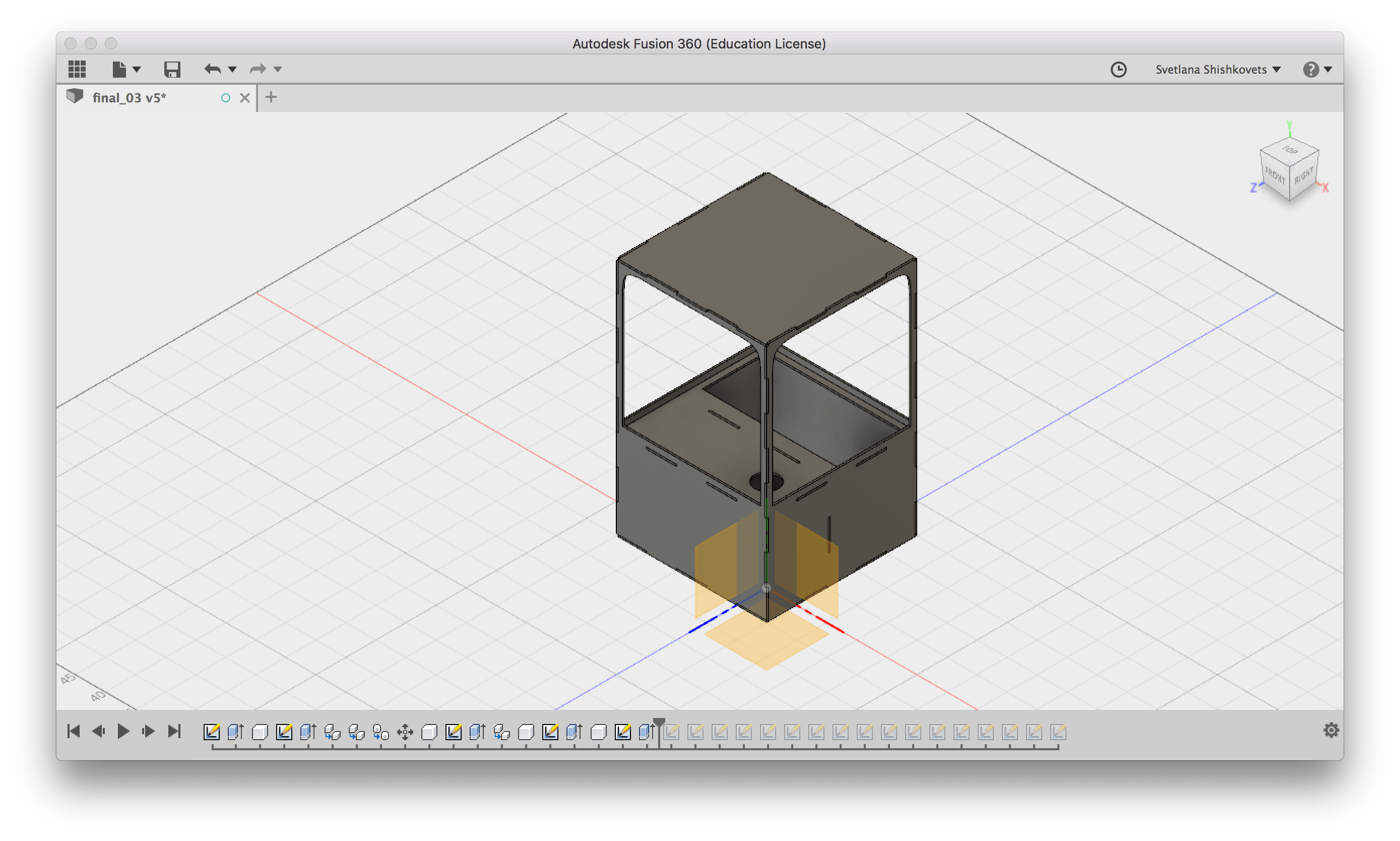
Next step was to laser cut it. It was not obvious, how to get a 2D desing from 3D, so I found a nice trick. In order to do that, I projecte my pieces into a sketch and saved the sketche as .DXF files. Basically, you need to project you component into a new figure. Here is a step-by-step instruction:
At the file section you can fins both: the .f3d model and .zip with vector design of each part.
So after cutting I putted all parts together:
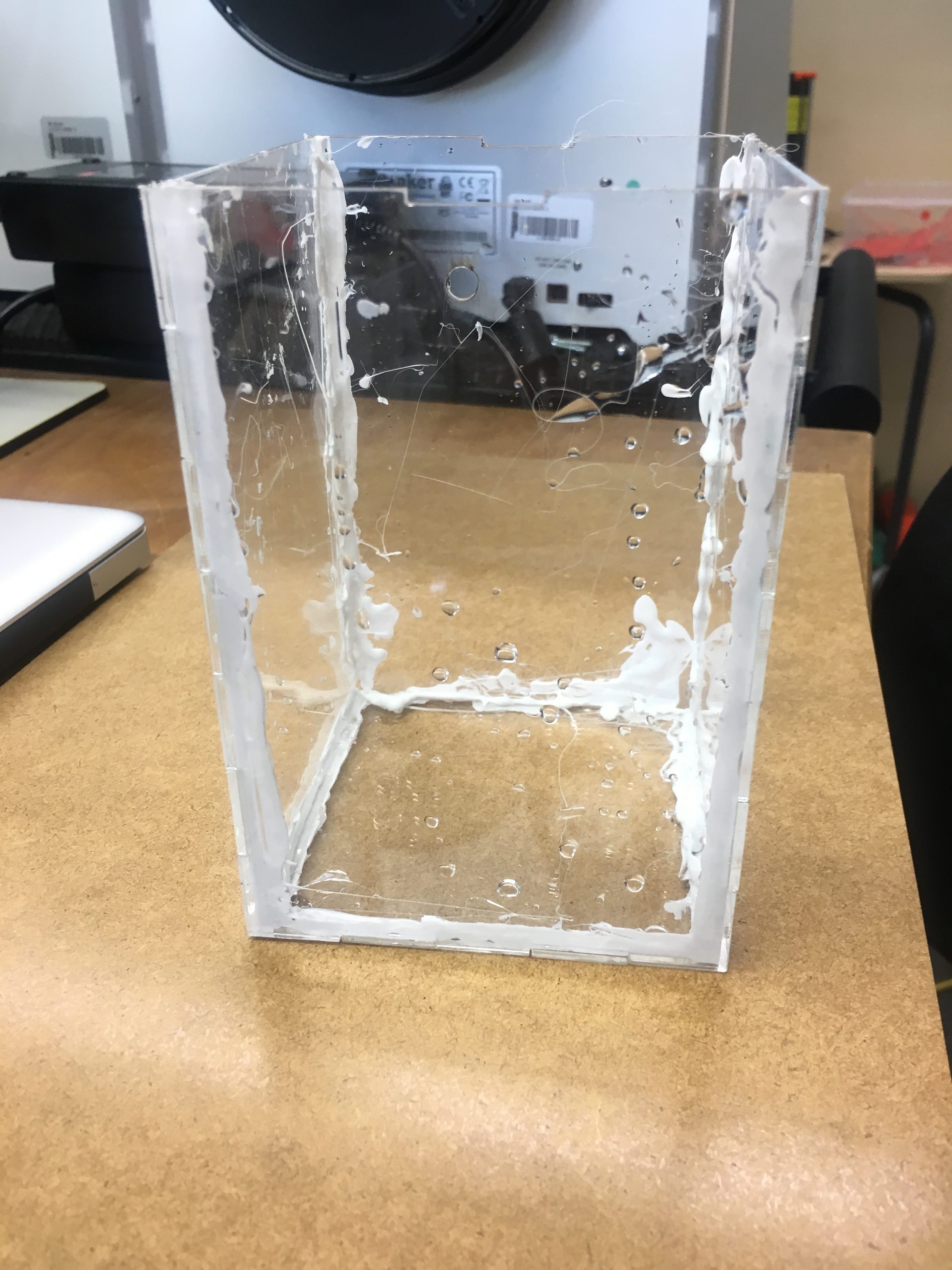
I also did the water reservoir and pot for plant using laser cut. Making addition pot was not a part of my initial idea. Since the body is made of the MDF, I thought that contact with water might cause some problem, that is why I made an extra pot in order to avoid this contact. I am not going to explain you the details of design, since it is just a simple boxes. I made the design using this online tool. The .svg designs could be found in the file section. The water reservoir needed a bit more effort, since it should be water waterproof. I used hot glue pistol for that:
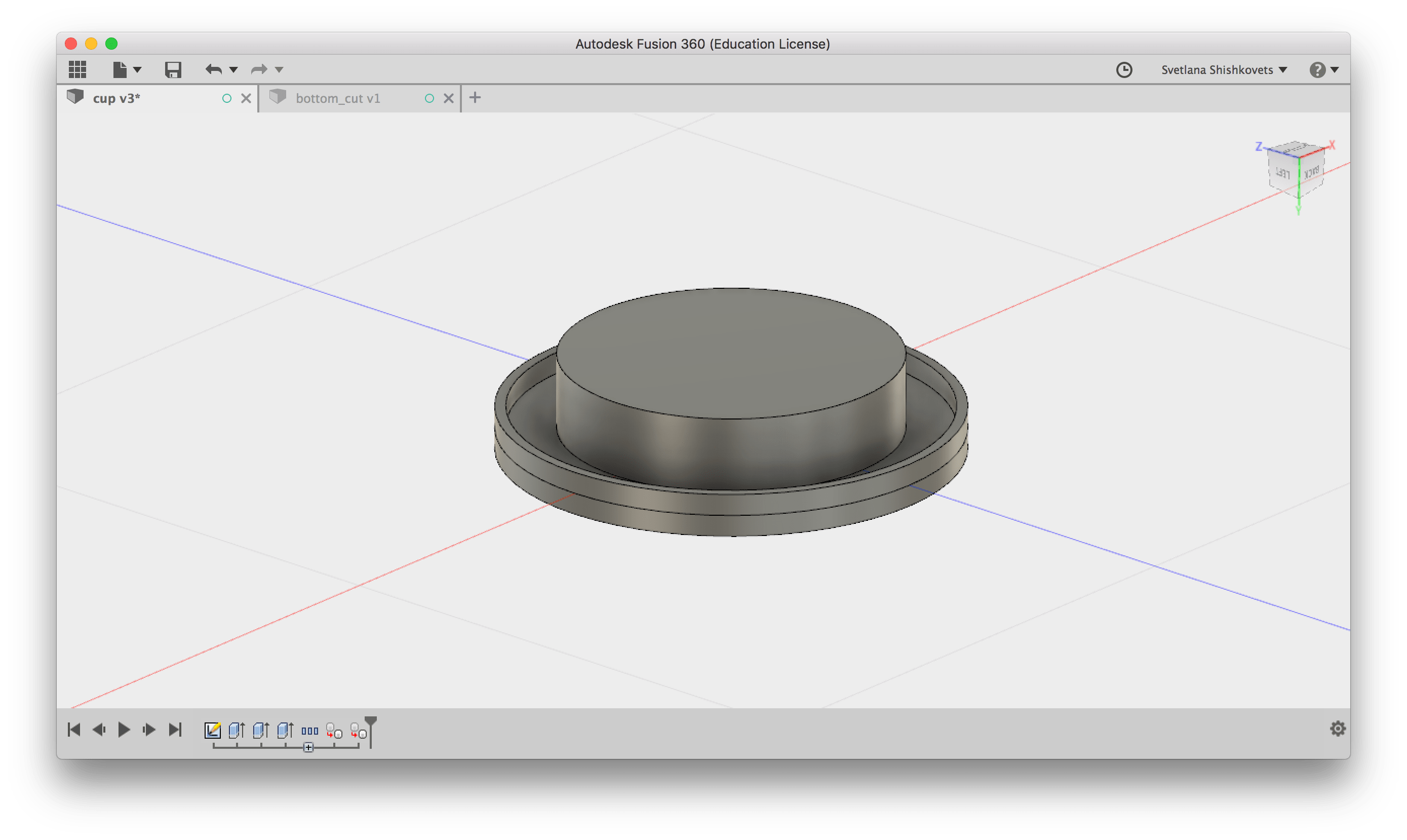
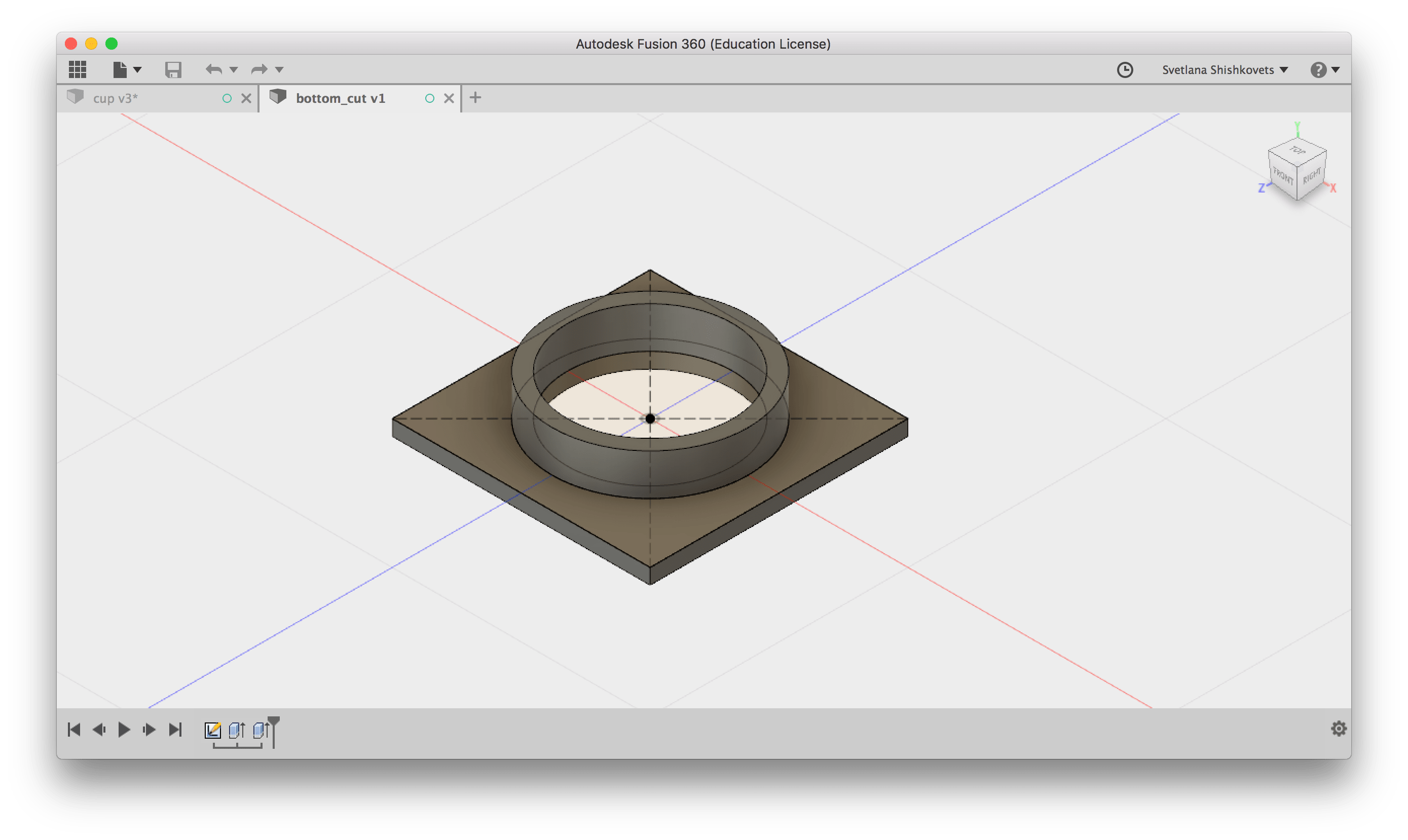
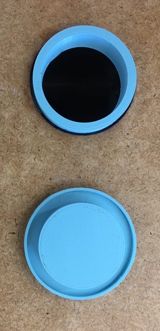
Cup production
Next step was designing and producing the top part and cup for the water reservoir. As always, I did the design in Autodesk Fusion. I did a design of platform with hole and the cup itself. You can download .f3d as well as .stl files below.
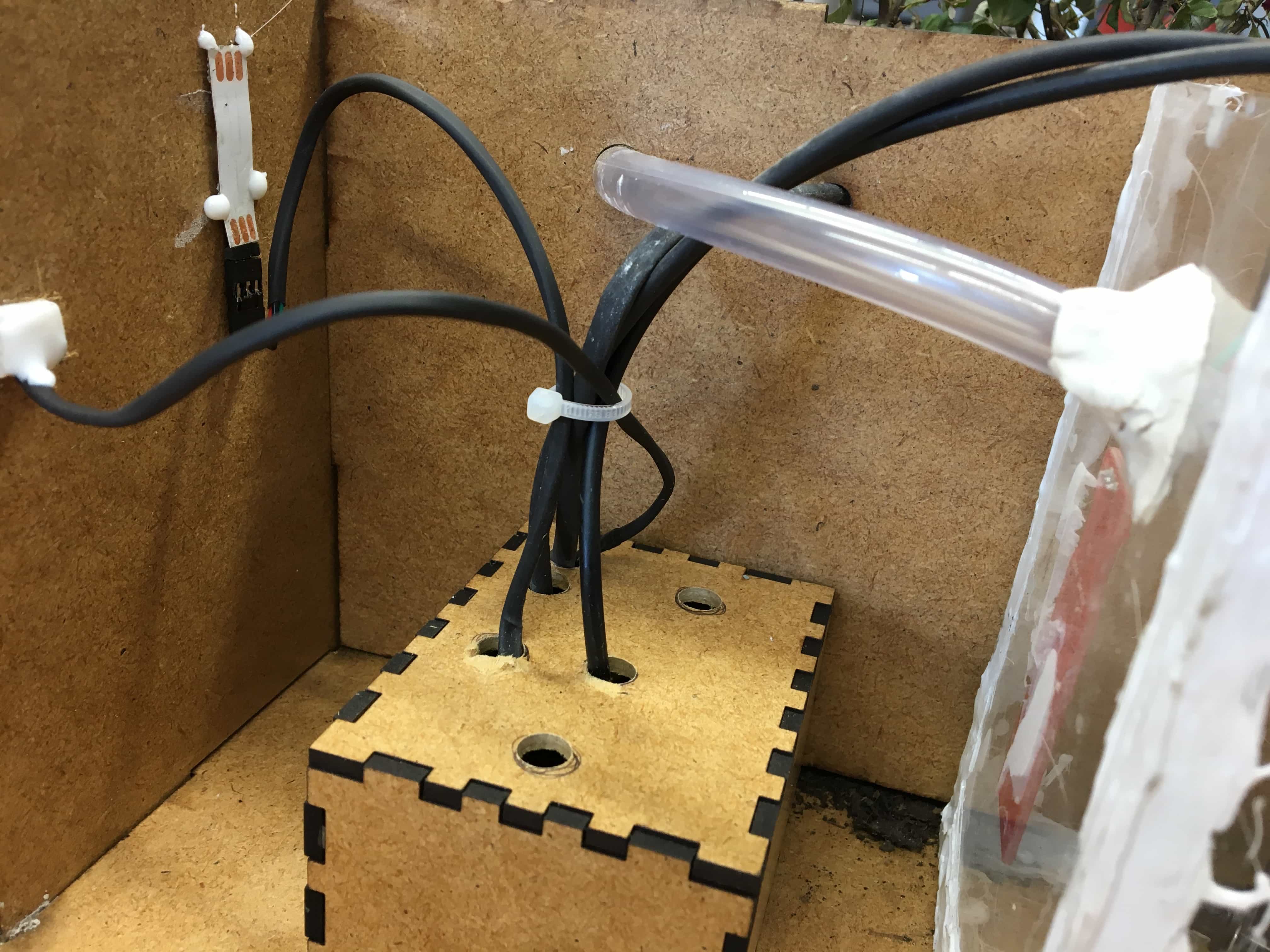
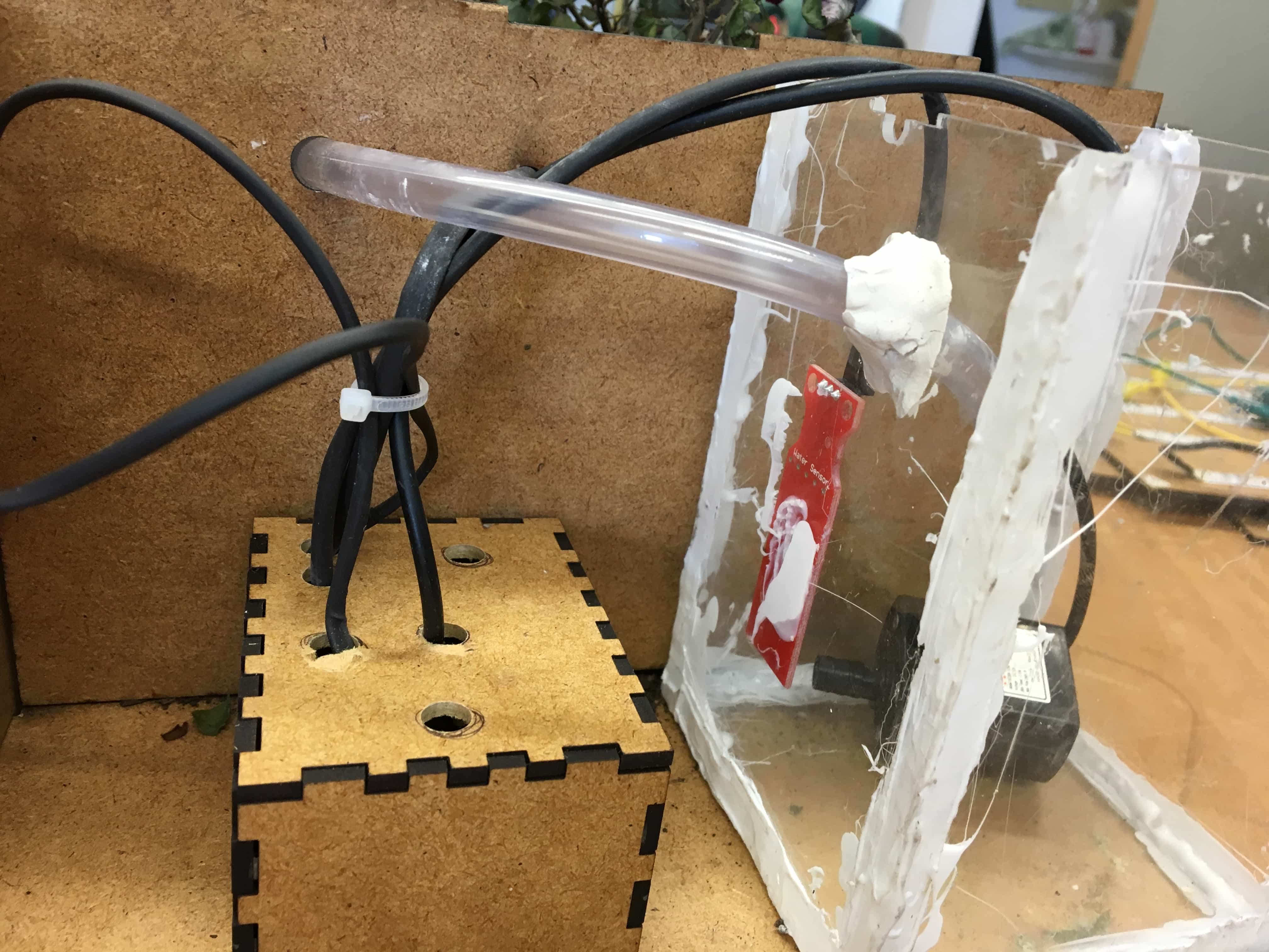
Assembly
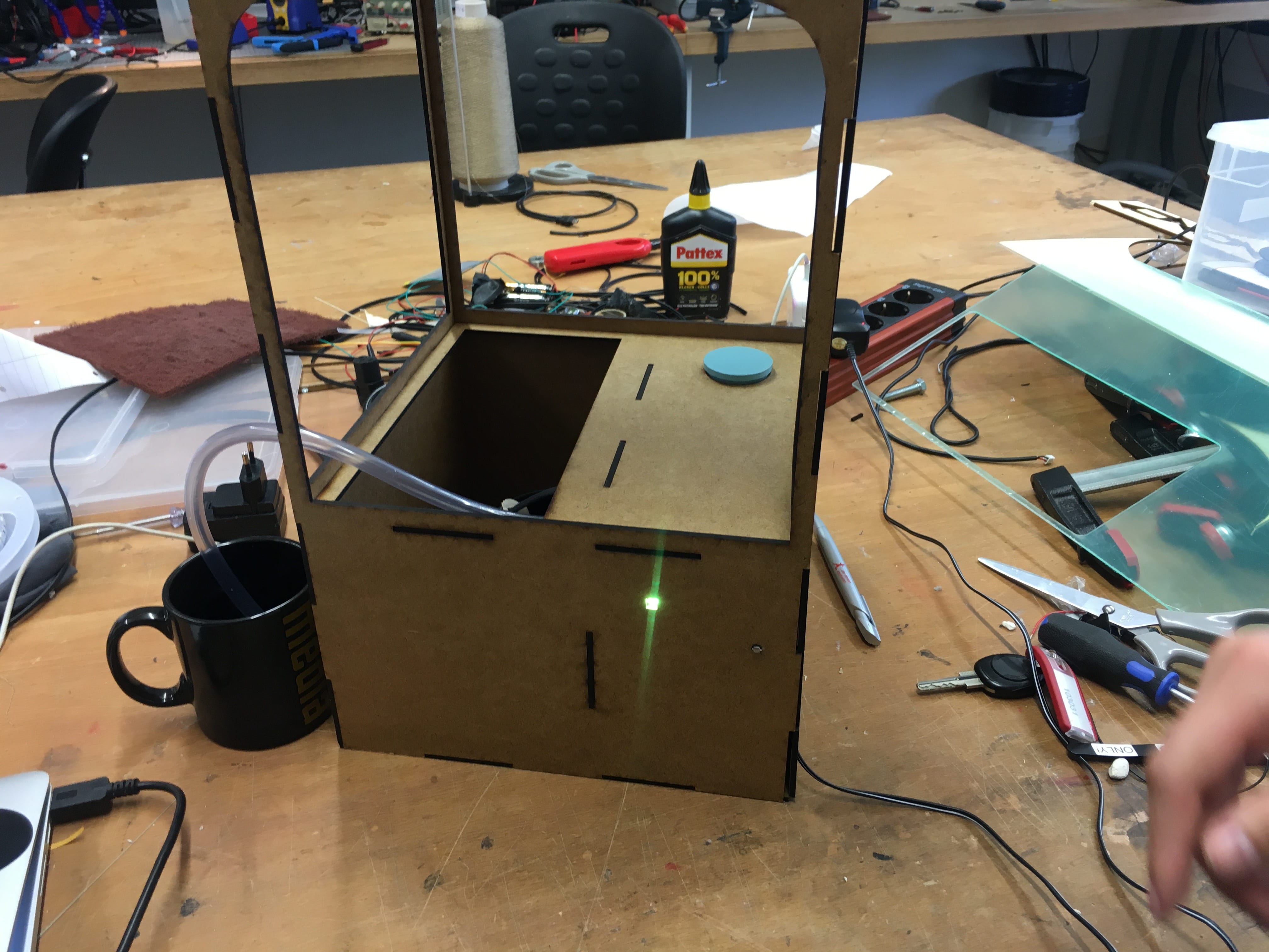
Next step was to put it all together. I would recommend to be very careful with water and electricity, since they are just next to each other. So first I did the test of mmy system without any planter or soil:
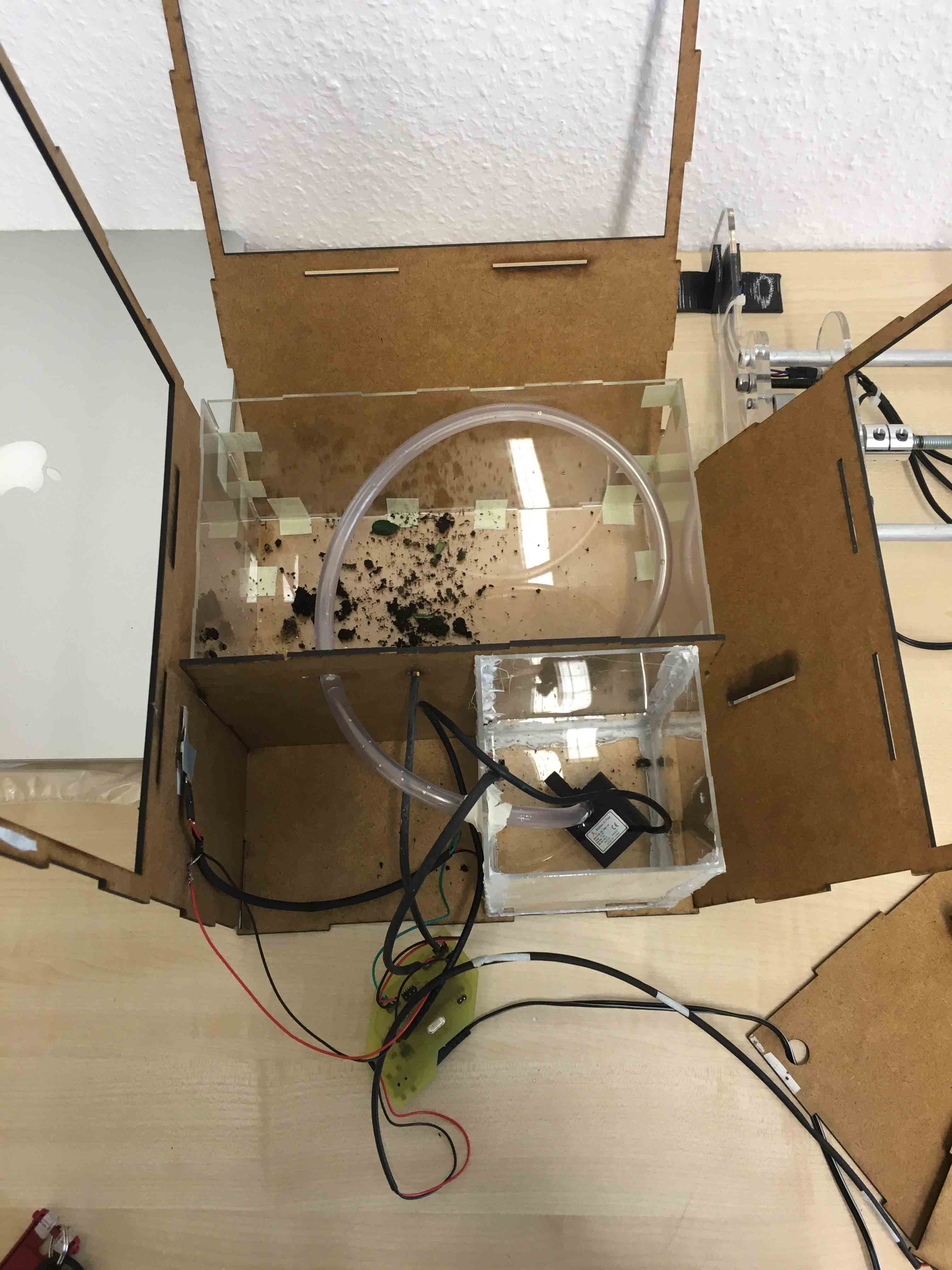
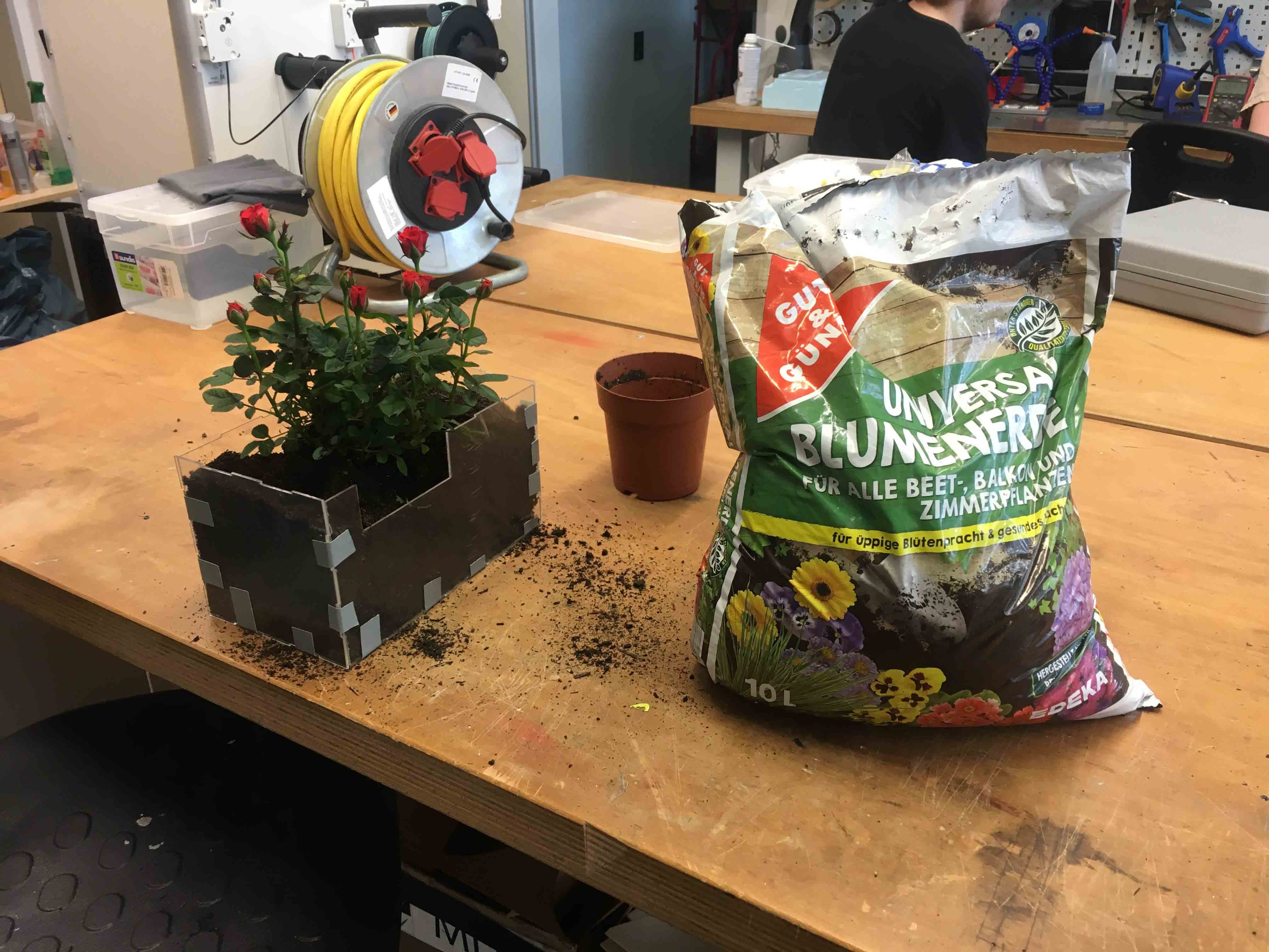
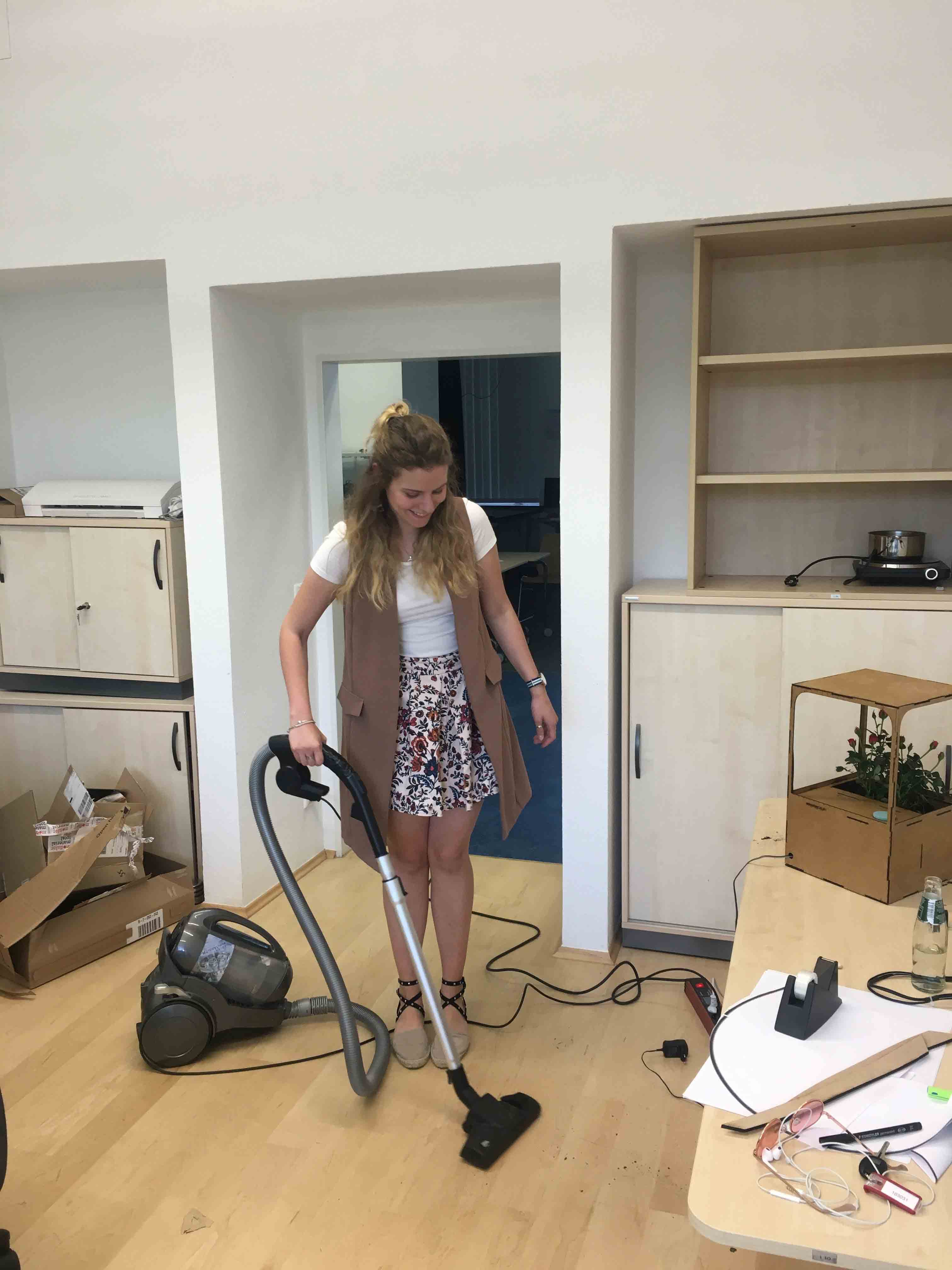
Then I planted my roses. And of course, cleaned after my mess :)
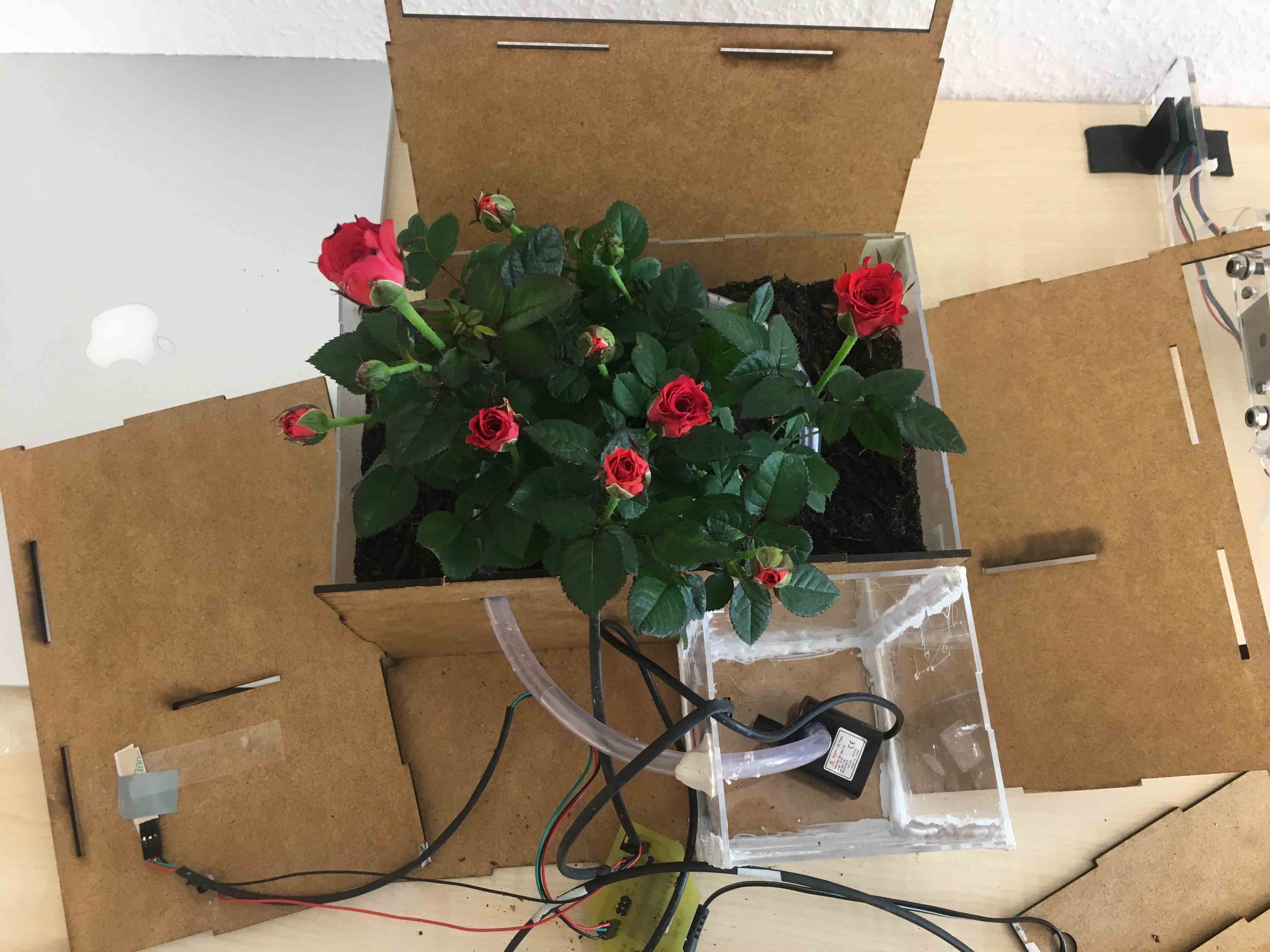
For more secure I build the box for the board and glued the light sensor and WS2812:
THE END!
P.S. It was a great journey. I want to thank the FabAcademy for such a great experience and quick learning. What is more, thank the The Media Computing Group of RWTH Aachen for being extremely supportive and very helpful. And I appreciate my colleagues, Anke and Matthias, for making this journey pleasant. That was much fun, I will miss it!