Computer-Controlled Cutting
![]()
Introduction
For the assignment we were asked start using CNC machines like a laser cutter to create physical objects from the designs. Most laser cutters are limited to cutting and engraving in 2D. However, there is the possibility to create 3D objects with a laser cutter. Two of those techniques are creating press-fit construction kits and cutting patterns which make previous solid material bendable. In comparison to 3D printing, laser cutting is usually faster and cheaper. Therefore, it is a great method for doing fast prototypes before you invest your time into a 3D printed object.
Getting to know the laser cutter
In order to "meet" the laser cutter we were asked to make a group assignment in order to test the laser cutter settings. The relevant documentation of how we tested kerf, speed, and power of the laser cutter can be found here. The laser cutter that is available in our FabLab is a Epilog Zing 24 Laser, with a work area of maximum 610 mm by 305mm(more information can be found here.).
The laser cutter v.1
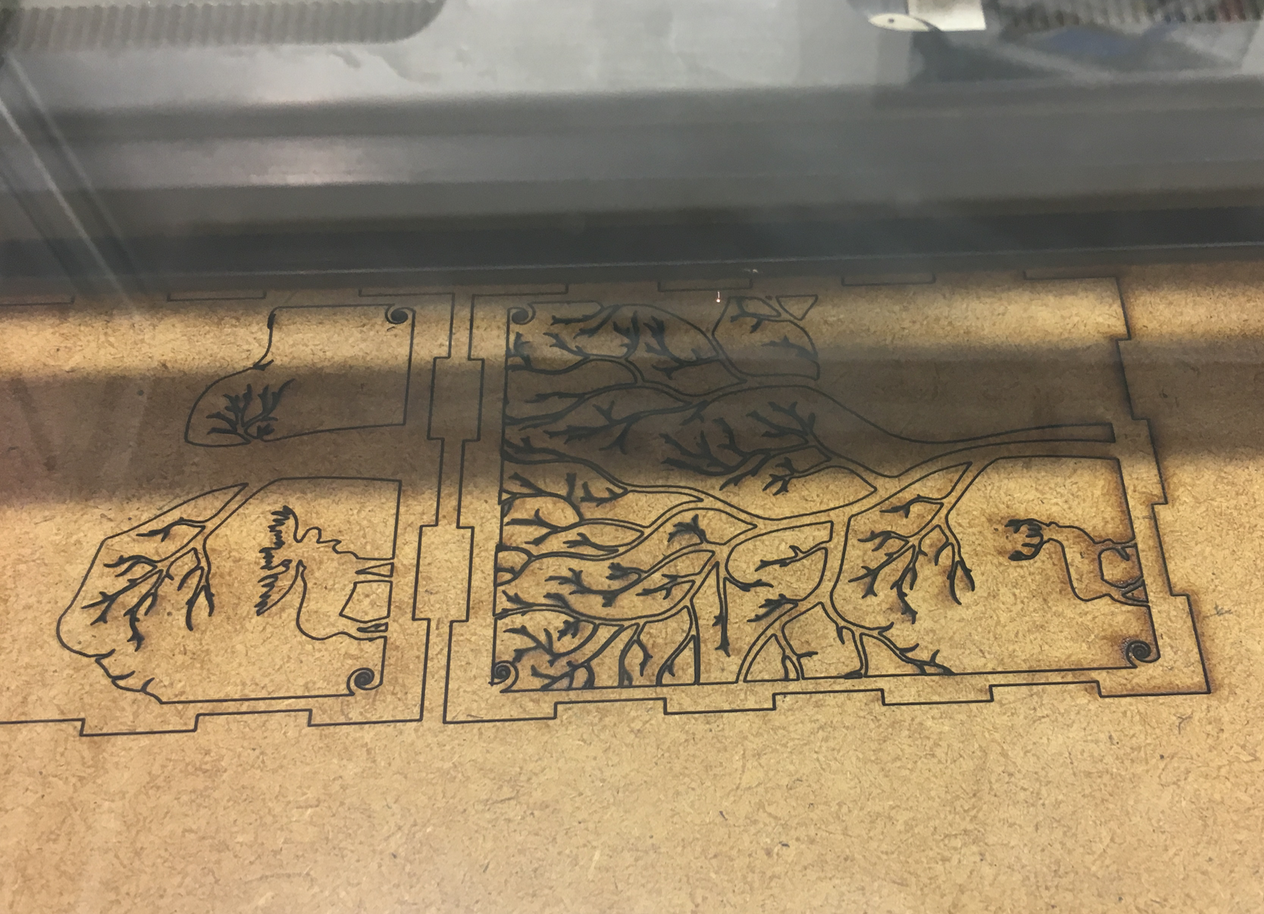
The main task for this weeks assignment consisted of designing and making a parametric press-fit construction kit. So, I started just by directly typing in Google "press-fit construction kit". I still don't know how I ended up at that page, where I found an awesome candle holder from Dresden FabLab. I thought it is really great idea for a present for my Mum at Russian Mother's Day(8 March). Since the design was made not by me, I wanted to add something from myself, that is why I added engravings. For that I downloaded a free for non-commercial use font. In order to put it on the bottom of my candle I used Inscape. There is a small hint how to use downloaded fonts in Inscape on Mac. So, the steps are the same as in our group page, so here is a quick recap:
- Put the chosen material on the laser bed and select it in settings.
- Point the focus on the laser cutter itsel
- Prepare the laser job in VisiCut and send the job to the machine.
- Wait patiently for the job to finish, always keeping an eye on it for safety reasons.
- Then wait another 5 minutes before opening it and taking the piece out.
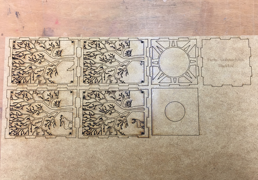
So, when I put all pieces together:
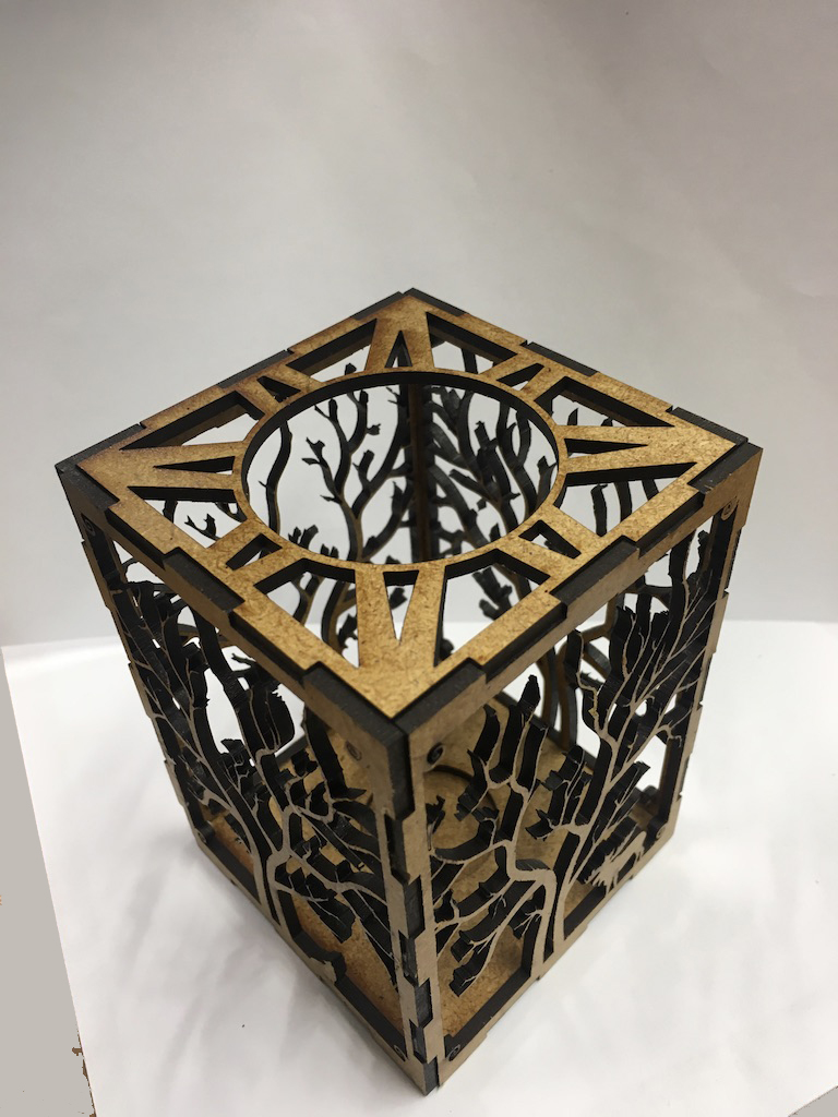
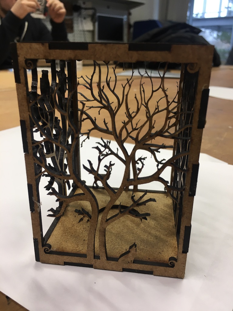
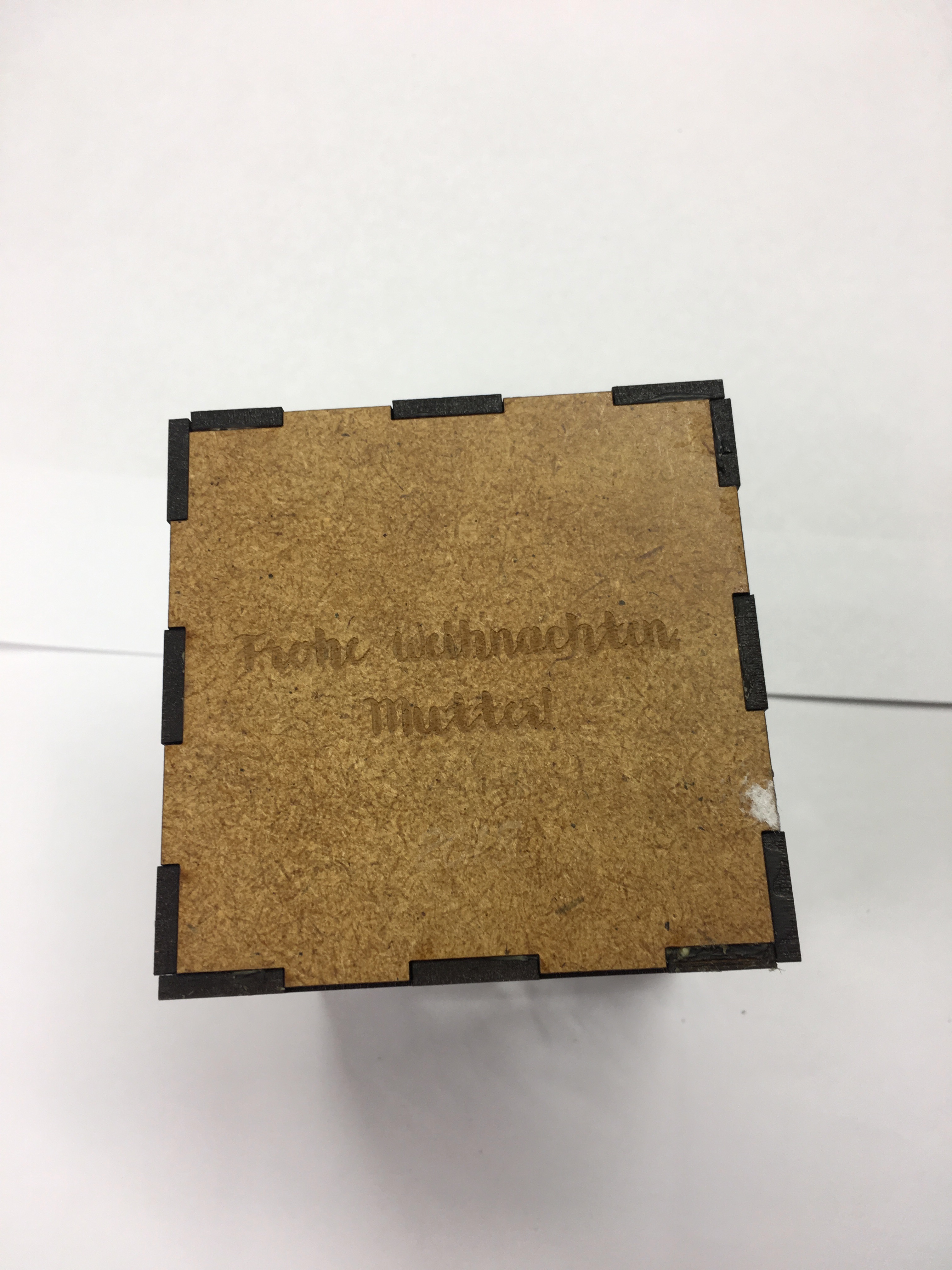
Only after looking at previous year Fab Academy assignment page I realized, that I forgot about a part "which also had to have the ability to be assembled in multiple ways." That is why the next section is ...
The laser cutter v.2
Designing the Press-Fit Kit
During working on previous assignment, I learned how to use a OpenSCAD. Since working with that was not that easy for me (writing lines of code, not somehow "draw" objects) I made myself a challenge to use the same tool for next assignment as well. What is more, it is really easy to use parametric design there. So, whay is parametric design and why is it so useful? Parametric design is a design that is governed by certain logic which includes algorithms (to devise the logic) and these algorithms further include certain parameters which can be varied to see multiple outcomes. (Mostly to do with geometry of the structure). It is good, if you did not figured out the final sizes of you design, but know the relation between them. What is more, it is good if you want to fave different number of parts in design (such as cuts in my next design).
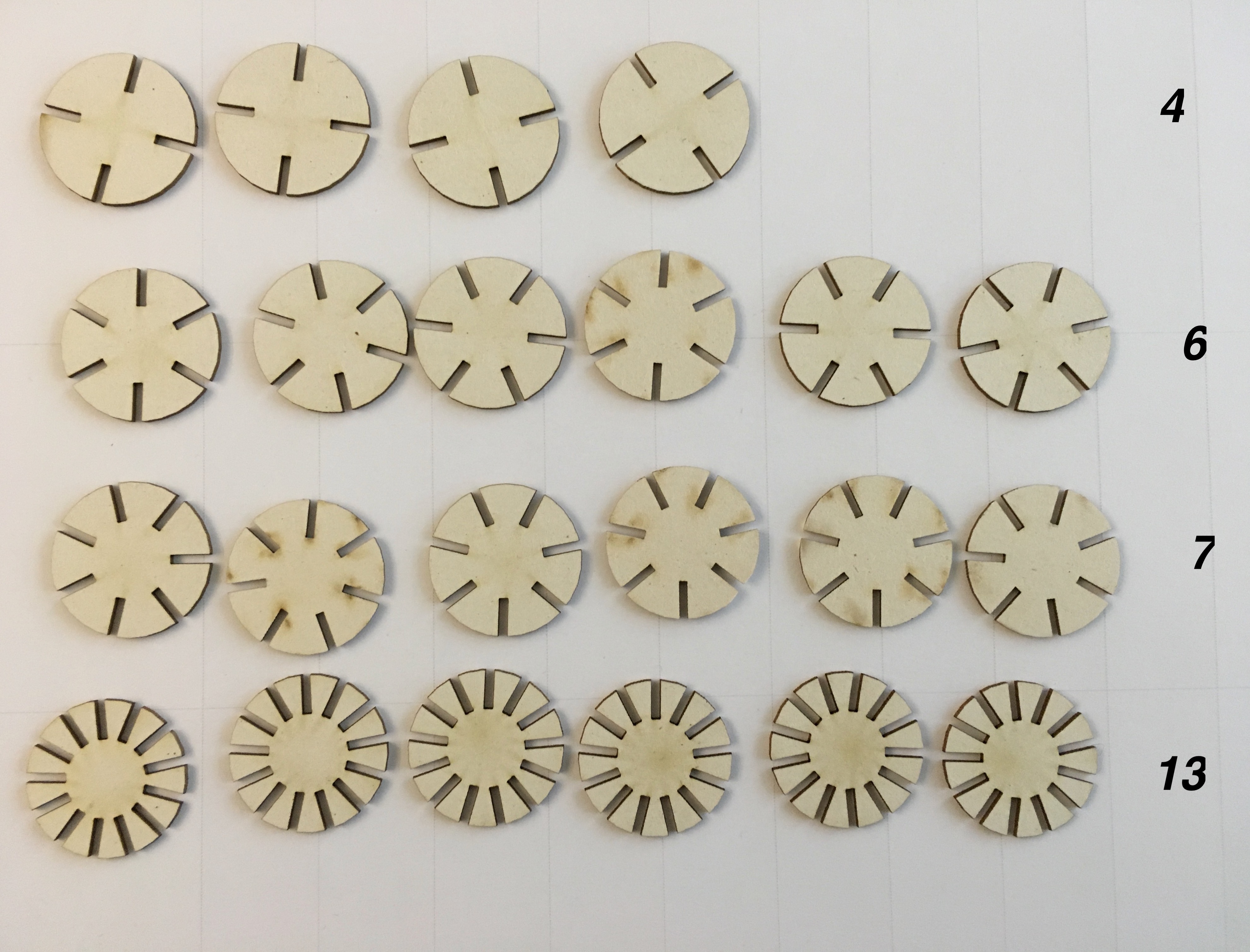
Thanks again to Paulina and her great way to document everything, I was somehow able to skip the "damn" Approach and wrote my code in an Improved one. Since I made a Parametric design, I could change not only size of circle and size of "cuts", but also their number.
OpenSCAD code is really easy to read and understand. First, you define the variables(you can change them anytime):
                    circle_size = 40;
                    jointWidth = 3;
                    jointHeight = circle_size/2;
                    sides = 6;
Make a circle:
circle(circle_size);
Using "difference" cut the pieces from the circle
                    step = 360/sides;
                    for(rotation = [0 : step : 360]){
                    offset = circle_size/2;
                    rotate(rotation, [0, 0, 1])
                    translate([-jointWidth/2, offset , 0])
                    square([jointWidth, jointHeight], 0);

Making the Press-Fit Kit
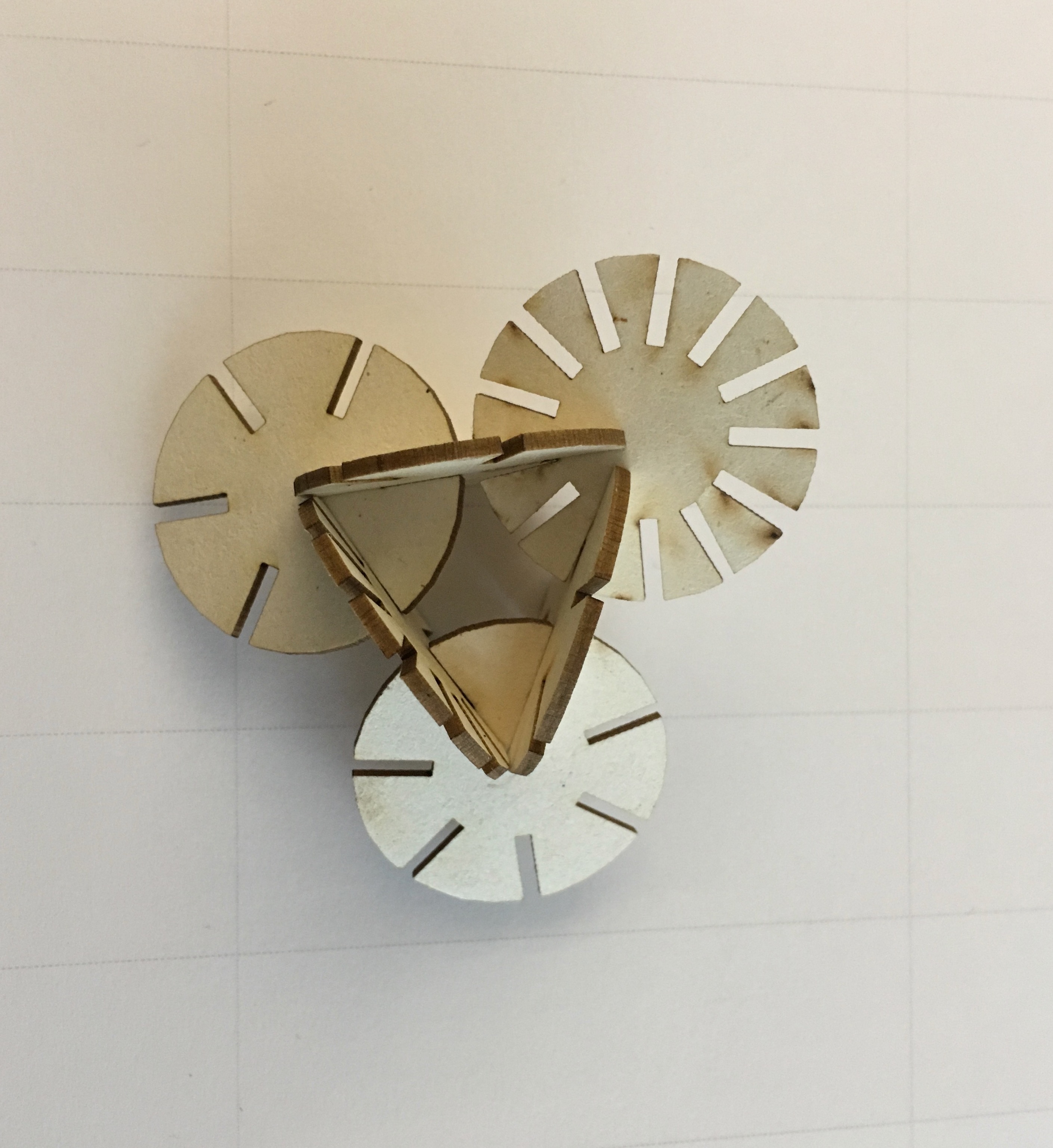
In order to use my OpenSCAD design, I used the same hack, as Paulina Previous year. In order to assure that the dimensions would be cut correctly: I had to open the .svg file and add "mm" to both the width end height properties. This is hack was necessary because OpenSCAD does not use specific unit for size measurement (like meter), but this information is needed for the laser cutter input. Then I tested my design by cutting one piece (general VisiCut settings). However, it is the first step that is troublesome. I forgot about proportioning between my design(radius of circle and size of cuts) and real sizes of future model. So, they did not "match".
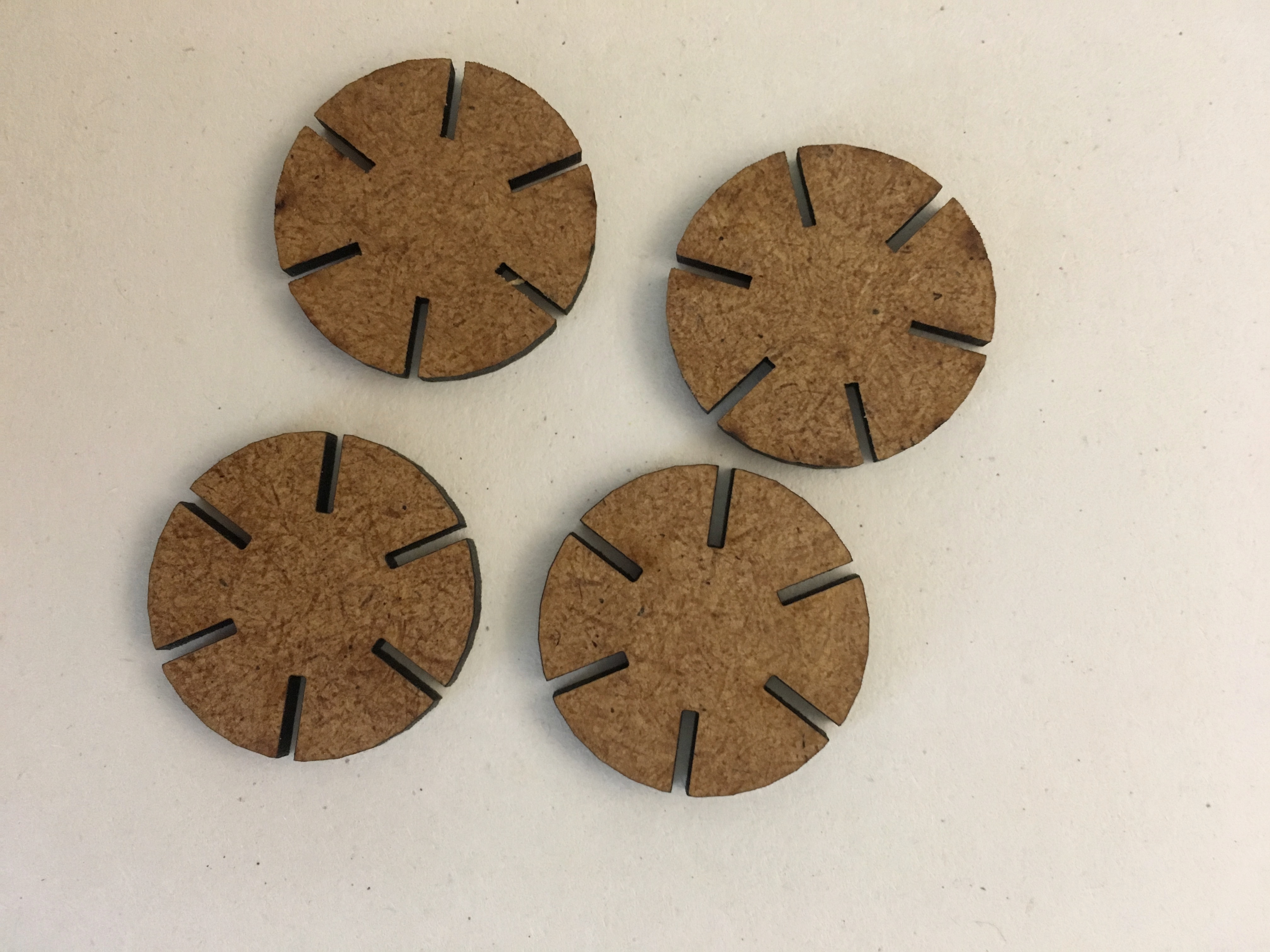
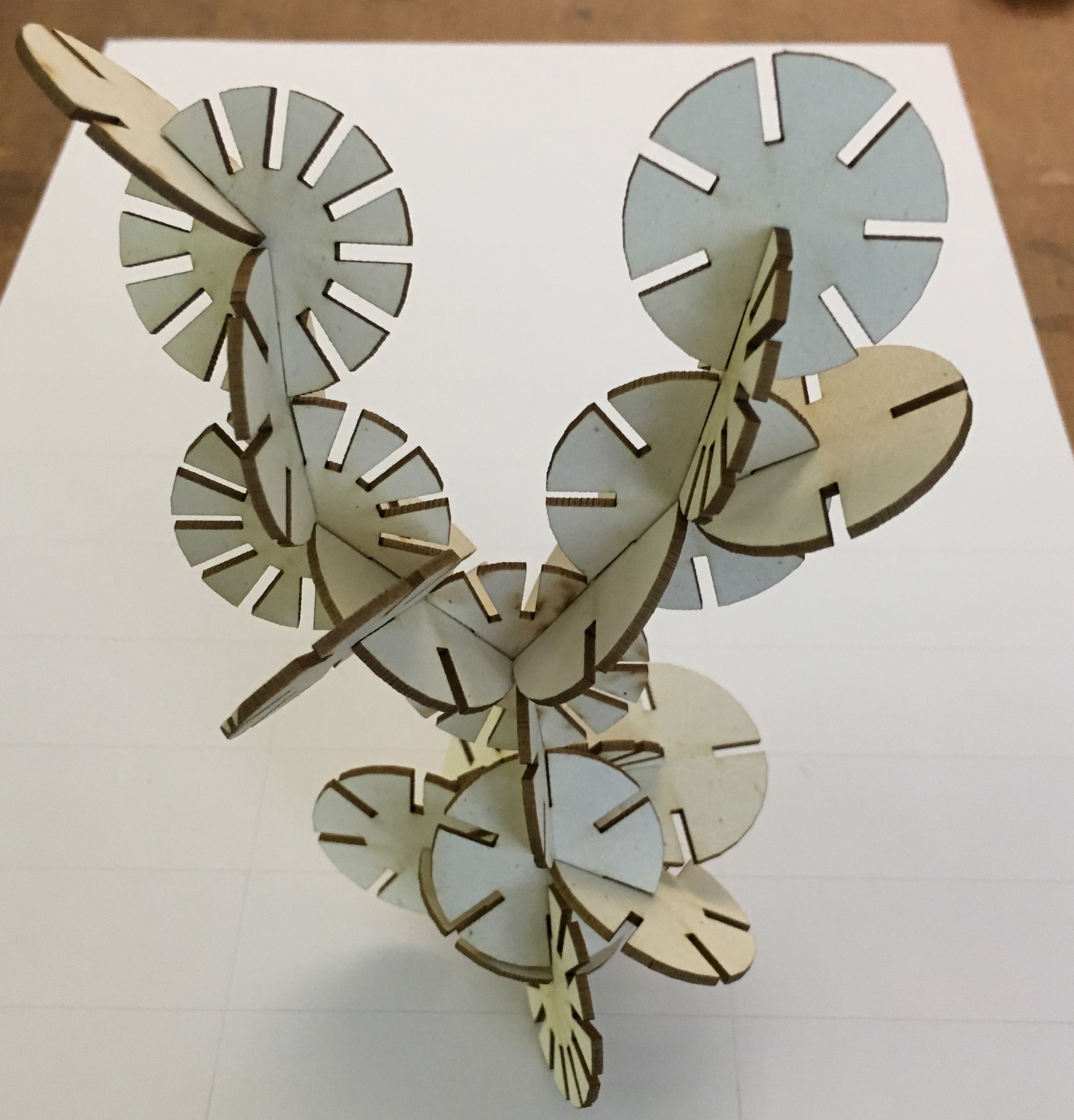
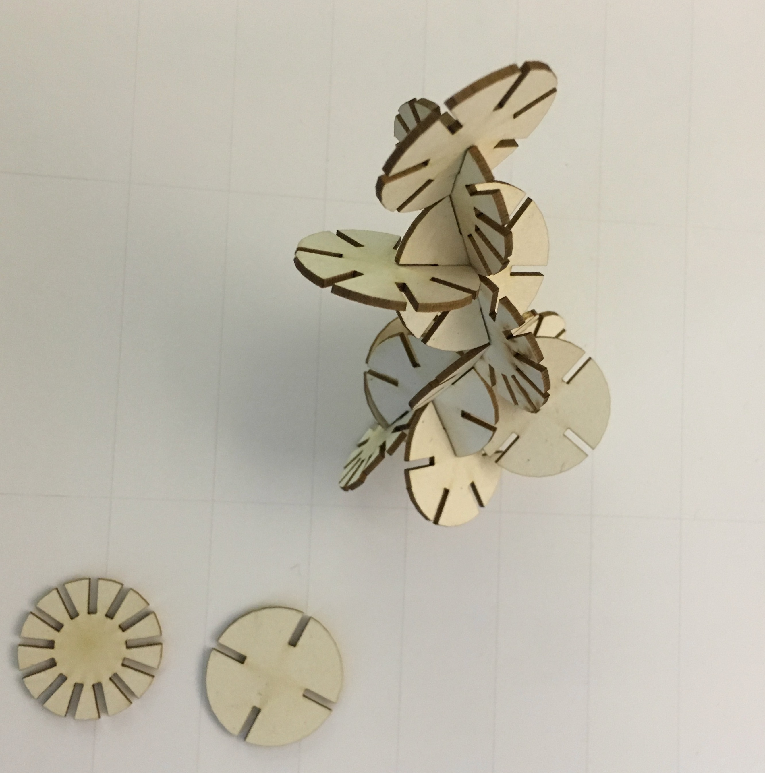
After correction of mistakes my pieces finally matched(hurrah!).
This is some kind of figure that I finally did. I like this design and I might use it as a jewelry chain holder.
Vinyl cutter
Getting to know the Vinyl cutter
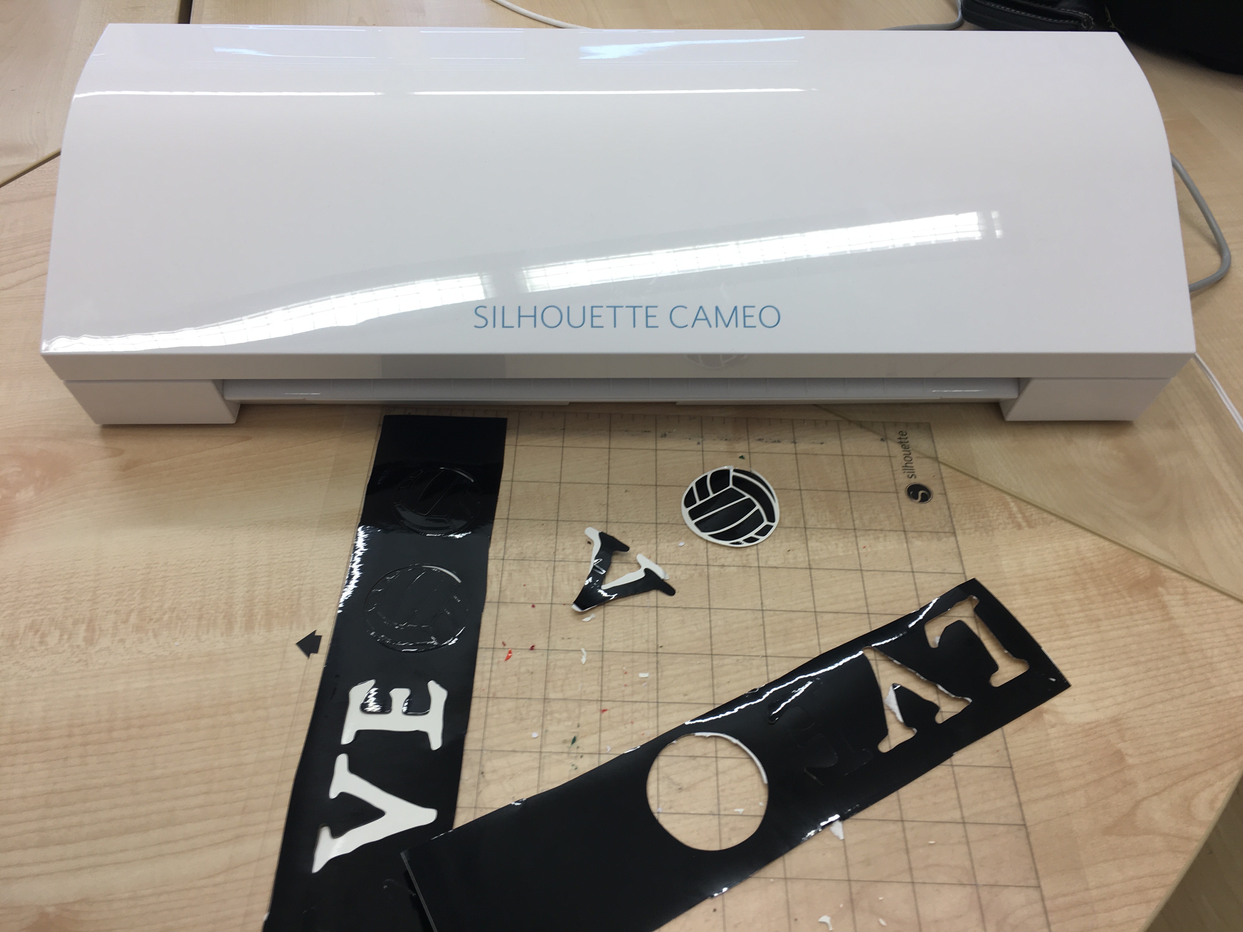
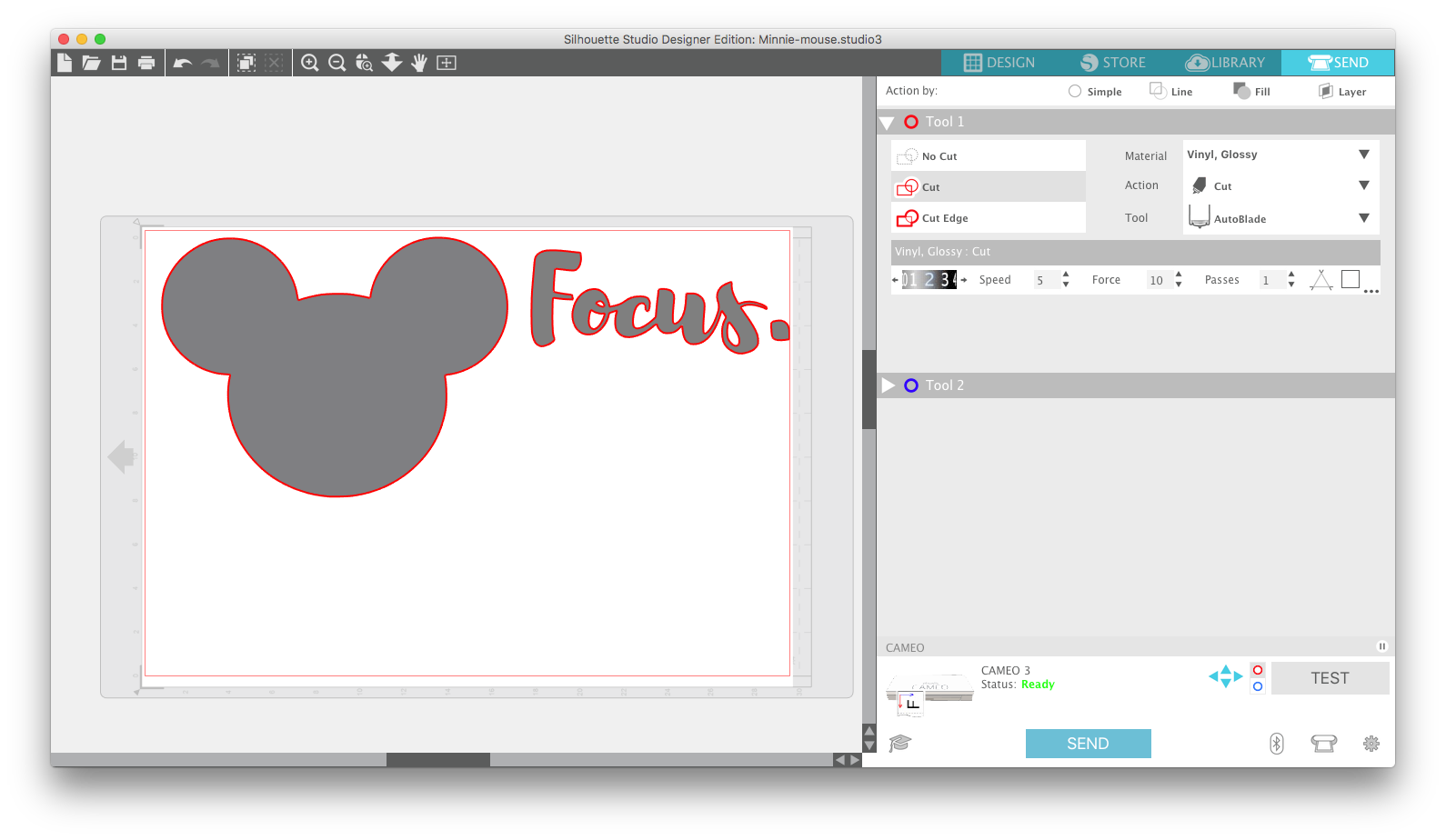
The machine that is at our disposal at FabLab Aachen is a Silhouette Cameo 3, which can be operated via bluetooth and by using the Silhouette Studio companion software.
Design the stickers
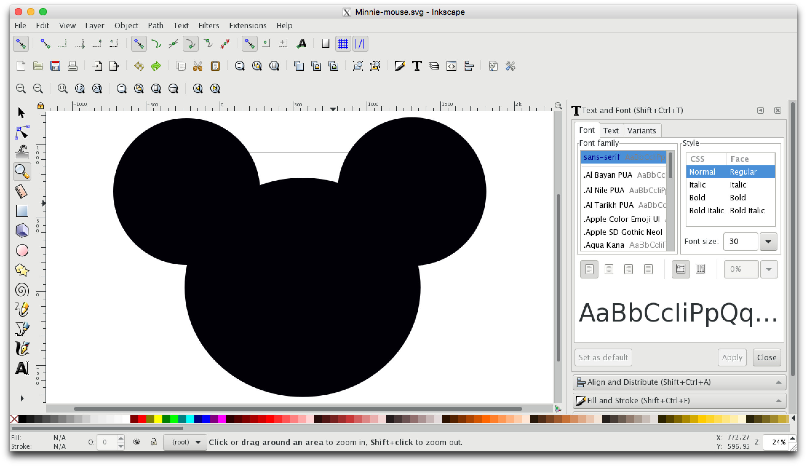
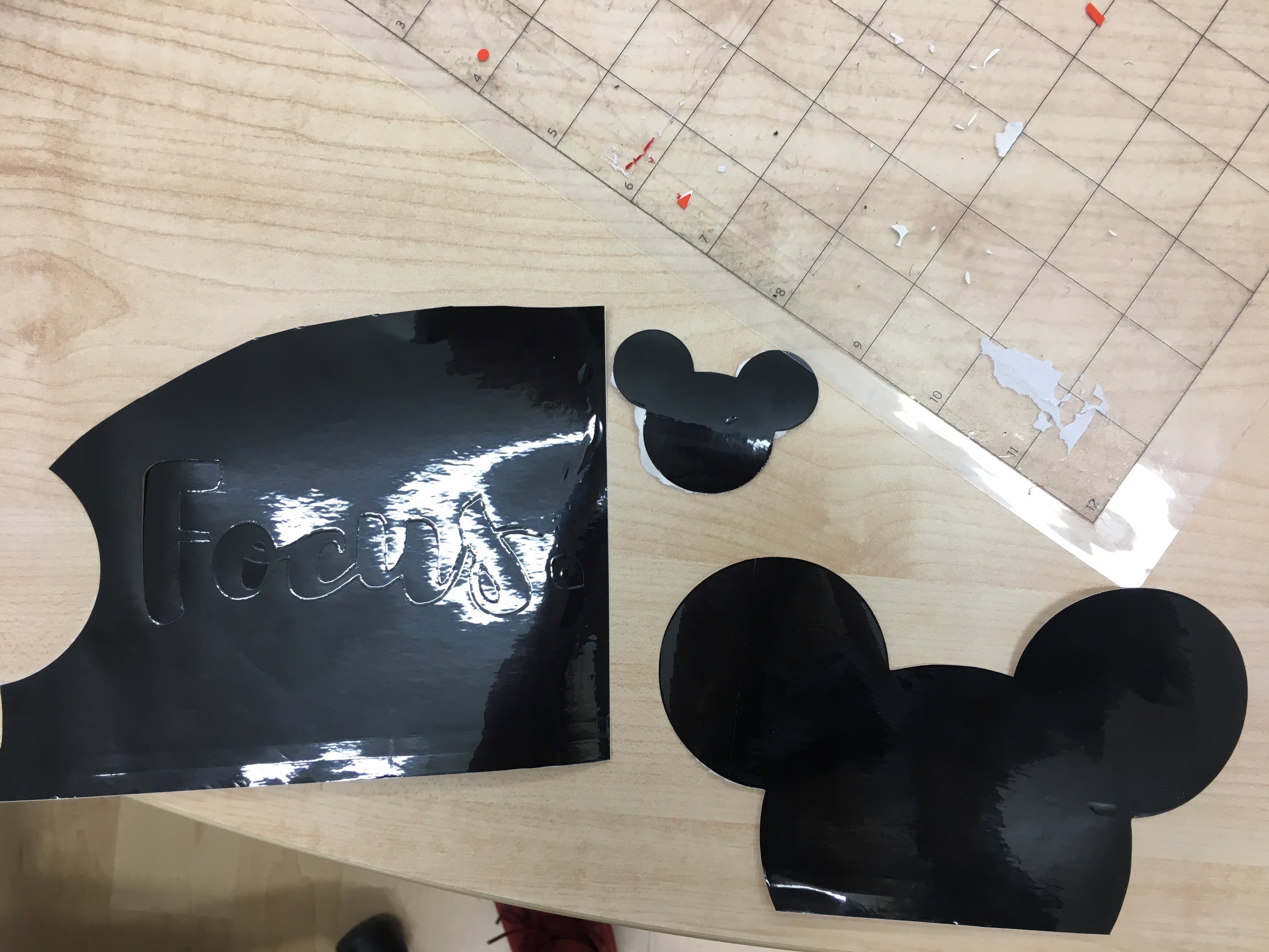
Since I haven't prepared design for the sticker to put on top of lid of my future Smart Planter and I still don't know the size of it, I decided to make a couple of laptop stickers. For getting an inspiration I used a pinterest.There I found sticker "Focus" and thought, that it is a nice idea to have some kind of "reminder", that might help me not to procrastinate in the Internet . I used downloaded before in this assignment font and made my design in Inscape. In order to be able to use the same design on other computer, I changed my letters to "curves":
I also thought that I really want to have a piece of Disneyland with me. So, I made a simple three circle design, which became to be a Mickey Mouse shape.
Using vinyl cutter
Let's start with overview of the step I managed to make stickers:
- First connect to the vinyl cutter by turning it on, turning on Bluetooth on your computer and connecting to it.
- Realise, that Bluetooth connection does not work :(
- Connect Anke's laptop and be happy, that you changed from font to path, otherwise you will miss the owesome font :)
- Then open Silhouette Studio, set your design page settings and and import your designs on it.
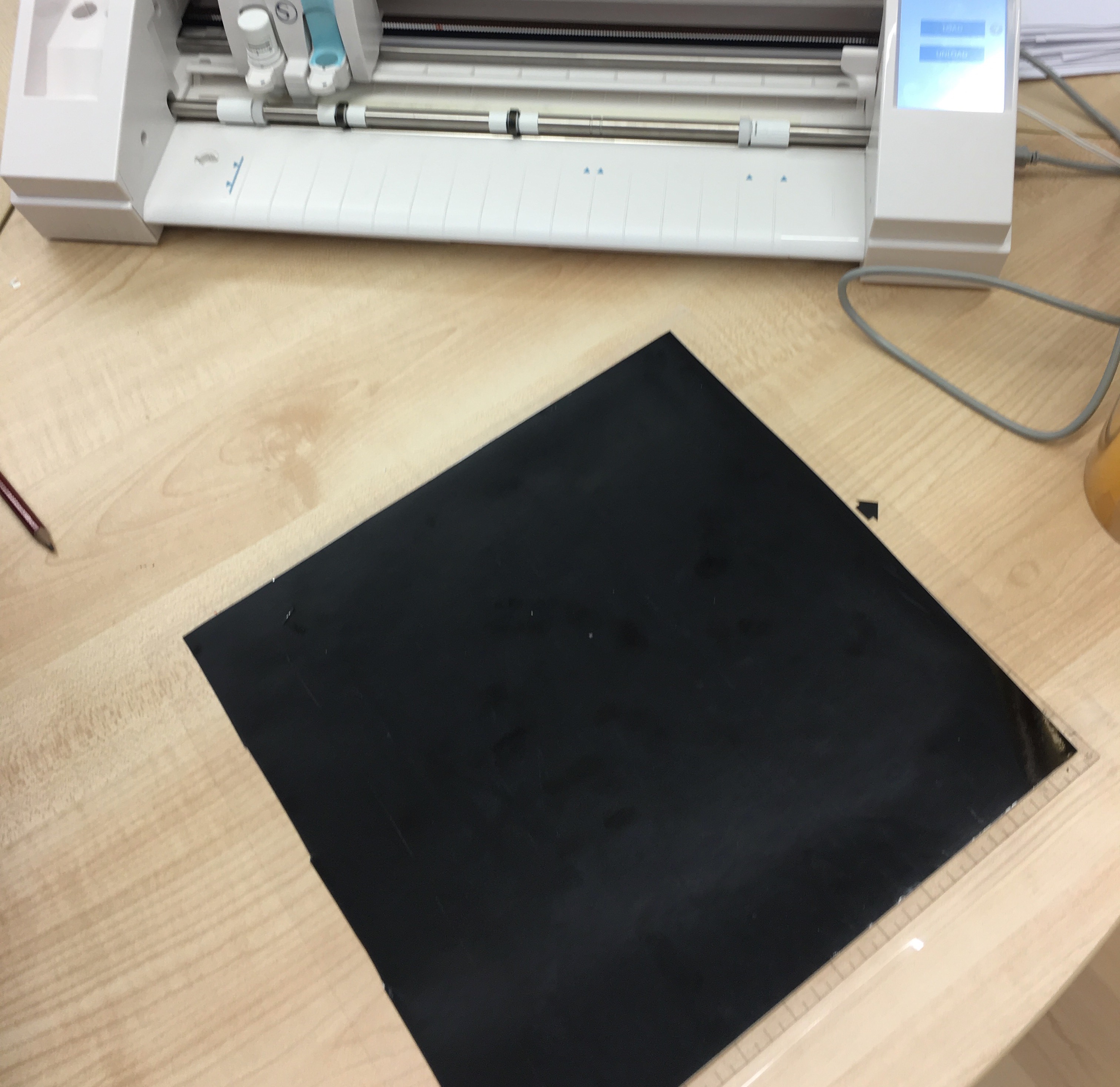
- Prepare the material by putting it onto the (sticky) cutting sheet.
- Place the sheet onto the markings of the laser cutter and select "load" from the touch screen. The machine will draw the sheet in a couple of centimeters in preparation of the cutting step.
- Now we can go back to the application and click "Send to Silhouette".
P.S. The mapping mistake was solved by general solution : turning off and on the printer.
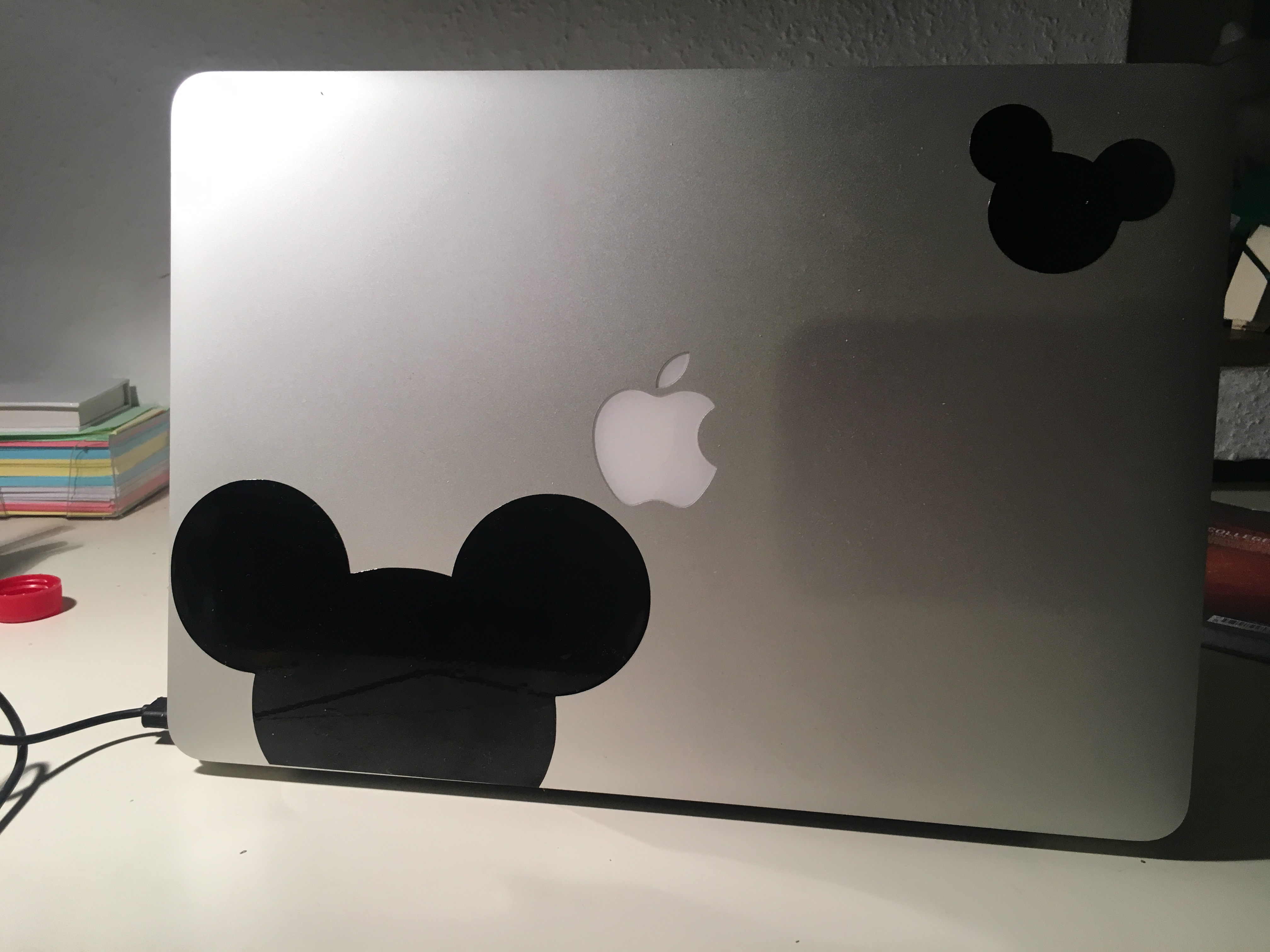
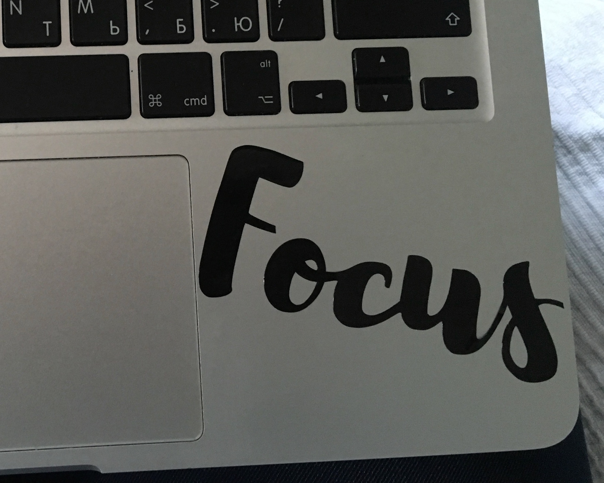
So, that is my final result:
Files
Download vector image of "Focus" as curves
.svg)
Download vector image of Minnie-mouse