Group Task
Mechanical and Machine Design
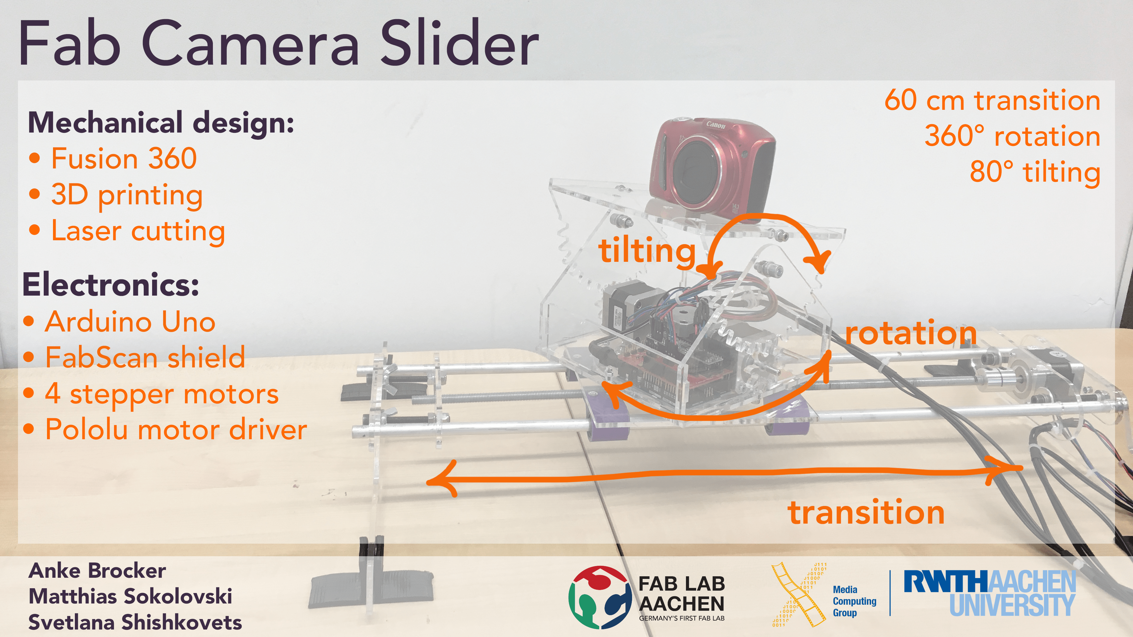
Result
Idea and Design
For this week our group planned to build a
camera slider for time-lapse photography.
In addition to the sliding axis we added two rotation axis for panning and tilting.
We distributed our roles: Svetlana did brainstorming for the layout of the machine, did the design of connectors and 3D printed them,
Matthias did the design of the camera stand and laser cut it,
Anke did the electronics and programming.
At the end we connected all the parts together.
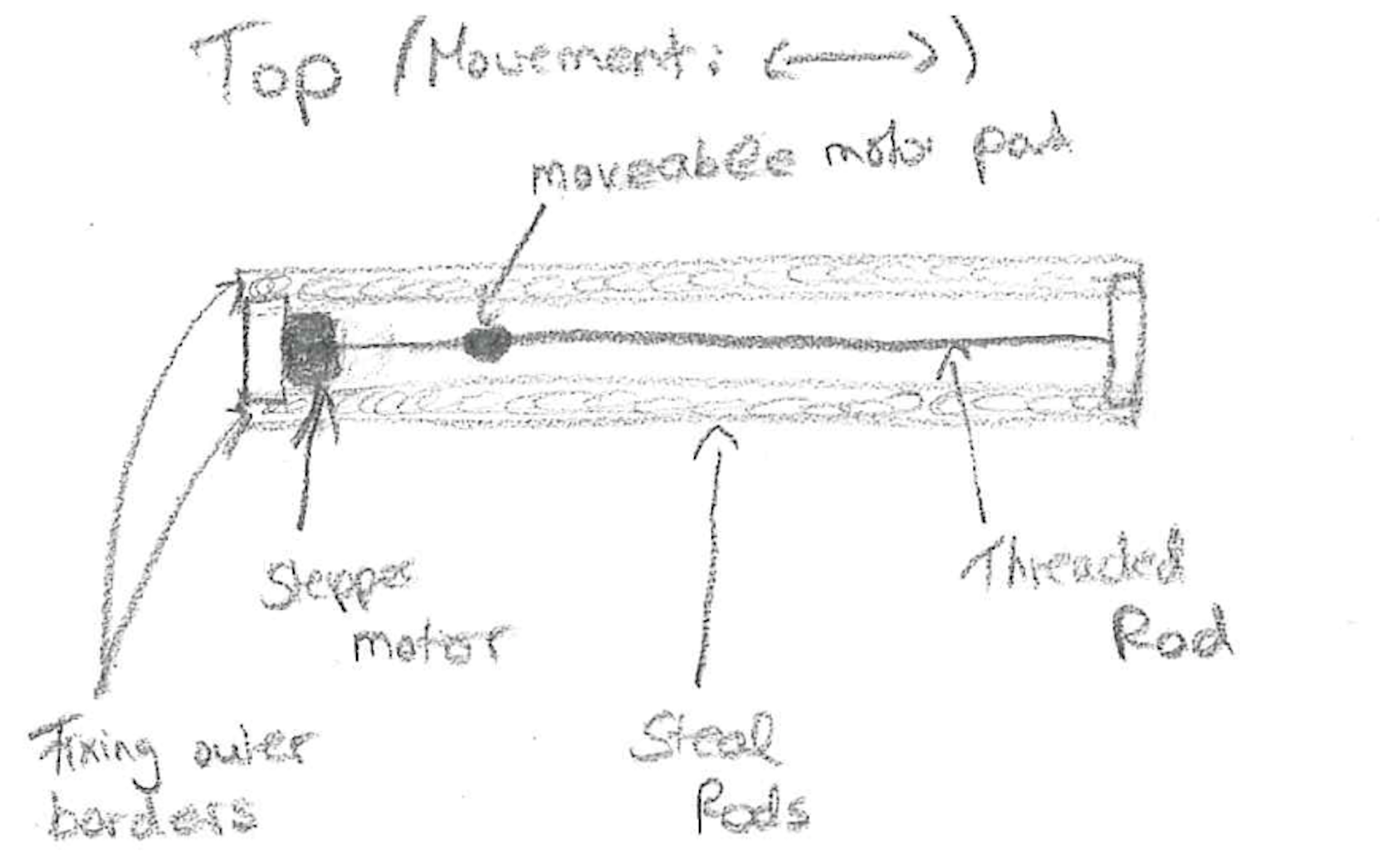
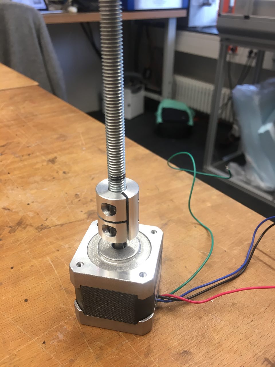
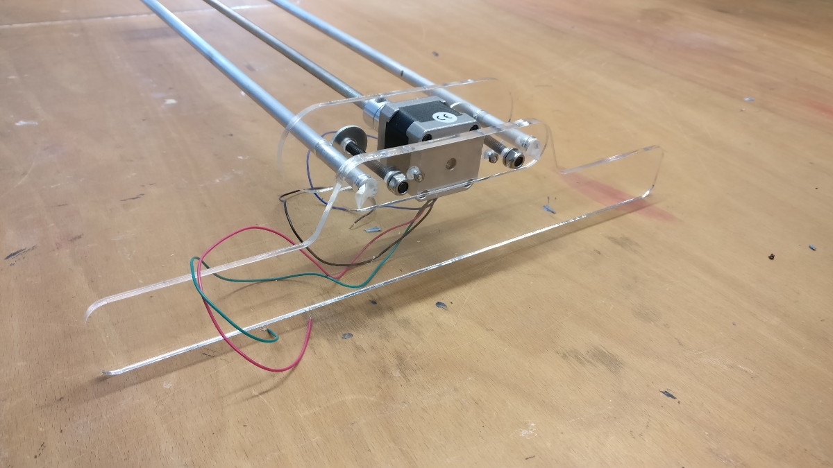
From the lab we use aluminum tubes that we will use as linear rails and are 62cm long. The slider is moved through a threaded rod attached to a stepper motor.
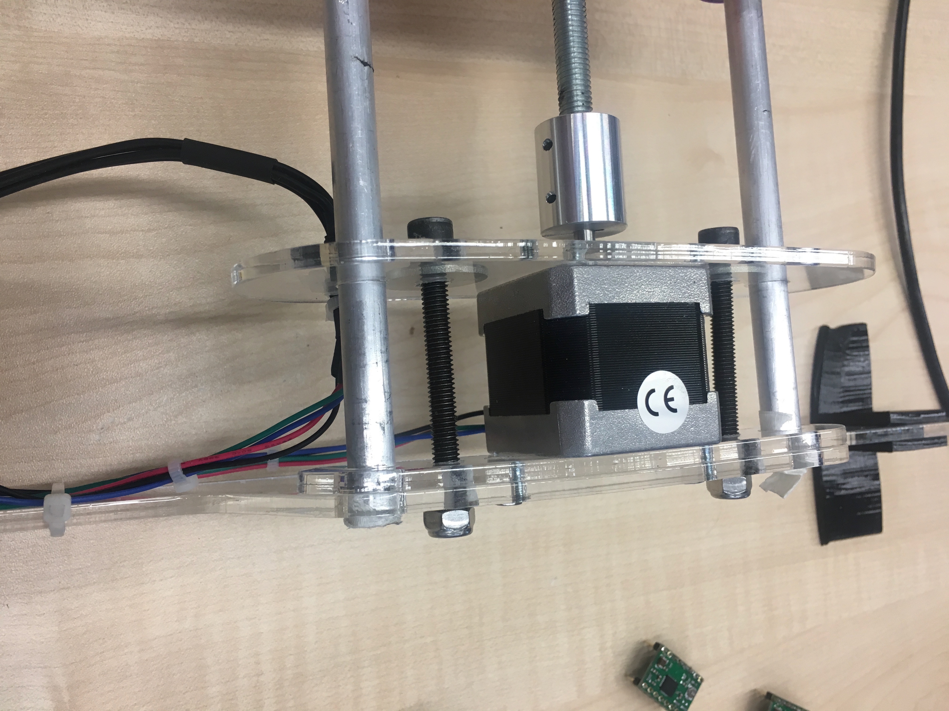
Camera head
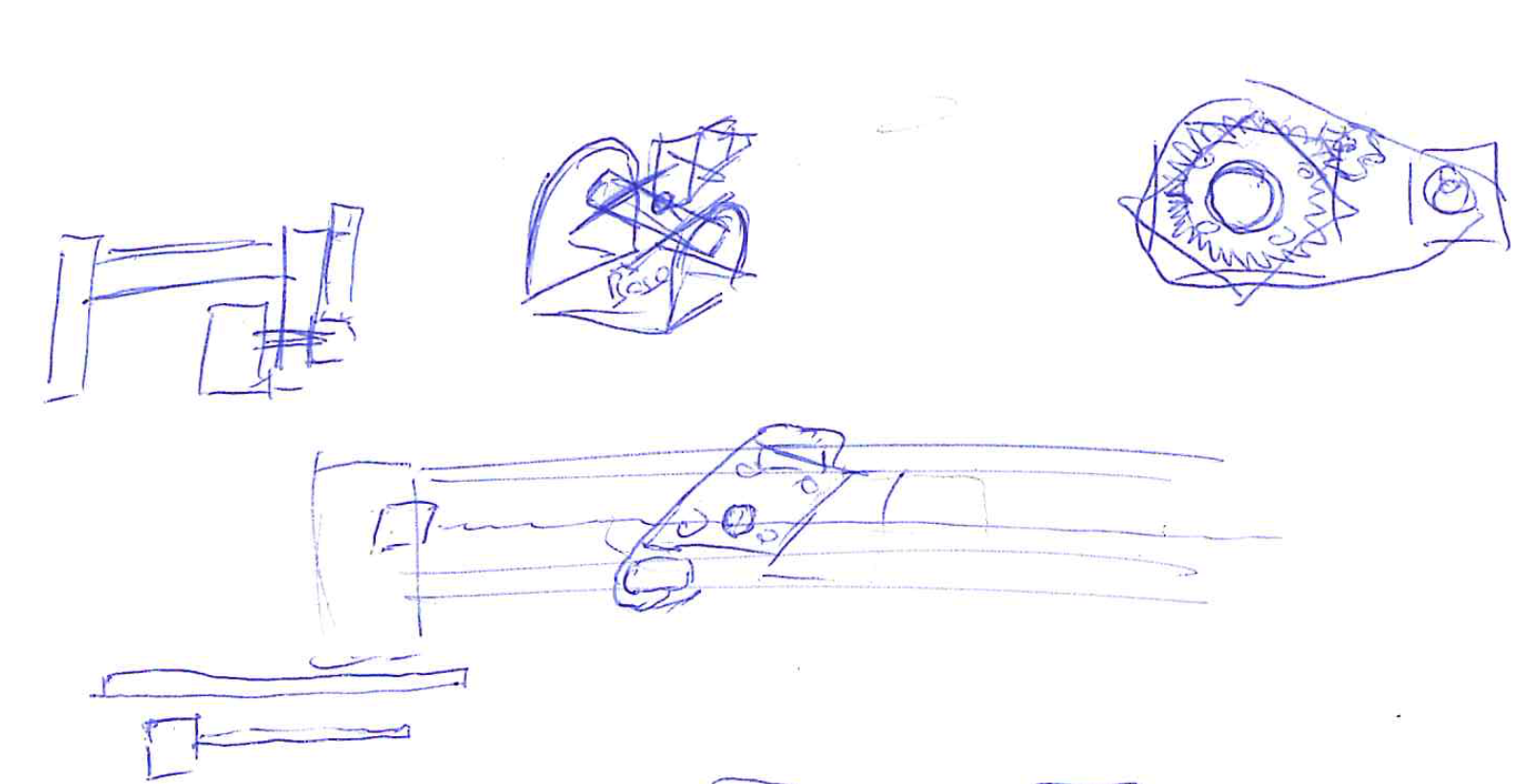
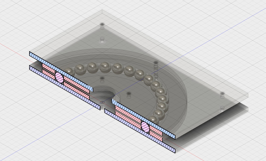
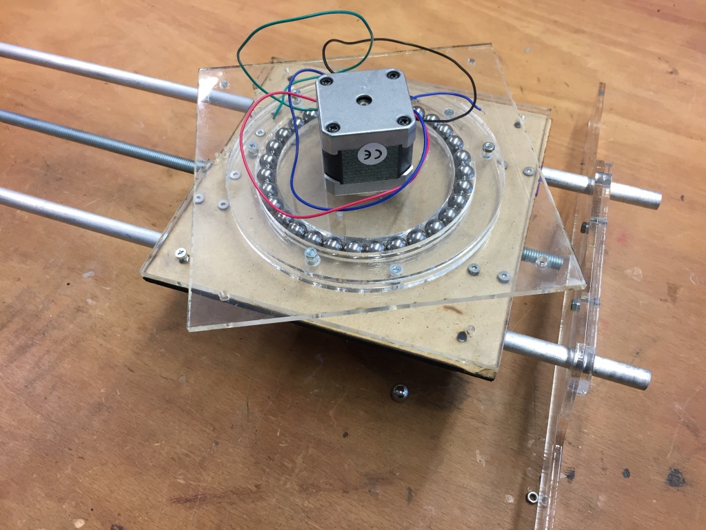
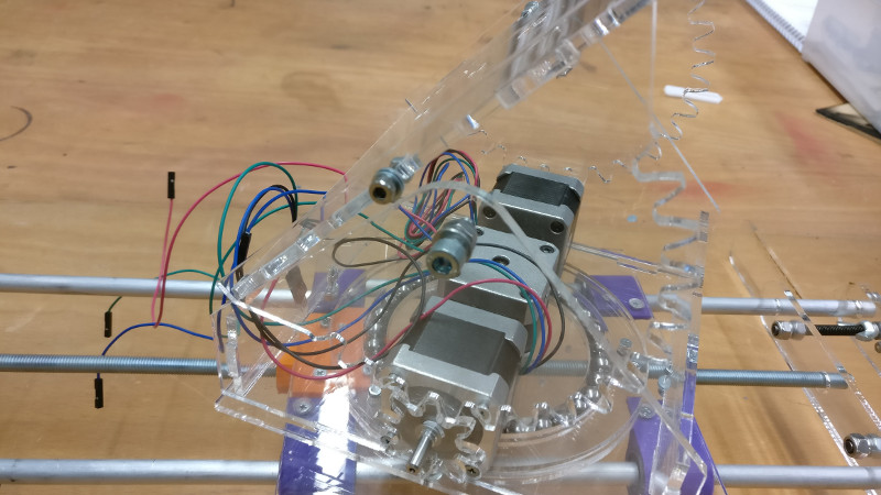
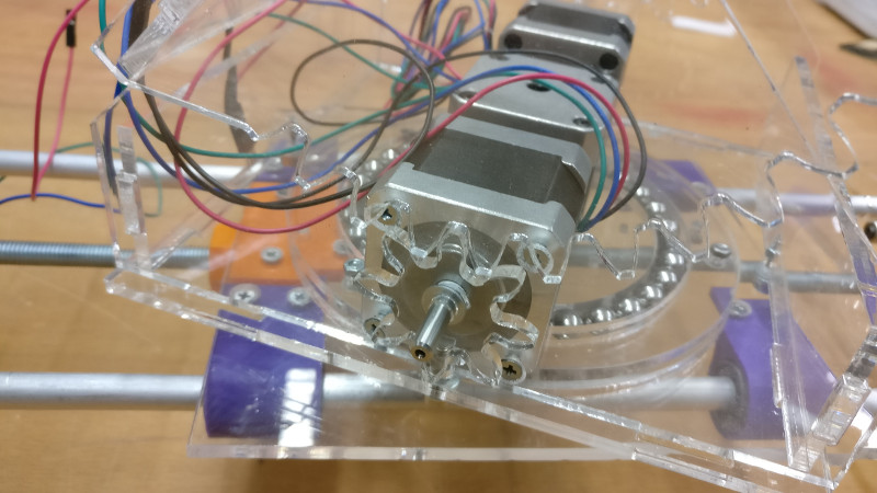
For the pan rotation assembly we decided to construct a large custom bearing with a stepper motor in the center.
This was constructed from four acrylic circles (red shading) creating a cavity for steel balls (purple shading).
Ultimately, the load is placed on the balls as there is a spacing between the acrylic plates allowing a smooth, frictionless rotation.
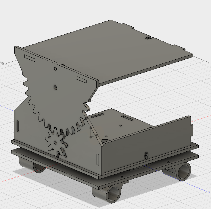
The tilt axis is the most complicated one.
Essentially, we build a large hinged platform with a gear-teeth on one plate.
Through another gear that is attached to a stepper motor the entire assembly can be operated.
For symmetry reasons, stability and force distribution we used a motor on both sides.
Partlist
- 4mm acrylic, 6 sheets of 60x30cm or equivalent
- 3D printing material, stiff and flexible (e.g. PLA and TPU)
- 4x LM12UU linear bearings
- 2x steel rods, 12mm diameter
- 1x M10 threaded rod
- 2x M10 nuts
- 30x steel balls 10mm diameter (buy more, you will lose some)
- 3x NEMA17 stepper motors
- 3x Polulu stepper drivers
- 1x FabScanShield
- 1x Arduino uno
- 1x 12V power supply with barrel jack
- 38x M3 screw and nut
Manufacturing
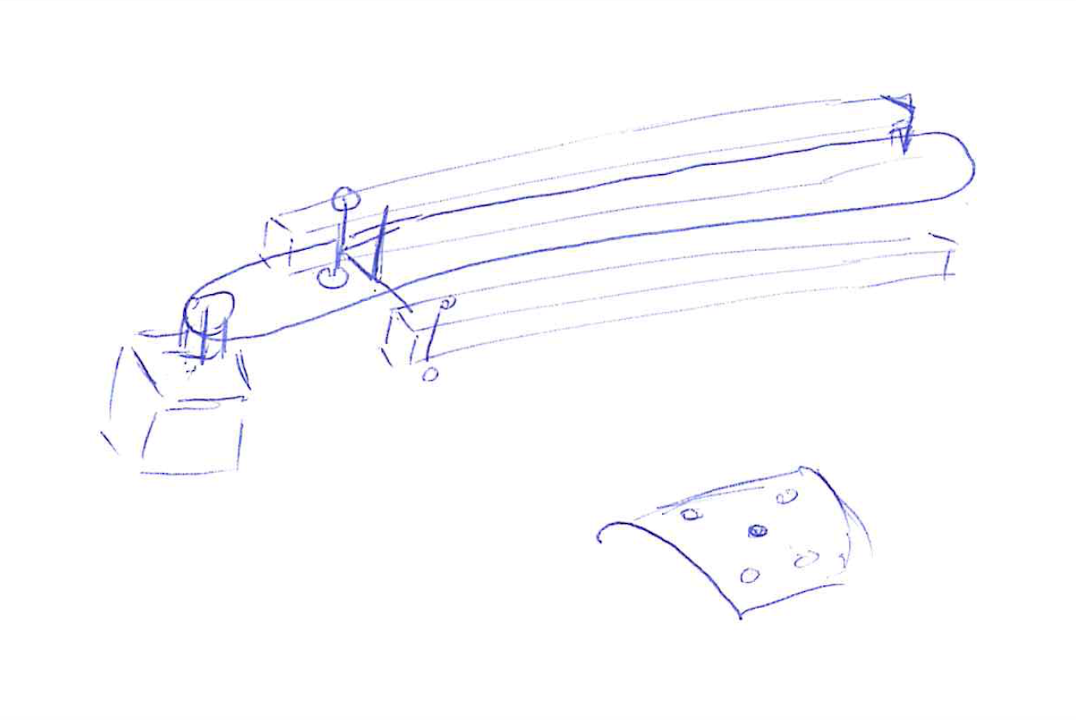
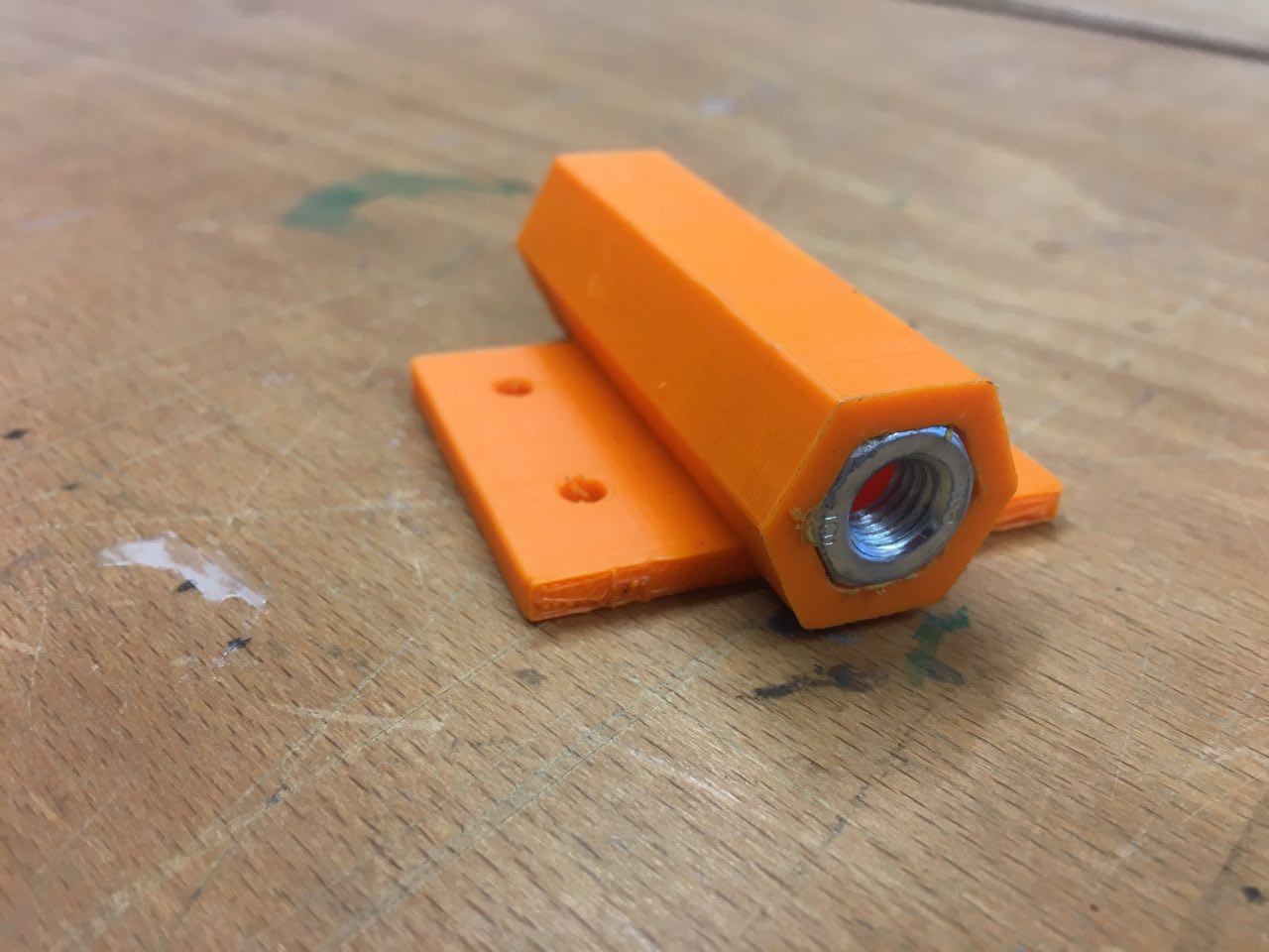
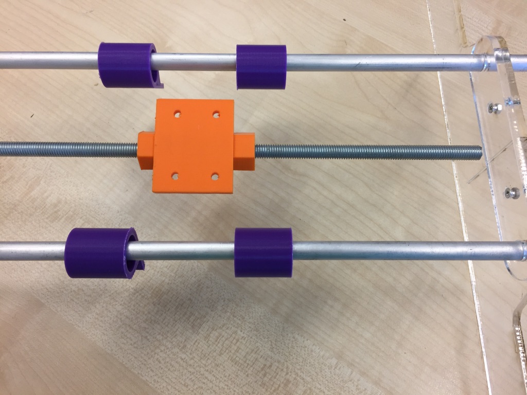
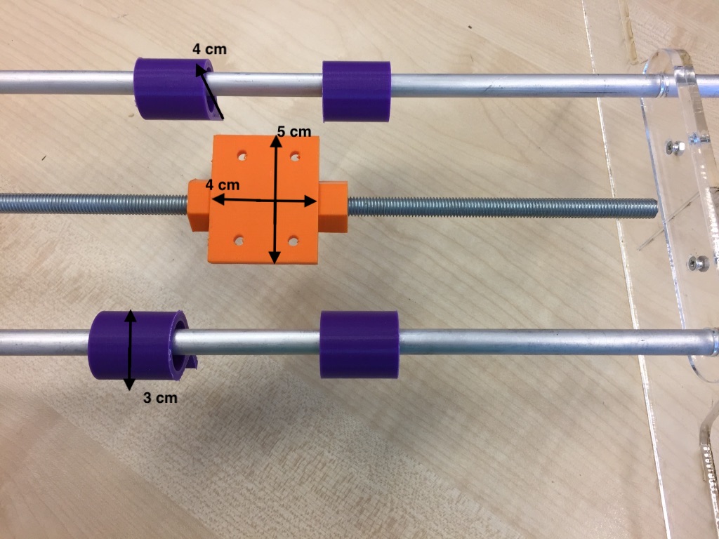
We designed orange part as a big platform to connect the threaded rod to the camera head, so it will move while motor will rotate the rod. For that we putted the nut inside.
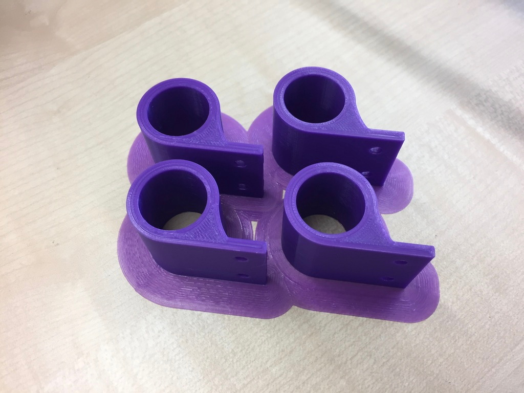
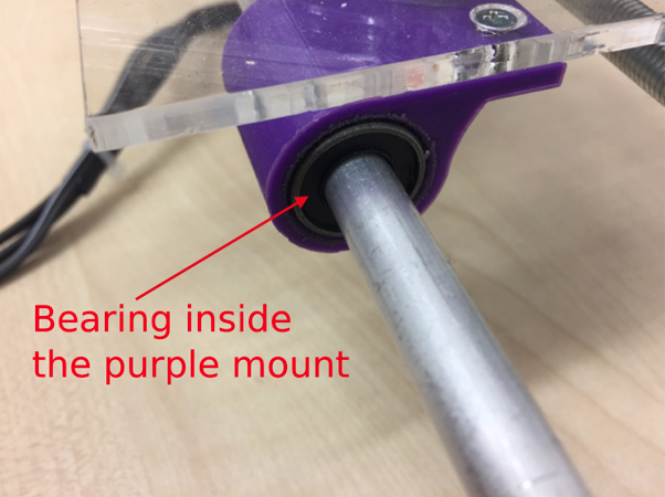
We also designed the purple parts in order to connect the heavy stand + camera steady to the construction. We added bearings to avoid friction problem.
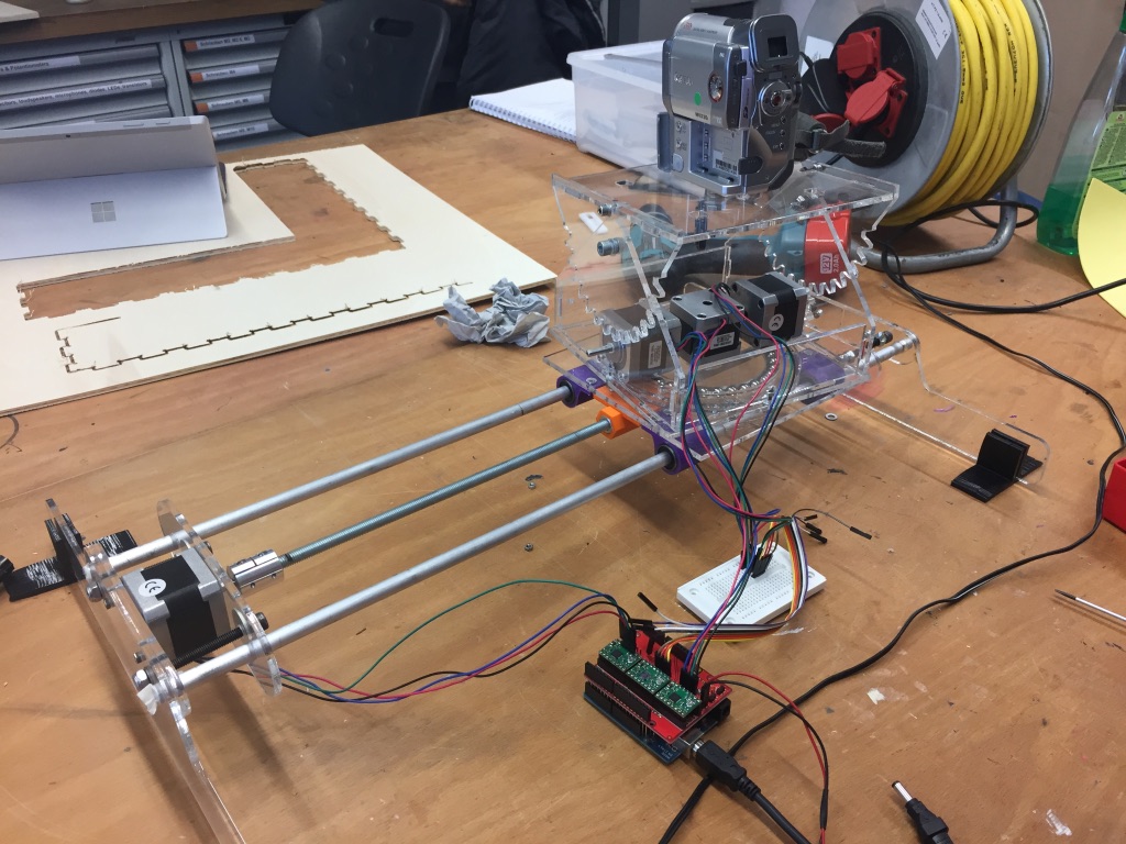
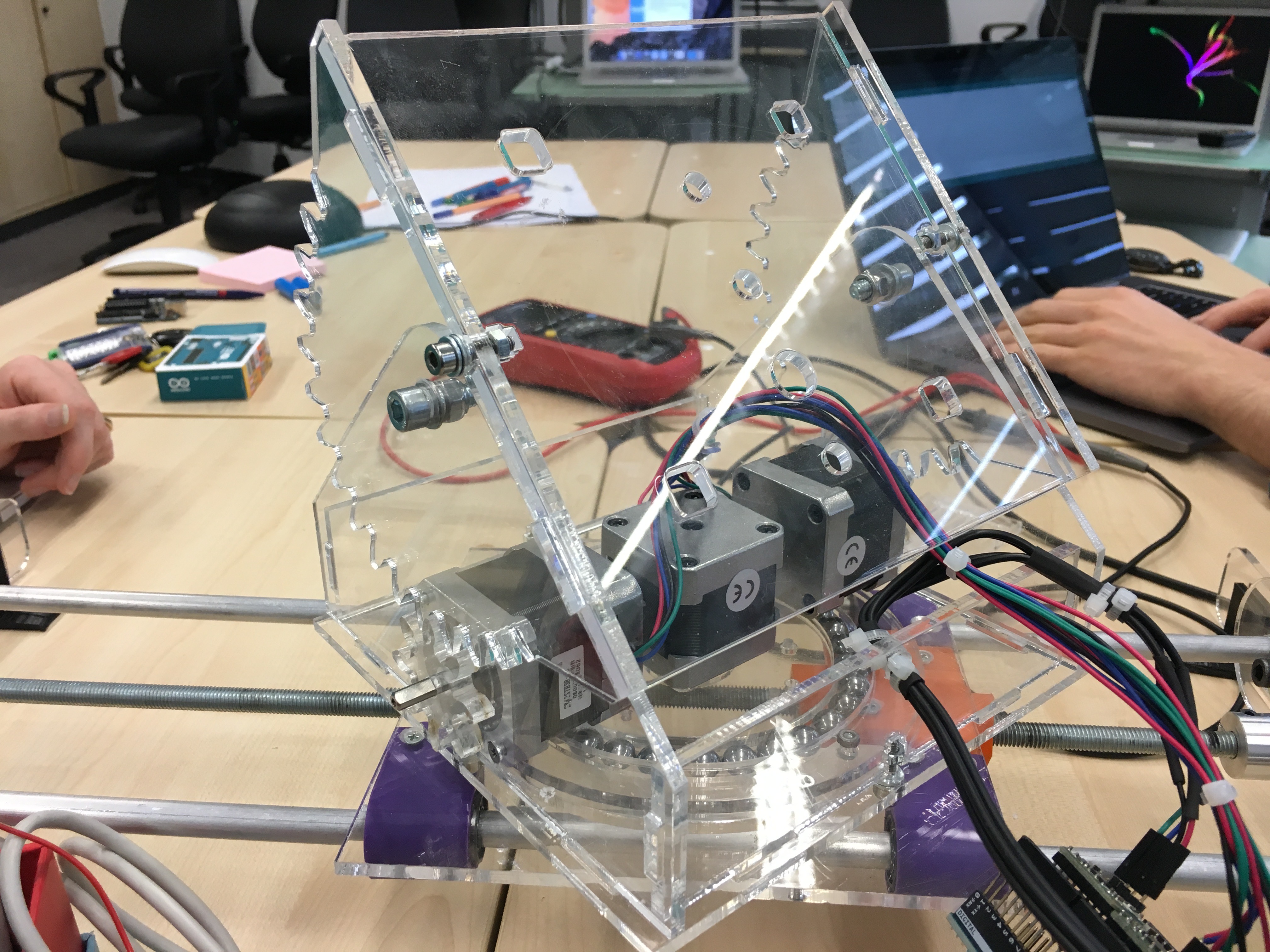
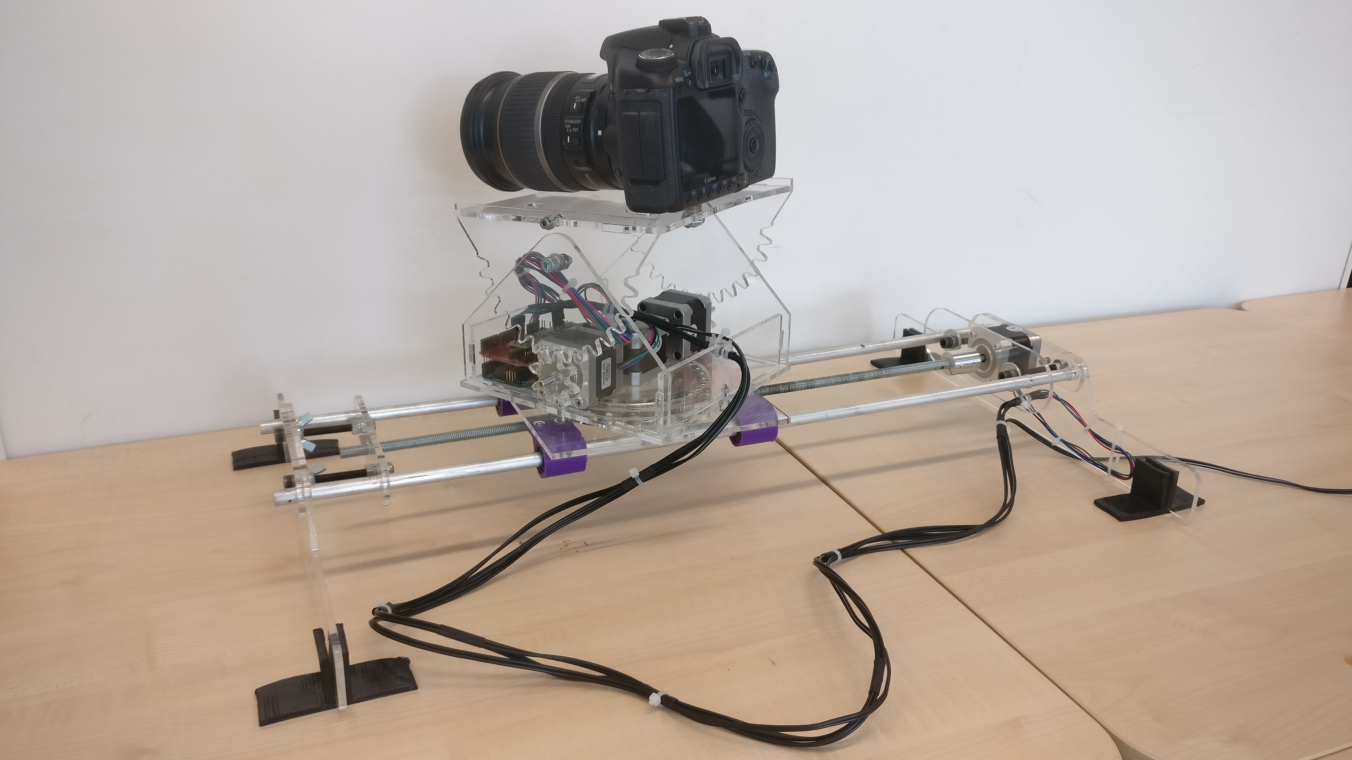
So, that is how our super steady construction looks like:
First, we decided to attach the linear bearing holders and the orange object to an MDF tile. This way the threaded rod and the aluminium tubes are connected and when the stepper motor starts working the MDF tile is moved along the threaded rod.
In the end we removed the MDF and attached the these parts directly to the bottom plate of our large bearing just to avoid an additional piece. However, for a first prototype the MDF part worked perfect, but maybe a bit ugly.
All other parts were manufactured on the LaserCutter from 4mm acrylic.
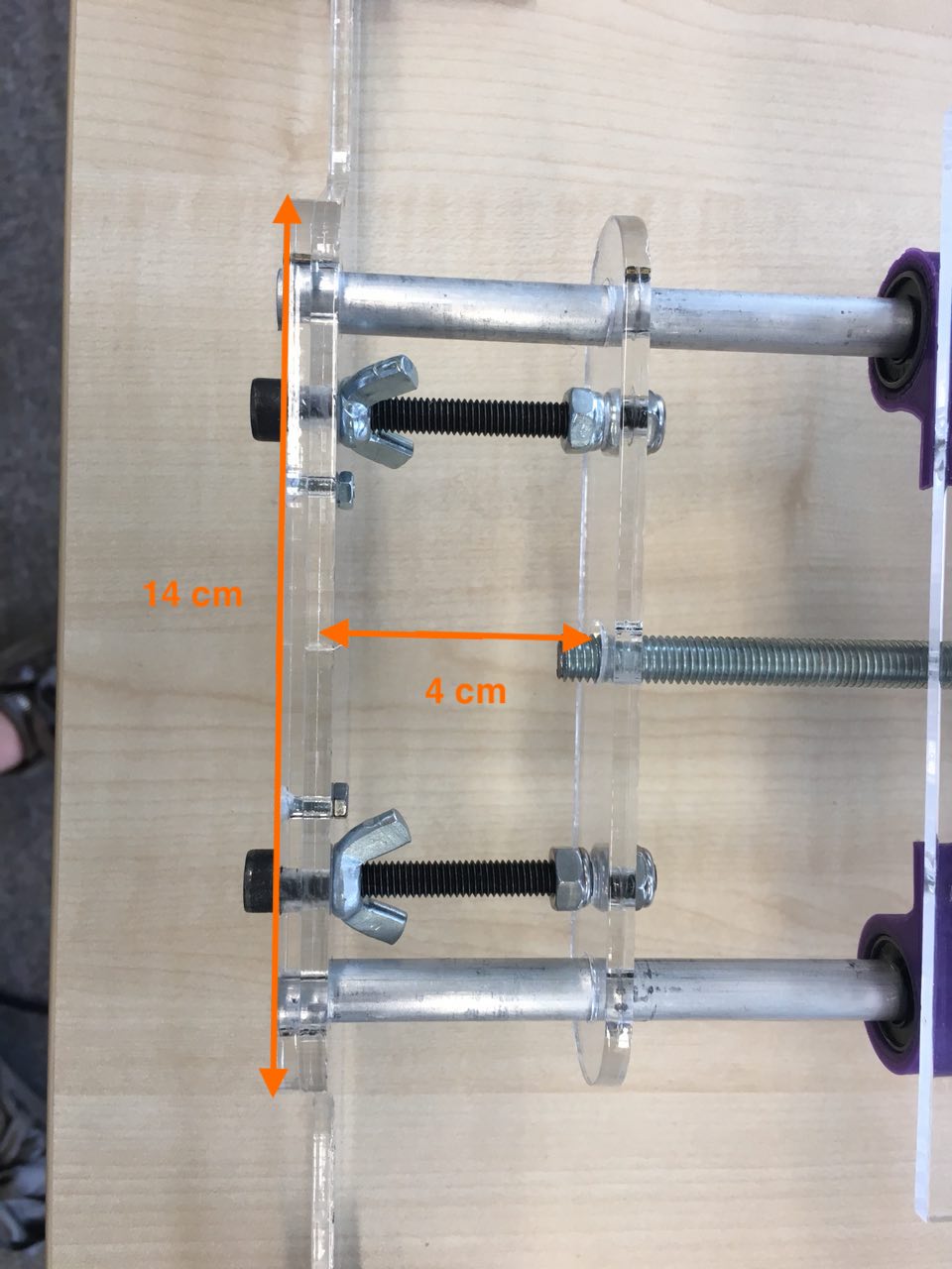
The stands are the largest parts.
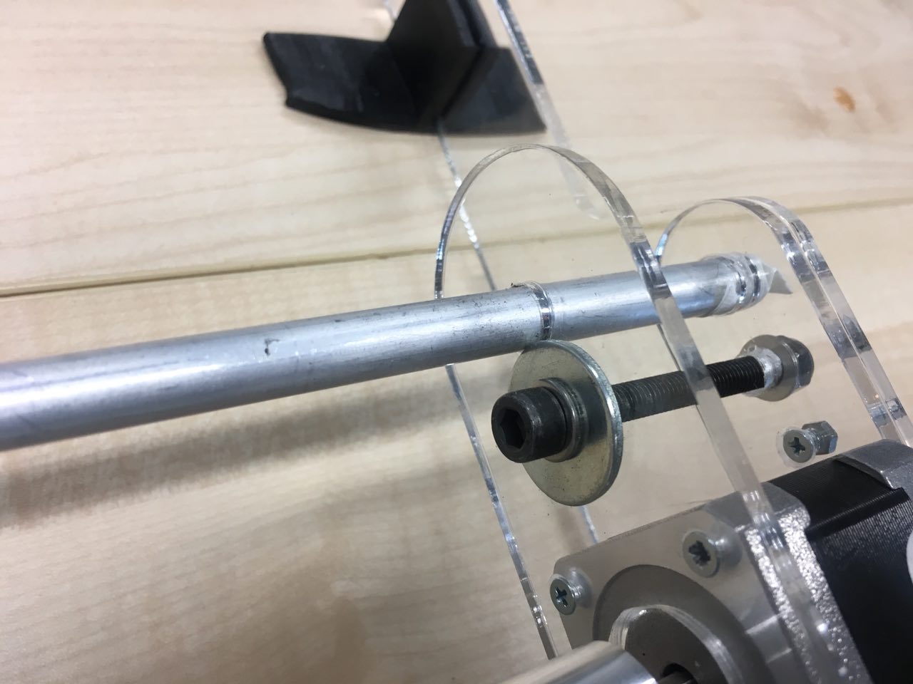
In order to hold the aluminum tubes safely we reinforced this area with a second plate.
This added much stability to the axis assembly.
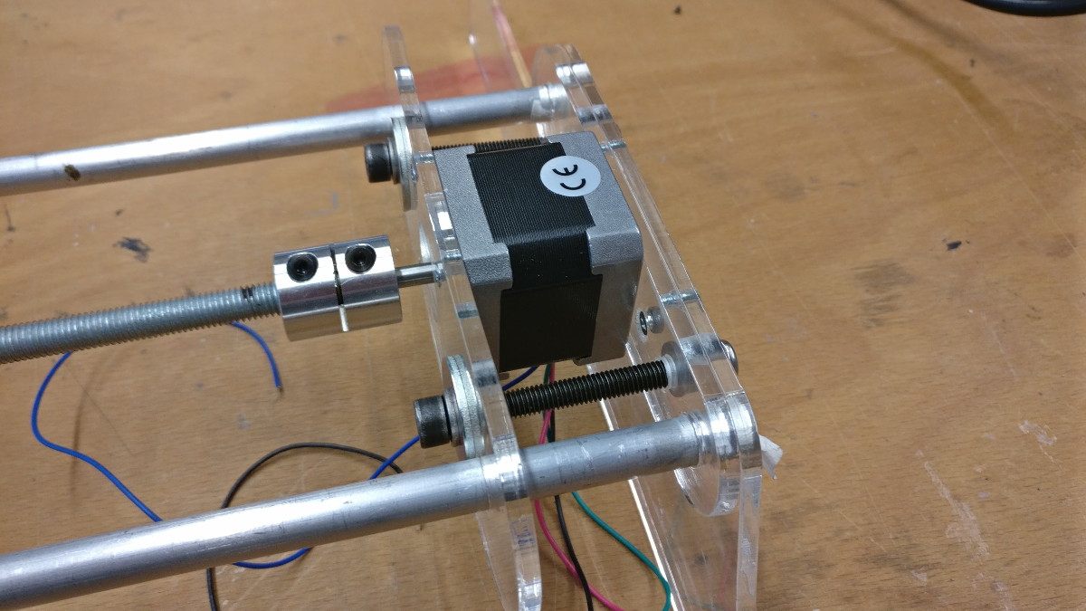
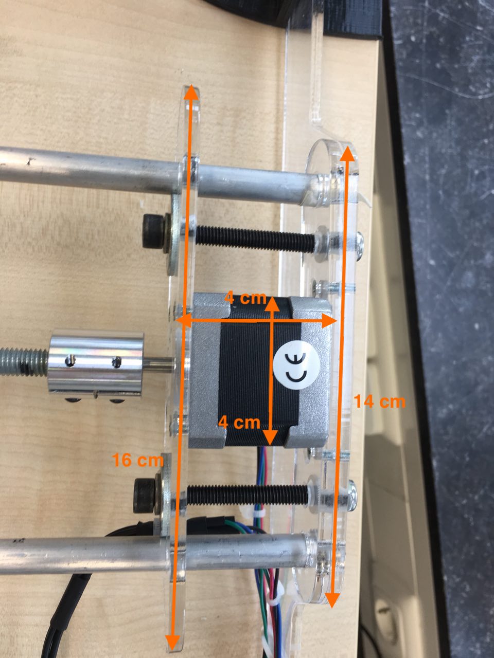
The motor was mounted on an additional plate attaching it to the tube assembly in a similar fasion.
The hole sandwich is hold together with 2 long M6 bolts.
In order to reduce punctual forces on the acrylic and avoid cracking it we used large washers on the bolts.
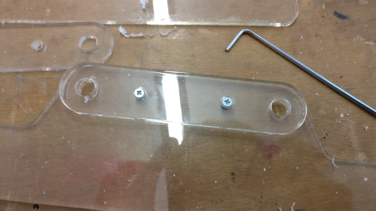
Where ever else we had to connect two pieces of acrylic we used countersunk M3 screws.
Using a counter sink drill bit to enlarge the holes on one side allows them to sit flush in the acrylic.
They also screw directly into the NEMA 17 stepper motor making them the ideal universal fastener for the project.
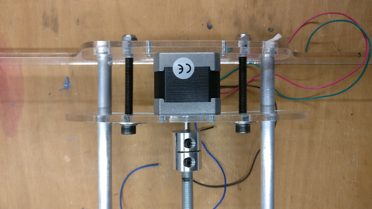
We chose acrylic as the material to work with as after assembling it is still
possible to see the mechanisms of the machine (e.g. the thrust bearing).
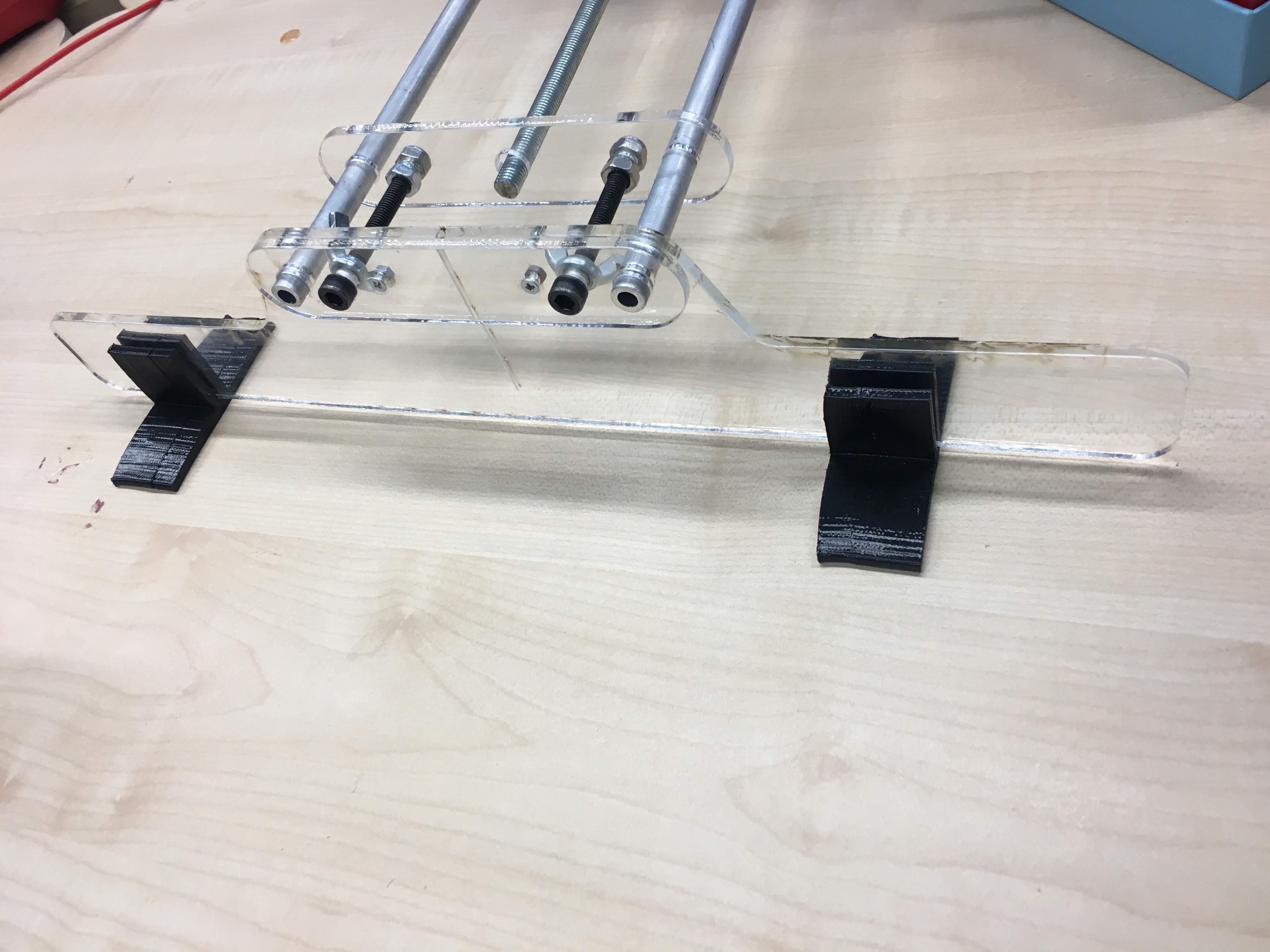
3D printed rubber feet
With roughly 30cm long feet we expected the stands to provide sufficient stability.
However, everything was still a bit slippery and not very convincing.
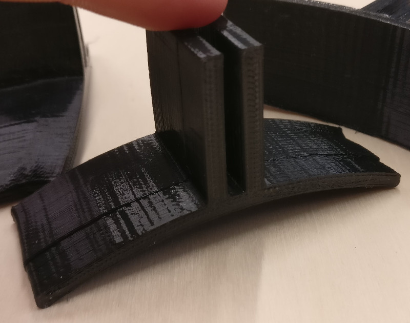
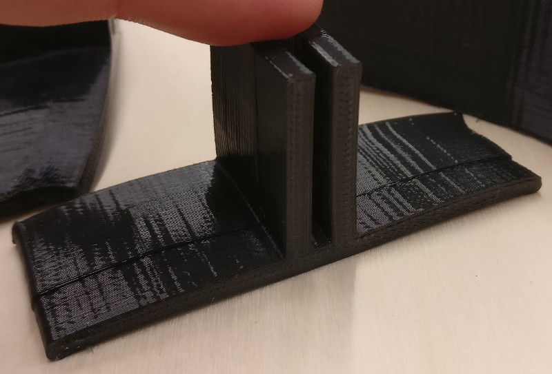
In a late design addition we constructed 4 rubber feet, that were 3D printed from flexible filament.
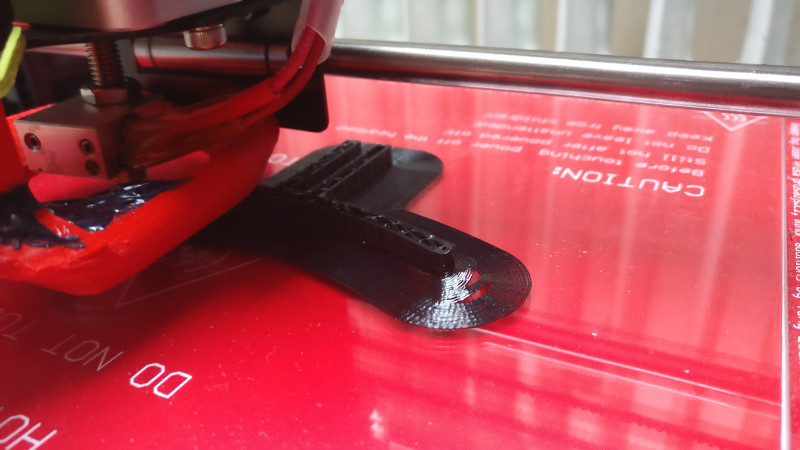
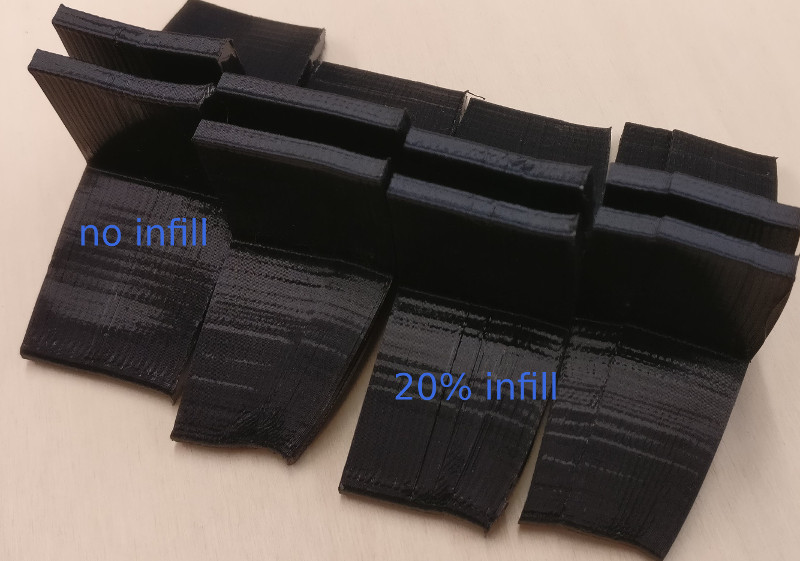
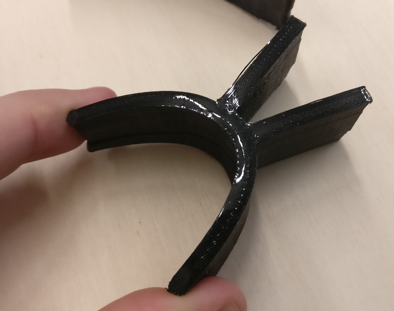
We had black flexible filament available at the Lab labeled with 'TPC Flex 45'.
Although a short online search provides different values, in our case this filament printed
well around 200°C on glass.
However, each attempt resulted in the print lifting from the buildplate due to inner material stress.
Build plate temperate seems to have no impact on adhesion, 60°C/70°C and no heating yielded equal results.
The only adjustment with impact was removing infill entirely.
This makes the part even more flexible and (for some reason) counteracts most lifting.
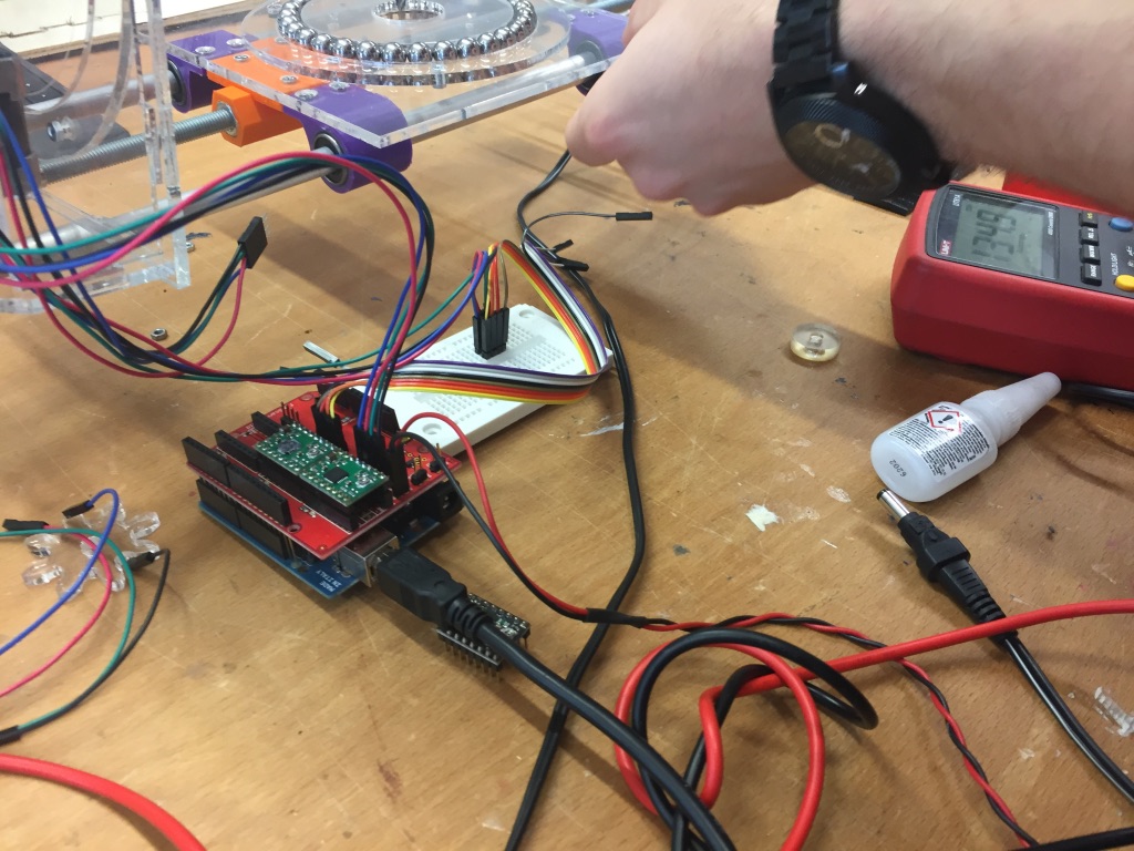
Motors and Electronics
To move our camera, rotate and tilt it we used
NEMA 17 stepper motors.
As stepper motors are non trivial to operate they require a special drive circuitry.
To operate our 4 stepper motors on 3 axis
we stacked several hardware components to a 3-layer PCB sandwich.
This is based on an arduino Uno,
the FabScan shield
and three
Pololu A4988 Stepper Motor Drivers.
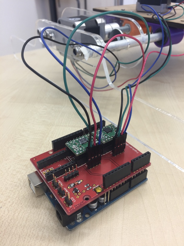
The A4988 operate the stepper motors and attach through the FabScan shield to the arduino.
The arduino calculates the correct motion sequence based on parameters set in the program (more on this later)
As for most group members using a step motor was a new topic we had a look for helpful tutorials.
We found the following two:
The FabScan shield exposes pin-headers for three motors (based on the three driver).
The cables for the tilt motors were crimped together into one pin-header.
This way they can be operated together by one driver.
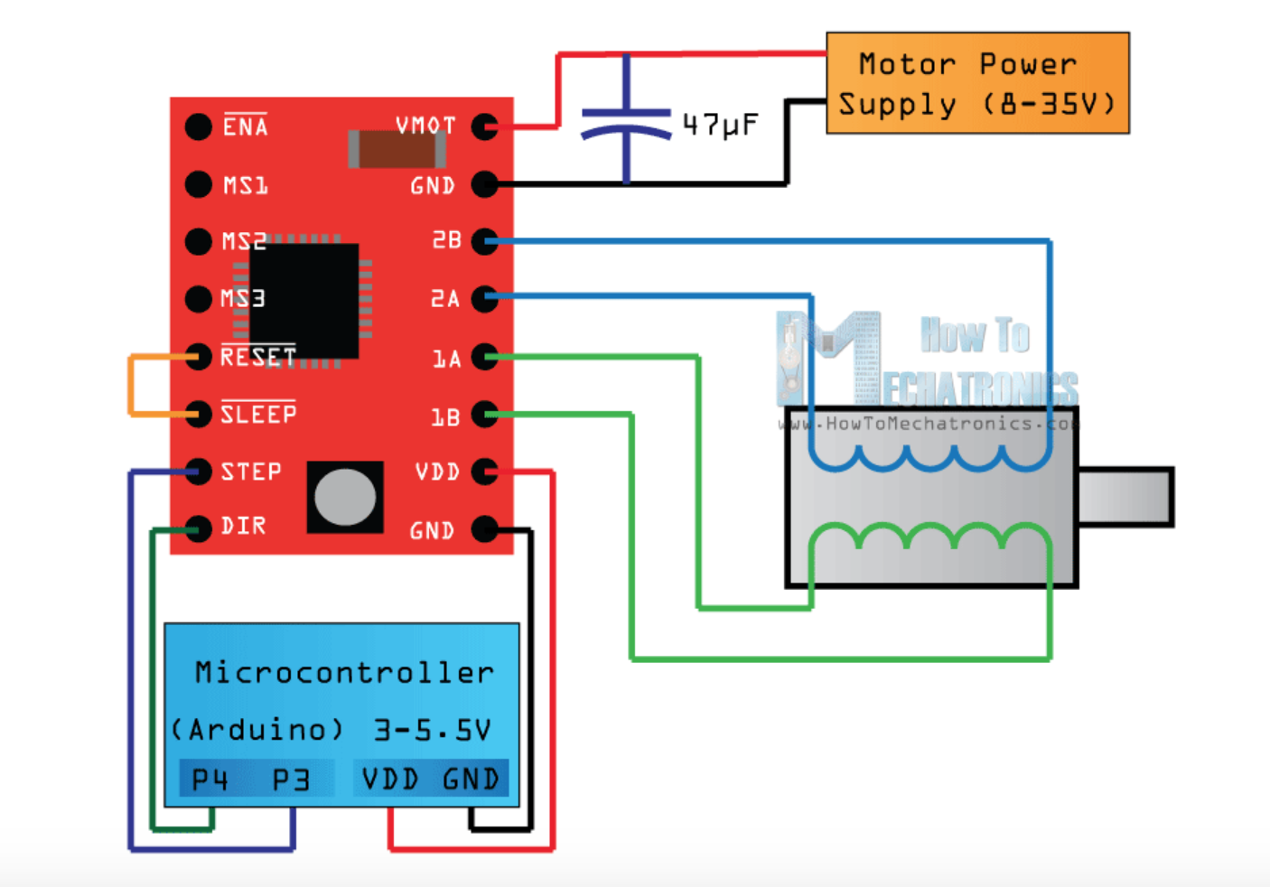
One problem we encountered when attaching the motors was the correct assignment of the cables/pins,
as a wrong correspondence results in wrong or no movement.
In both tutorials helpful pictures were provided.
Use them to identify the correct pins on the board and the cables.
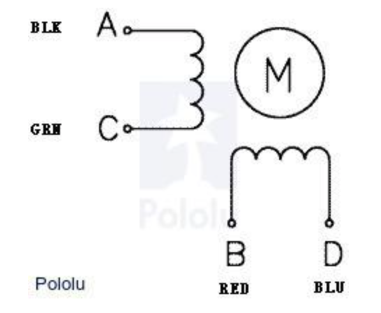
A stepper motor consists of two spools resulting in four cables.
The color of the cables encodes the correspondence to a spool.
The pins on the FabScan shield or the driver are labeled with numbers and letters. The Polulu driver pins have the pins
1A, 1B, 2A, 2B. The number indicates the spool while the letters distinguish the pins for one spool. So each spool has two pins and
spools with the same number need to bee connected when connecting the stepper motor to the Polulu.
The left picture above also shows a colour coding for the stepper motor. This is quite helpful but if the color differs for your
stepper motor you need to find out which two cables of four belong to one spool.
Try and error can also work to find out the right combination of the cables. As when they are not connected correclty they state a weird
sound that seems like the motor wants to move but has not enough power. If this happens try another combination of cables.
Note, that the polarity of a spool is not relevant and also exchanging spools is not critical
(Although, both could reverse the direction of motor).
Conclusion
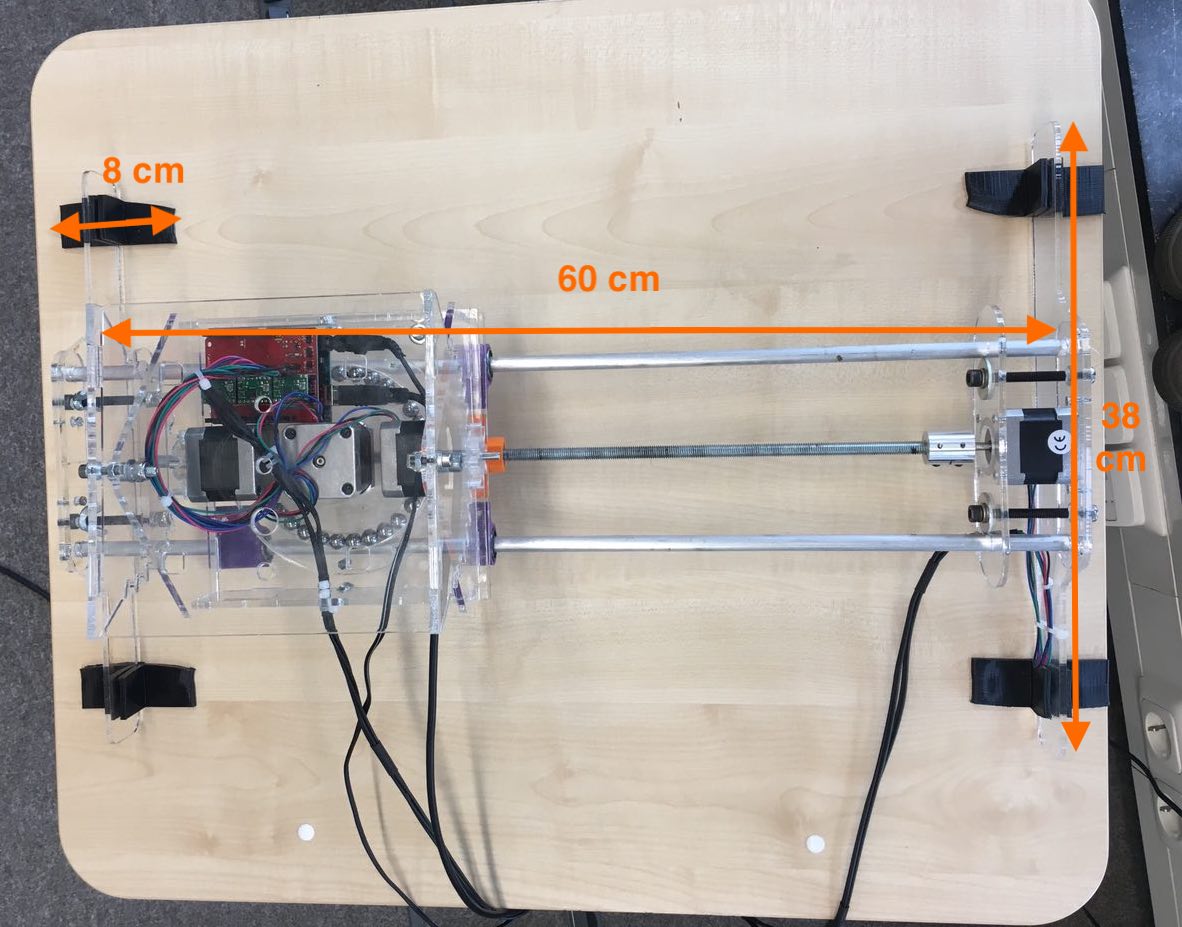
- Threaded rod attached to a stepper motor and 2 aluminum tubes that we use as linear rails. Length 60 cm, width between the aluminum pipe 13 cm.
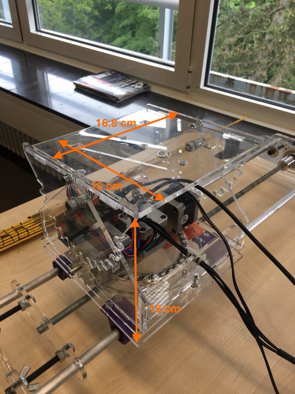
- Camera stand with 3 motors, one rotates the stand around in z-direction and two more tilts the head. Size: 16*16*13 cm
- 3D printed connectors to connect the camera stand to the aluminum tubes and threaded rod.
- The stand of whole construction + 3D printed rubber feet. Length 38 cm, height 13cm.
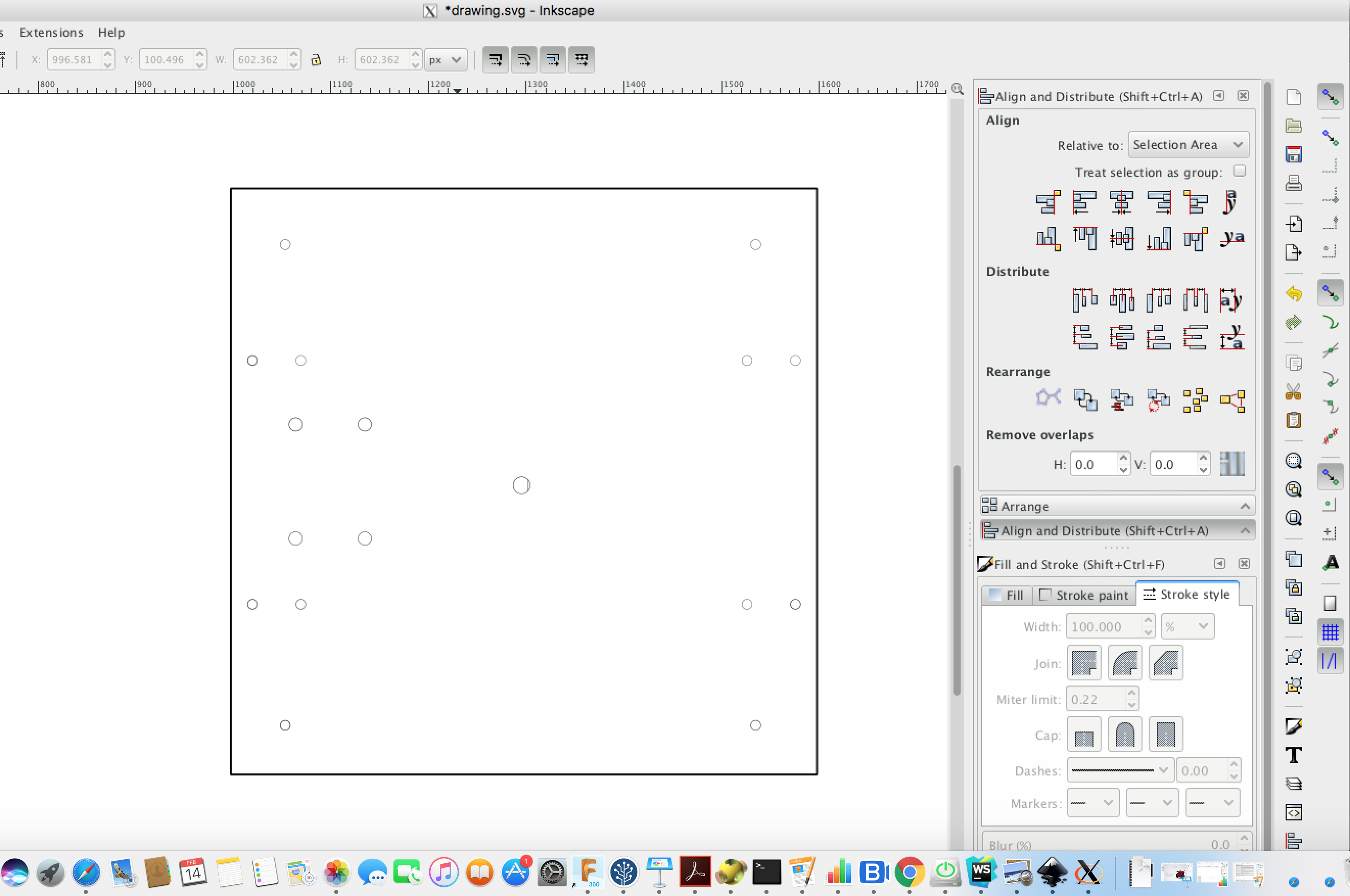
All the sizes can be found on the pictures below:
Programming
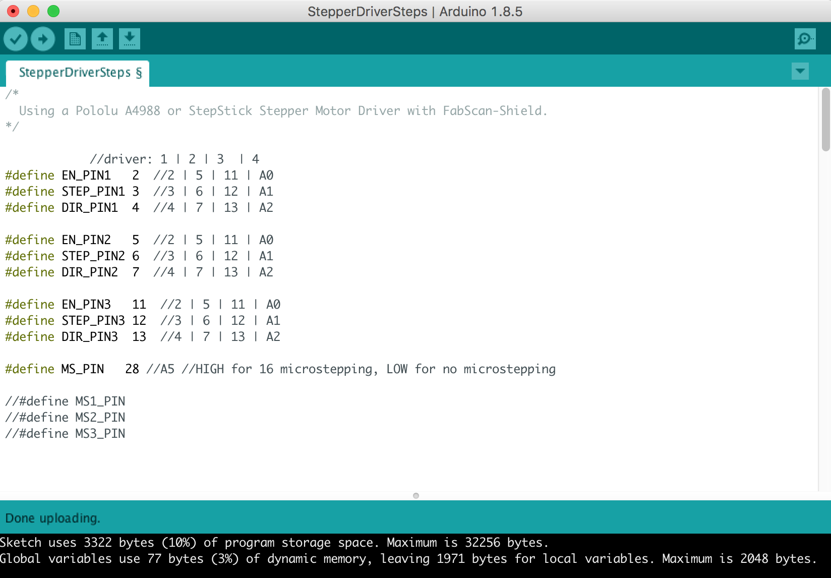
Using the arduino IDE we developed a control software, that is able to control all three axis of the camera
slider.
For this the arduino controls the stepper motor drivers by driving the corresponding digital pins.
The order of motions and deflection is defined in the action method.
Here you can call translate, rotate and tilt to operate the corresponding axis.
Each of these methods takes two parameters distance and delay.
First one controls the number of steps the motor is rotated and second is delay in between each step.
Last one might be adjusted as this appears to influence the torque. We chose a value of 5 milli seconds.
/*
  Using a Pololu A4988 or StepStick Stepper Motor Driver with FabScan-Shield.
*/
//driver: 1 | 2 | 3  | 4
#define EN_PIN1   2  //2 | 5 | 11 | A0
#define STEP_PIN1 3  //3 | 6 | 12 | A1
#define DIR_PIN1  4  //4 | 7 | 13 | A2
#define EN_PIN2   5  //2 | 5 | 11 | A0
#define STEP_PIN2 6  //3 | 6 | 12 | A1
#define DIR_PIN2  7  //4 | 7 | 13 | A2
#define EN_PIN3   11  //2 | 5 | 11 | A0
#define STEP_PIN3 12  //3 | 6 | 12 | A1
#define DIR_PIN3  13  //4 | 7 | 13 | A2
#define MS_PIN   28 //A5 //HIGH for 16 microstepping, LOW for no microstepping

void setup(){
  pinMode(EN_PIN1, OUTPUT);
  digitalWrite(EN_PIN1, HIGH); //deactivate driver (LOW active)
  pinMode(DIR_PIN1, OUTPUT);
  digitalWrite(DIR_PIN1, HIGH); //LOW or HIGH
  pinMode(STEP_PIN1, OUTPUT);
  digitalWrite(STEP_PIN1, LOW);
  digitalWrite(EN_PIN1, LOW); //deactivate driver (LOW active)

  pinMode(EN_PIN2, OUTPUT);
  digitalWrite(EN_PIN2, HIGH); //deactivate driver (LOW active)
  pinMode(DIR_PIN2, OUTPUT);
  digitalWrite(DIR_PIN2, HIGH); //LOW or HIGH
  pinMode(STEP_PIN2, OUTPUT);
  digitalWrite(STEP_PIN2, LOW);
  digitalWrite(EN_PIN2, LOW); //activate driver

  pinMode(EN_PIN3, OUTPUT);
  digitalWrite(EN_PIN3, HIGH); //deactivate driver (LOW active)
  pinMode(DIR_PIN3, OUTPUT);
  digitalWrite(DIR_PIN3, HIGH); //LOW or HIGH
  pinMode(STEP_PIN3, OUTPUT);
  digitalWrite(STEP_PIN3, LOW);
  digitalWrite(EN_PIN3, LOW); //activate driver

  pinMode(MS_PIN, OUTPUT);
  digitalWrite(MS_PIN, HIGH); //microstepping
}

#define STEPS_PER_REVOLUTION 200
#define LENGTH 400
#define PITCH 1.25

#define GEAR_RATIO 4 // 30/8

#define CW LOW
#define CCW HIGH
#define AWAY LOW
#define TOWARDS HIGH
#define UP LOW
#define DOWN HIGH

#define XW 10
#define RW 10
#define TW 10

void action(){

  //transitionUnified(0, -20, 30, 1 , 10);

  translate(0000, 3);

  //tilt(-30, 10);
  //tilt(-30, 10);
  //tilt(60, 20);
  //tilt(-120, 20);
  //tilt(60, 20);
  //rotate(30, 10);

}

void loop(){
  action();
  while(1){}
}

void transitionUnified(int16_t x, int16_t r, int16_t t, uint16_t divisions, uint16_t wait){
  transition(
    (int16_t)((float)x/PITCH*200),
    (int16_t)((float)r*200/360),
    (int16_t)((float)t*200/360*4),
    divisions, wait);
}

void transition(int16_t x, int16_t r, int16_t t, uint16_t divisions, uint16_t wait){
  //moved
  int16_t xm = 0;
  int16_t rm = 0;
  int16_t tm = 0;

  //delta
  float dx = ((float)x) / divisions;
  float dr = ((float)r) / divisions;
  float dt = ((float)t) / divisions;

  for(uint16_t i = 0; i < divisions + 1; i++){
    //target
    int16_t xt = (uint16_t)(dx * i);
    int16_t rt = (uint16_t)(dr * i);
    int16_t tt = (uint16_t)(dt * i);

    //move
    int16_t mx = xt - xm;
    int16_t mr = rt - rm;
    int16_t mt = tt - tm;
    xm += mx;
    rm += mr;
    tm += mt;

    unsigned long pre = millis();
    translate(mx, XW);
    rotate(mr, RW);
    tilt(mt, TW);

    //delay(wait - (millis() - pre));
  }

}

void translate(int16_t s, uint8_t t){
  operate(s > 0 ? AWAY : TOWARDS, s, t, DIR_PIN1, STEP_PIN1);
}

void rotate(int16_t s, uint8_t t){
  operate(s > 0 ? CW : CCW, s, t, DIR_PIN3, STEP_PIN3);
}

void tilt(int16_t s, uint8_t t){
  operate(s > 0 ? UP : DOWN, s, t, DIR_PIN2, STEP_PIN2);
}

void operate(uint8_t d, int16_t s, uint8_t t, uint8_t dir_pin, uint8_t step_pin){
  digitalWrite(dir_pin, d);
  if(s < 0) s = -s;
  for(int16_t i = 0; i < s; i++){
    digitalWrite(step_pin, HIGH);
    delay(t);
    digitalWrite(step_pin, LOW);
    delay(t);
  }
}
Final machine
Future Development Opportunities
- Build a camera slider with a bigger transition axis
- Think about an opportunity how to add transition in the y-axis as well
- How about other material than acrylic? Acrylic is fine with e.g. rain compared to e.g. MDF. But is there a material that is even more robust in terms of heat and conditions outside than acrylic?
All these ideas are worth to think about. Our machine is working in the current status but features to improve the functionality is always worth a try.