This work is licensed
under a
Creative Commons
Attribution-NonCommercial-
ShareAlike 4.0
International License.
Explained how you made your files for machining (2D or 3D).
Show how you made something BIG (describing setting up the machine, using fixings, testing joints, adjusting, depth of cut, etc).
Described problems and how you fixed them.
Included your design files and "hero shot" photos of final object.
In the FabLab Barcelona, we worked mostly with the ShopBot Alpha Milling Machine.
Some machines have a vacuum base that makes it stick to the base.The ones at IAAC need to be held down.
Flutes is the name of the tools that go down. The more different types you know the more you can do.
You cannot go through the width of the material in one go. You need to go down 5 mm and then go around and then go down again.
The maximum distance along the z-axis the tool can cover in one go equals the radius of the tool.
Double sided milling.
SkethChair opensource object.
We will use the 6 mm tool with a flat end since we are not doing a 3D design for now.
Below is a good reference image highlighting different types of joints.

There are different milling strategies. The terms used by the interface are the following:
Engraving: it follows a line from the middle of the line.
Interior Profiling: you cut just along the line. The extra pieces jump.
Pocketing: you create a pocket and therefore the back/bottom will not be removed.
Hole-pocketing: a pocket that is cut-through. The tool also goes through line by the interior of the material.
The profile of our machine is the ShopBot (blue machine) and Max3 for the Precix machine. Those are GCode interpreters.
The top of your object needs to be located at the coordinates 0,0,0.
The long size of the machine is the x-axis and the small is the y-axis.
Once the stock is on the bed, the machine marks where the screens go.
The speed is measured in mm/minute.
The holes for the screws that fix the the stock to the sacrificial board need to be a bit bigger than the diamenter of the tool, in our case, a bit bigger than 6 mm.
You usually go from the small operations to the big ones.
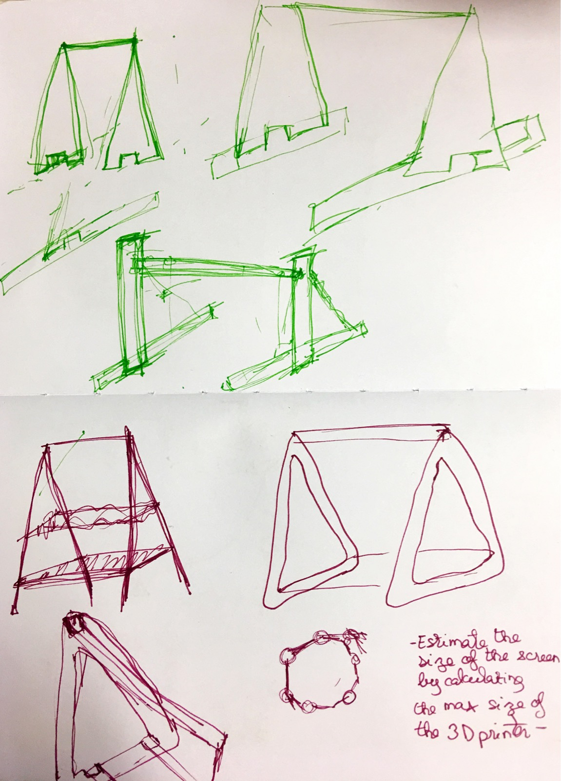
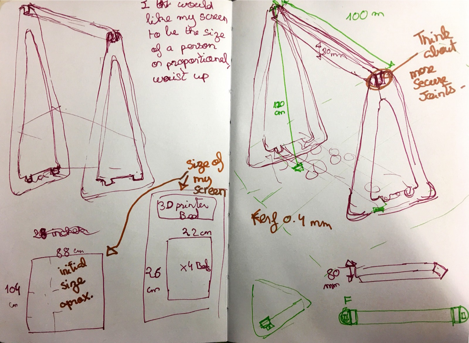
I wanted to take advantage of the infinite possibilities of this week's assignment to create a structure that would hold my interactive screen that I initially wanted to 3D print. I thought in terms of a backdrop tripod, stand, hanging rod, a simple cabinet or even clothes hangers. A couple of references can be found below:

 by AtFab
Below are copies of my brainstorming Sketches.
 Fusion tricks: Combine cut - negative press pull for offset.
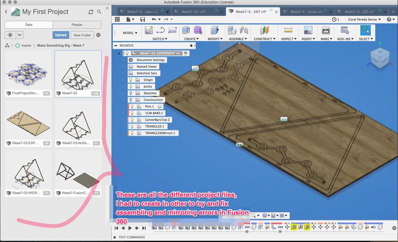
This has possibly been the hardest design assignment for the whole fabacademy. The following tutorials and links were key in helping me solve some of the design issues. Most of them were due to the Fusion 360 learning curve:
How export a DXF of a sheet of metal component in Fusion 360
Below are a couple of shots of the design process:
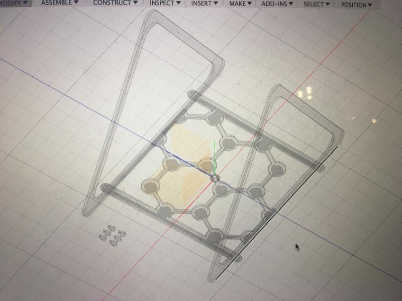
 After a lot of work and great help from Andre Pulcino, I came up with the result below:
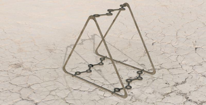 Please consider that when I moved my design to Rhino, some last minute changes had to made so the 3D model above is not 100% accurate. For accurate files please see the Rhino file in the assignment files section.
In the FabLab Barcelona, we made a couple of test cuts to calculate the clearance. I ended up using a clearance of 0.2 mm. See the video below:
Please consider that when I moved my design to Rhino, some last minute changes had to made so the 3D model above is not 100% accurate. For accurate files please see the Rhino file in the assignment files section.
In the FabLab Barcelona, we made a couple of test cuts to calculate the clearance. I ended up using a clearance of 0.2 mm. See the video below:
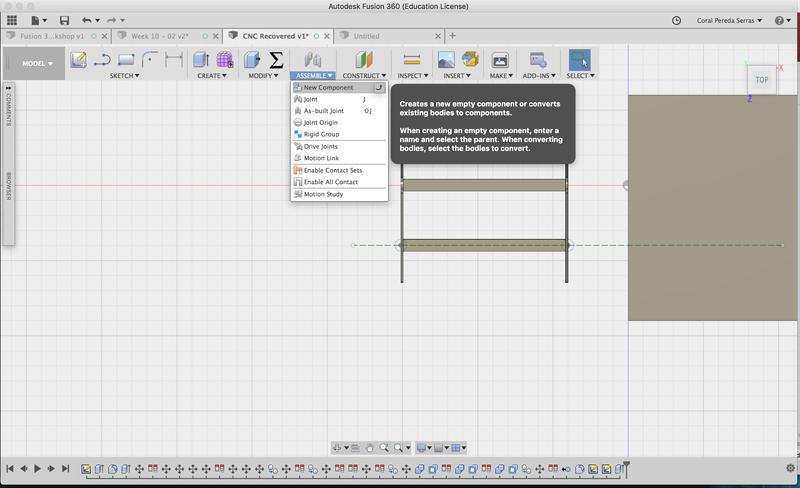
Creating a cutting strategy felt a bit intimidating for me. However, Krisjanis Rijnieks hosted a workshop on using FusionCAM which turned out to be more intuitive than I could have expected. This is probably due to the fact that at this stage I am more familiar with the Fusion 360 interface. Below I give through screenshots a couple pointers of the process. Please note that at the time of the workshop, I did not have the final design finished so I tested out the process with temporary components.
1. In the "Model" workspace in Fusion 360, create new components for each piece:
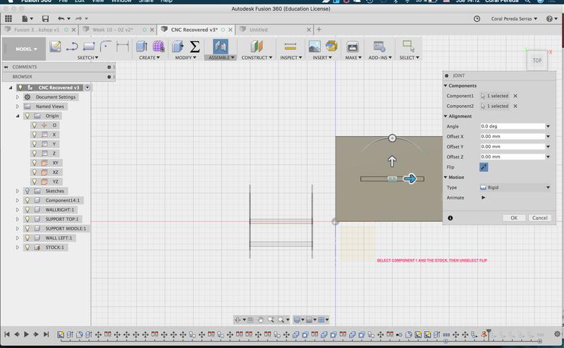
2. Then in the "Assemble" menu, create Joints by selecting each component and the base stock:
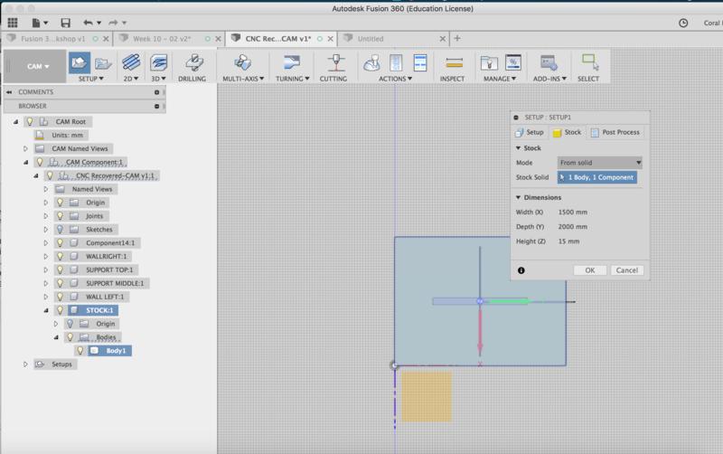
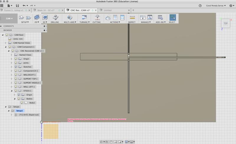
3. Swicth to the "CAM" workspace. In the "Setup" menu, set properties of the stock. In this case, the plywood used is 1500mm wide, 2000mm high and 15 mm deep:
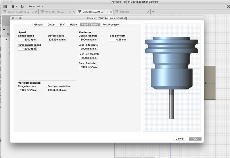
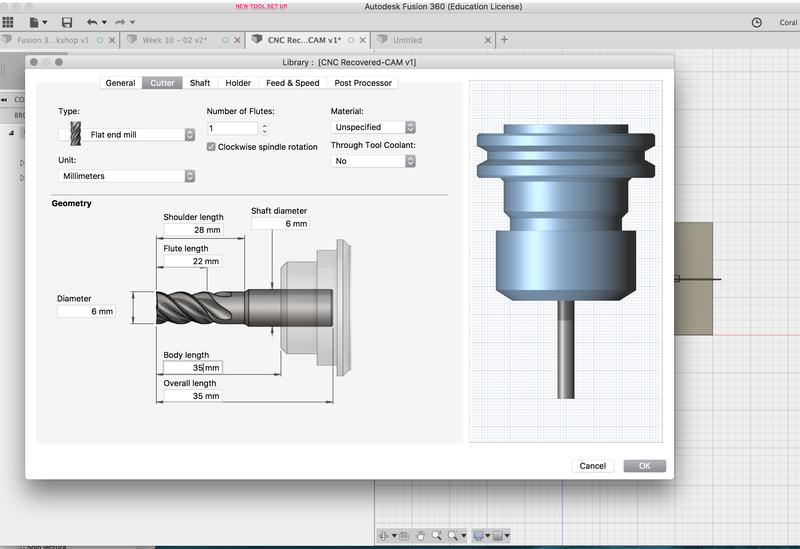
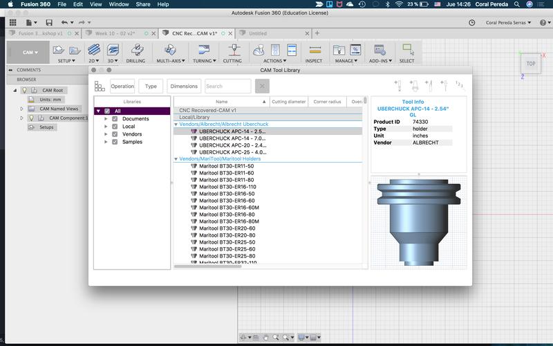
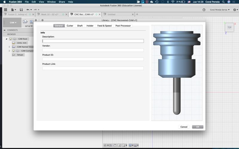
4. In the "Drilling" menu, select go to the tool library.
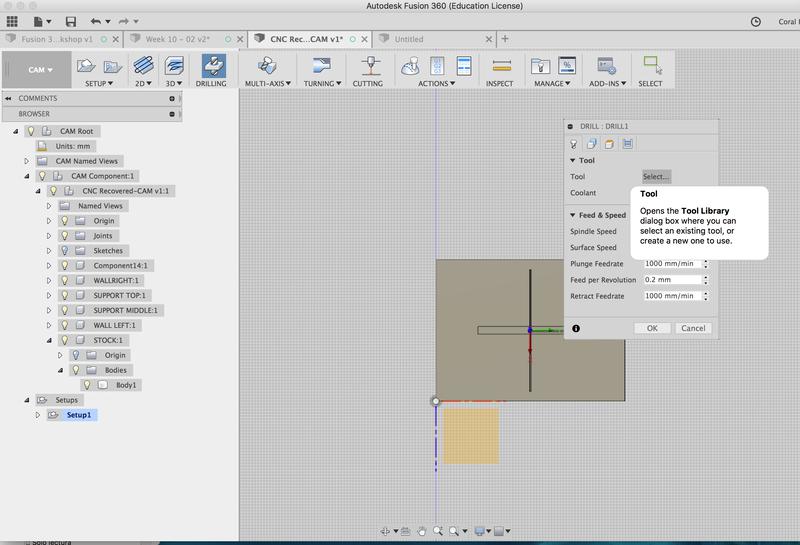
There we must set up a new tool since the one in our lab is not in the library. We used a 6 mm tool.
9. The dogbones in FusionCAM must be placed on an offset projection plane:
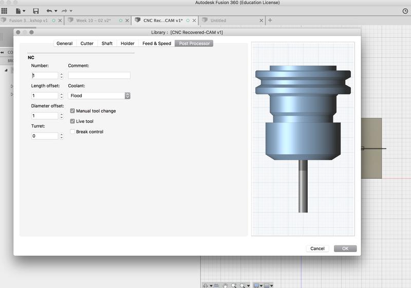
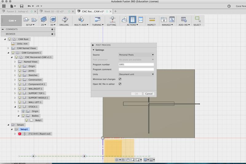
10. Post-process:
Bonus: Great online resource for nesting (fitting all the pieces on the board) http://svgnest.com/
I found this week's concepts very hard to grasp. The shopbot wiki and the guerilla guide made this task a bit easier for me.
I used the following general settings for a flat milling bit with a 6 mm diameter and 1 flute:
RPM: 13000 RPM
Plunge: 1000
Travelling clearance plane: 4000
Max distance travelled by the tool in one step: 4 mm at the very maximum
RhinoCAM comes with the needed settings of some of the most common milling bits, including the 6 mm one I used for my design. However, for some others, the following values must be calculated:
Flute: each of the sharp slots along a milling bit.
Feed Rate: speed at which the machine moves the machining spindle across the part.
Chip Load: size or thickness of the chip that is removed with each flute per revolution.
The formula used to do so is:
For more info, please go to Fablab Speed and Feeds Calculator.
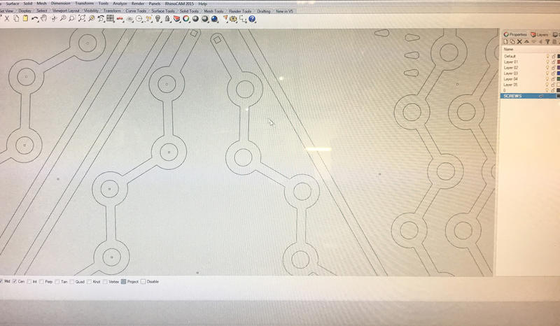
 The gif below summarizes the process of generating the cutting strategy on RhinoCAM.
As you can see, the strategy is divided in eight steps:
1. Screws
2. Dogbones
3. 2 1/2 Axis Pocketing
4. 2 1/2 Axis Profiling
5. 2 1/2 Axis Profiling Inside Circles
6. 2 1/2 Axis Profiling Outside Circles
7. 2 1/2 Axis Profiling Inside Rest
8. 2 1/2 Axis Profiling Outside Rest.
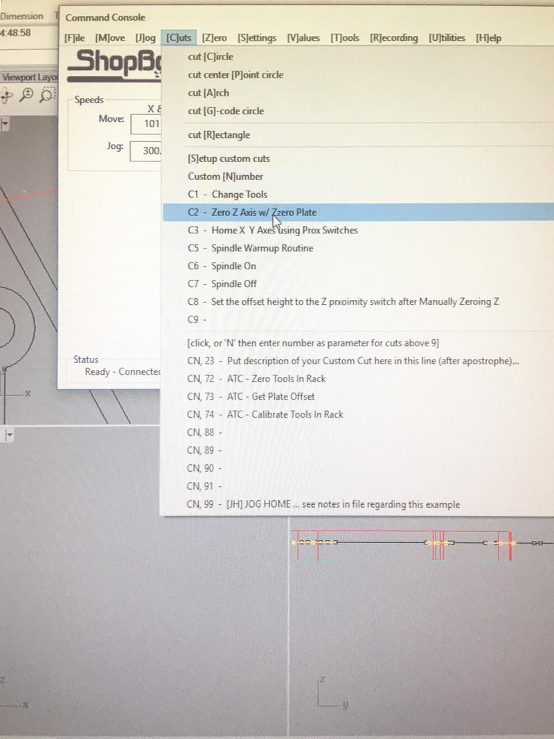
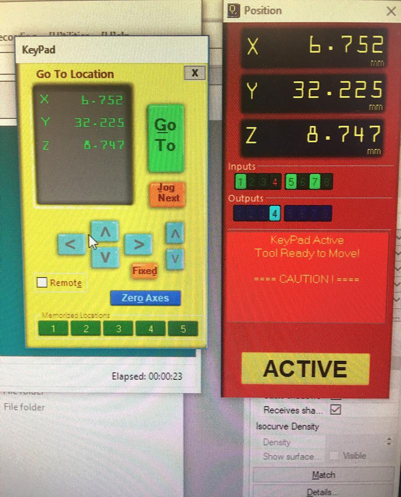
We used the tool below to measure the Z-home coordinate:
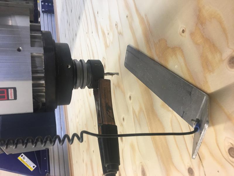
I then took a picture of the home coordinates just in case the power went off. In that case, the machine would have lost the values and we would have to measure it again.
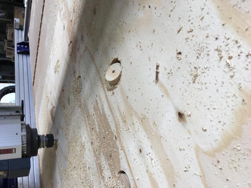
 First, I launched the SCREWS files so that I could drill into screws to secure the board to the sacrificial layer.
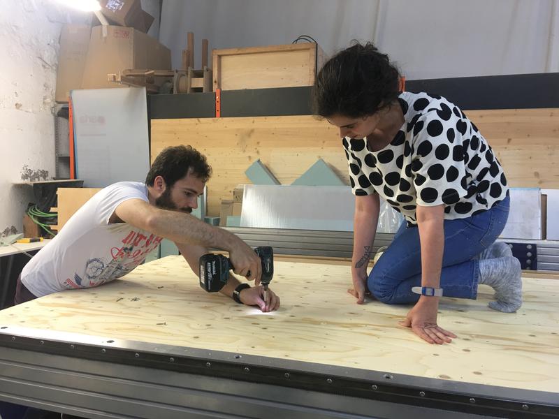
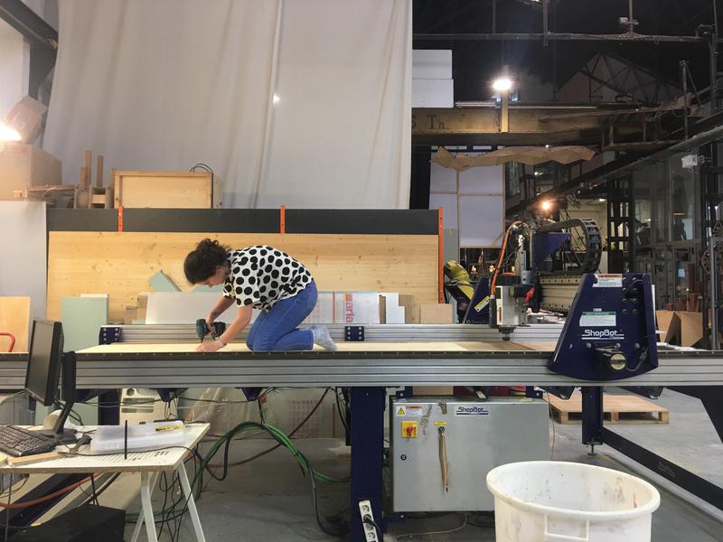 Then I launched the rest of the files and I encountered no major issues in doing so. When it came to the inside of the circles, we were concerned that the dogbones would not be able to hold them in place. When that happens the extra pieces can jump out and hit something. Thankfully, the circles did not jump out but they did tilt. This could be fixed by using longer screws and drilling further down.
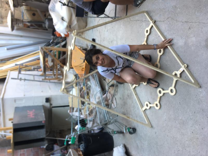
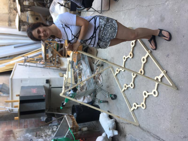
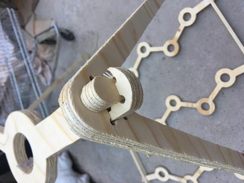
Then I proceed to sand the components of the structure. This was very time consuming. I did not calculate the kerf properly so assembling was a bit of a hassle. I had to sand not only along the depth of the pieces but also along the larger surfaces. At this point it was a matter of trial and error: sanding and testing over and over until the pieces enter the wholes easily and yet stay secured.
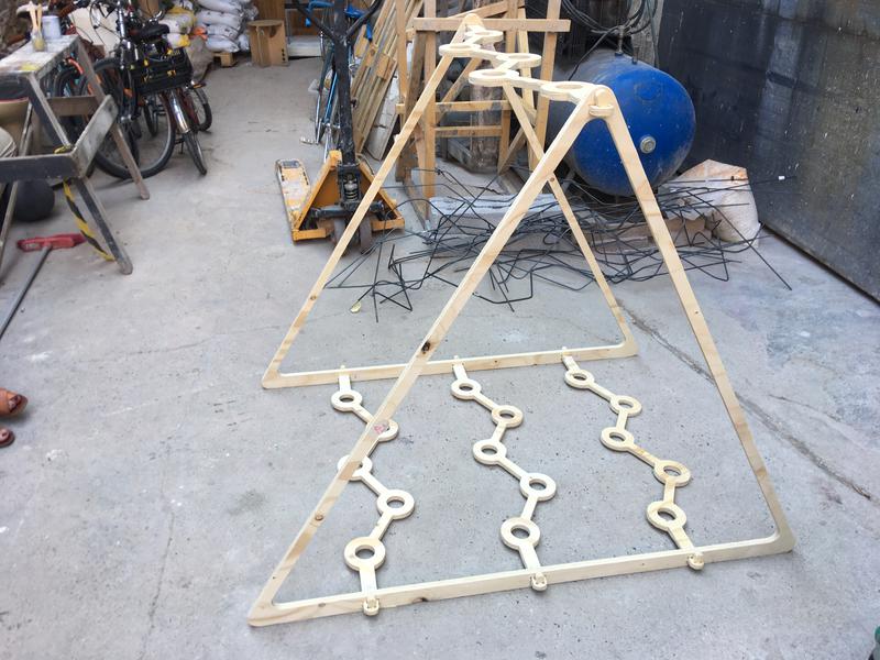
A couple more pictures to get a sense of scale of the structure: